Table of Contents
Advertisement
Advertisement
Table of Contents

Summary of Contents for Hart Scientific 9105
- Page 1 9105 / 9107 Dry-well Calibrator User’s Guide Rev. 2A2801...
- Page 2 © Copyright,1991–2002 Hart Scientific, Inc. 799 E. Utah Valley Drive American Fork, Utah 84003-9775 Telephone: (801) 763-1600 • Fax: (801) 763-1010 Internet: http://www.hartscientific.com E-mail: support@hartscientific.com Rev.2A2801...
-
Page 3: Table Of Contents
Table of Contents 1 Before You Start ......1 Symbols Used ........1 Safety Information. - Page 4 8 Controller Operation......23 8.10 Cut-out ......... . 36 8.11 Controller Configuration .
- Page 5 8.11.5.3 SCO ..........42 9 Digital Communication Interface .
- Page 6 9105 Wiring Diagram ........61...
- Page 7 Tables Table 1 International Electrical Symbols ....... . 1 Table 2 Communications Commands .
-
Page 8: Before You Start
Before You Start Symbols Used Table 1 lists the symbols used on the instrument or in this manual and the meaning of each symbol. Table 1 International Electrical Symbols Symbol 9105/9107 Description AC (Alternating Current) AC-DC Battery Complies with European Union directives... -
Page 9: Safety Information
1 Before You Start Symbol CAT II Safety Information Use the instrument only as specified in this manual. Otherwise, the protection provided by the instrument may be impaired. Refer to the safety information below and throughout the manual. The following definitions apply to the terms “Warning” and “Caution”. •... -
Page 10: Figure 1 Top View
1 Before You Start WARNING: THIS AREA IS HOT Down Exit 9105 Figure 1 Top View 9105/9107... -
Page 11: Cautions
1 Before You Start • DO NOT REMOVE INSERTS AT HIGH TEMPERATURES. Inserts will be the same temperature as the display temperature. Use extreme care when removing hot inserts. • DO NOT operate this unit without a properly grounded, properly polar- ized power cord. -
Page 12: Hart Scientific Authorized Service Centers
Hart product: Hart Scientific, Inc. 799 E. Utah Valley Drive American Fork, UT 84003-9775 Phone: +1.801.763.1600 Telefax: +1.801.763.1010 E-mail: support@hartscientific.com Fluke Nederland B.V. Customer Support Services Science Park Eindhoven 5108 5692 EC Son NETHERLANDS Phone: +31-402-675300 9105/9107... - Page 13 Room 2301 Sciteck Tower 22 Jianguomenwai Dajie Chao Yang District Beijing 100004, PRC CHINA Phone: +86-10-6-512-3436 Telefax: +86-10-6-512-3437 E-mail: xingye.han@fluke.com.cn Fluke South East Asia Pte Ltd. Fluke ASEAN Regional Office Service Center 83 Clemenceau Avenue #15-15/06 Ue Square 239920 SINGAPORE Phone: +65-737-2922 Telefax: +65-737-5155 E-mail: antng@singa.fluke.com...
-
Page 14: Introduction
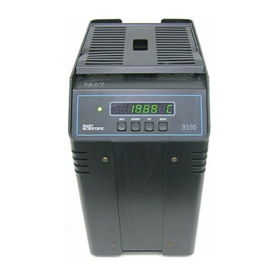
2 Introduction Introduction The Hart Scientific Model 9105/9107 dry-well calibrator may be used as a por- table instrument for calibration of temperature probes. The 9105 operates over the range of –25°C and 140°C. The 9107 operates over the range of –45°C to 140°C. -
Page 15: Specifications And Environmental Conditions
Maintenance and cleaning recommendations can be found in the Maintenance Section of this manual. The instrument operates safely under the following conditions: 9105/9107 3 Specifications and Environmental Conditions 9105 115 VAC (±10%), 50/60 Hz, 230 VAC (±10%), 350 watts 5–50°C (40–120°F) -
Page 16: Warranty
3 Specifications and Environmental Conditions • temperature range 5 - 50°C (41 - 122°F) • ambient relative humidity 15 - 50% • pressure - 75kPa - 106kPa • mains voltage within ± 10% of nominal • vibrations in the calibration environment should be minimized •... -
Page 17: Safety Guidelines
• Use only a grounded AC mains supply of the appropriate voltage to power the instrument. The Model 9105 dry-well requires 3 amps SB at 115 VAC (±10%), 50/60 Hz, 1.6 amps T at 230 VAC (±10%). The Model 9107 dry-well requires 4 amps SB at 115 VAC (±10%), 50/60 Hz, 3.15... - Page 18 4 Safety Guidelines the instrument. Wait until the power has stabilized before re-energizing the instrument. Hart Scientific...
-
Page 19: Quick Start
Unpack the dry-well carefully and inspect it for any damage that may have oc- curred during shipment. If there is shipping damage, notify the carrier immediately. Verify that the following components are present: • 9105 or 9107 Dry-well • 2173 Insert, 1/4” Aluminum • Power Cord • Manual •... -
Page 20: Setting The Temperature
5 Quick Start “POWER” switch. The dry-well will turn on and begin to heat to the previously programmed temperature set-point. The front panel LED display will indicate the actual dry-well temperature. The 9107 is field switchable between 115 V and 230 V. Refer to Section 7.2, Switching to 230 V Operation, for information on switching the voltage. -
Page 21: Parts And Controls
Power Cord - At the rear of the calibrator is the removable power cord that plugs into a standard 115 VAC grounded socket. (230 VAC optional.) Power Switch (9105) - The power switch is located on the rear panel of the calibrator. -
Page 22: Front Panel
The functions of the buttons are as follows: SET – Used to display the next parameter in the menu and to set parameters to the displayed value. DOWN – Used to decrement the displayed value of parameters. Figure 3 Front Panel Down Exit 9105 Hart Scientific... -
Page 23: Constant Temperature Block Assembly
6.3.2 Probe Sleeves and Tongs Probe sleeves of various internal hole sizes are available to allow the user's probe to fit snugly into the well whatever the diameter of the probe. 9105/9107 1/4" Well 1/8" Well 6 Parts and Controls... -
Page 24: Well Insulator (9107Only)
6 Parts and Controls Standard Insert Sizes Model Number 2168 2169 2170 2171 2172 2173 2174 2175 2176 2177 2178 2179 Well Insulator (9107only) The 9107 includes a well insulator made of white polymer foam that fits into the opening above the block (see Figure 5). The well insulator has three purposes: Insulate the top of the block to minimize the vertical temperature gradi- ent in the block. -
Page 25: Figure 5 Well Insulator Top View
6 Parts and Controls insulator flush with the top of the cavity. The well insulator has a slot through which a probe can be inserted. Figure 5 Well Insulator Top View 9105/9107... -
Page 26: General Operation
The power cord may need to be changed to mate with the appropriate 230 VAC or 115 VAC socket. Some options are listed. • 230 VAC: • 115 VAC: 9105/9107 Europe – 10A approved cord with CEE 717 plug US – 15A approved cord with a NEMA 6-15 straight blade plug US –... -
Page 27: Setting The Temperature
Using the same hole for the reference thermometer and the test probe may have better results. This however requires switching the probes which takes more time. -
Page 28: Controller Operation
With manual re- set mode the cut-out must be reset by the operator after the temperature falls below the set-point. 9105/9107 Well temperature in degrees Celsius Indicates cut-out condition 8 Controller Operation... -
Page 29: Figure 6 Controller Function Flowchart
8 Controller Operation Display Temperature EXIT EXIT Reset Cutout Reset Cutout Cutout Active Cutout Active Select Setpoint EXIT Adjust Setpoint EXIT Adjust Units EXIT Scan On/Off EXIT EXIT Scan Rate Display Hold Mode EXIT EXIT Scan Hold EXIT Probe DOWN Menu EXIT Adj. -
Page 30: Temperature Set-Point
“SET”. The number of the set-point memory currently being used is shown at the left on the display followed by the current set-point value. 20.00 C 9105/9107 Access cut-out reset function Cut-out reset function Reset cut-out... -
Page 31: Set-Point Value
8 Controller Operation To change the set-point memory press “UP” or “DOWN”. 3. -10.0 Press “SET” to accept the new selection and access the set-point value. 8.3.2 Set-point Value The set-point value may be adjusted after selecting the set-point memory and pressing “SET”. -
Page 32: Scan Control
This is useful for testing thermal switches and cut-outs. This section ex- plains the functions available for operating the temperature hold feature. An example follows showing how to set up and use the hold feature to test a switch. 9105/9107 Scan function off Scan function on Accept scan setting Scan rate in °C/min... -
Page 33: Hold Temperature Display
8 Controller Operation 8.5.1 Hold Temperature Display When the hold feature is enabled you can easily switch the display between the normal temperature display and the hold temperature display by simply press- ing the “UP” or “DOWN” buttons. The hold temperature display shows the hold temperature on the right and the switch status on the left. -
Page 34: Scan Hold
Suppose you have a thermal switch which is supposed to open at about 75°C and close at about 50°C and you want to test the switch to see how accurate and repeatable it is. You can use the temperature hold feature and the ramp and 9105/9107 Hold mode set to off Automatic mode... - Page 35 8 Controller Operation soak feature (described in detail in the next section) to test the switch. Measure- ments can be made by observing the display or, preferably, by collecting data using a printer or computer connected to the RS-232 port. To set up the test do the following steps.
-
Page 36: Ramp And Soak Program Menu
Number of Program Set-points The first parameter in the program menu is the number of set-points to cycle through. Up to 8 set-points can be used in a ramp and soak program. Pn=8 9105/9107 Time Well temperature Access program menu... -
Page 37: Set-Points
8 Controller Operation Use the “UP” or “DOWN” buttons to change the number from 2 to 8. Pn=3 Press “SET” to continue. Pressing “EXIT” will cause any changes made to the parameter to be ignored. 8.6.2 Set-points The next parameters are the program set-points. 1 25.0 Use the “UP”... -
Page 38: Program Function Mode
Pr=OFF Use the “UP” or “DOWN” buttons to change the status. Pr=StArt Press “SET” to activate the new program control command and return to the temperature display. 9105/9107 Save new setting Action up-stop up-down-stop up-repeat up-down-repeat... -
Page 39: Secondary Menu
8 Controller Operation Secondary Menu Functions which are used less often are accessed within the secondary menu. The secondary menu is accessed by pressing “SET” and “EXIT” simulta- neously and then releasing. The first function in the secondary menu is the heater power display. -
Page 40: Figure 8 Well Temperature Fluctuation At Various Proportional Band Settings
The proportional band adjustment is accessed within the secondary menu. Press “SET” and “EXIT” to enter the secondary menu and show the heater power. Then press “SET” to access the proportional band. Access heater power in secondary menu Heater power in percent -12 Pct Access proportional band 9105/9107... -
Page 41: Cut-Out
8 Controller Operation Pb= 2.01C To change the proportional band press “UP” or “DOWN”. Pb=3.50C To accept the new setting and access the cut-out set-point press “SET”. Pressing “EXIT” will exit the secondary menu ignoring any changes just made to the proportional band value. 8.10 Cut-out As a protection against software or hardware fault or user error, the calibrator is... -
Page 42: Controller Configuration
8.11.1.1 This probe parameter refers to the resistance of the control probe at 0°C. The value of this parameter is set at the factory for best instrument accuracy. 9105/9107 Cut-out set-point New cut-out set-point Accept cut-out set-point... -
Page 43: Alpha
8 Controller Operation 8.11.1.2 ALPHA This probe parameter refers to the average sensitivity of the probe between 0 and 100°C. The value of this parameter is set at the factory for best instrument accuracy. 8.11.1.3 DELTA This parameter relates to the second order nonlinearity of the sensor. The value is set at the factory for best instrument accuracy. -
Page 44: Soak Stability
The BAUD rate of the serial communications may be programmed to 300, 600, 1200, or 2400 BAUD. Use “UP” or “DOWN” to change the BAUD rate value. 2400 b 9105/9107 Cut-out reset mode parameter Cut-out set for automatic reset Cut-out set for manual reset... -
Page 45: Sample Period
8 Controller Operation Press “SET” to set the BAUD rate to the new value or “EXIT” to abort the op- eration and skip to the next parameter in the menu. 8.11.3.2 Sample Period The sample period is the next parameter in the serial interface parameter menu. The sample period is the time period in seconds between temperature measure- ments transmitted from the serial interface. -
Page 46: Ieee-488 Parameters
(Cr), linefeed only (LF), or carriage return and linefeed. Regardless of the option selected the instrument interprets either a carriage re- turn or linefeed as a command termination during reception. 9105/9107 Serial linefeed parameter Current linefeed setting... -
Page 47: Calibration Parameters
8 Controller Operation 8.11.5 Calibration Parameters The user has access to a number of the instrument calibration constants namely CTO, B0, and BG. These values are set at the factory and must not be altered. The correct values are important to the accuracy and proper and safe operation of the calibrator. -
Page 48: Digital Communication Interface
The serial in- terface parameters menu is out- lined in Figure 6. To enter the serial parameter programming mode first press 9105/9107 9 Digital Communication Interface RS-232 Cable Wiring for IBM PC and Compatibles Instrument Connector... -
Page 49: Baud Rate
(“HALF”) or full duplex (“FULL”). With full duplex any commands received by the thermometer via the serial interface are immedi- ately echoed or transmitted back to the device of origin. With half duplex the commands are executed but not echoed. -
Page 50: Serial Operation
Commands may now be sent via the IEEE-488 interface to read or set the tem- perature or access other controller functions. All commands are ASCII charac- ter strings and are terminated with a carriage-return (CR, ASCII 13). Interface commands are listed below. 9105/9107 9 Digital Communication Interface... -
Page 51: Interface Commands
9 Digital Communication Interface Interface Commands The various commands for accessing the calibrator functions via the digital in- terfaces are listed in this section (see Table 2 starting on page 47). These com- mands are used with both the RS-232 serial interface and the IEEE-488 GPIB interface. -
Page 52: Table 2 Communications Commands
Read program control mode Set program control mode: pc=g[o]/s[top]/c[ont] Start program pc=g[o] Stop program pc=s[top] Continue program pc=c[ont] Read program function 9105/9107 Command Example Returned set: 9999.99 {C or F} s=450 scan: {ON or OFF} sc=on sc-of srat: 999.99 {C or F}/min... - Page 53 9 Digital Communication Interface Communications Commands Continued Command Command Description Format Set program function to n pf=n Configuration Menu Probe Menu Read R0 calibration parameter r[0] Set R0 calibration parameter to n r[0]=n Read ALPHA calibration parameter al[pha] Set ALPHA calibration parameter to n al[pha]=n Read DELTA calibration parameter de[lta]...
- Page 54 Note: When DUPLEX is set to FULL and a command is sent to READ, the command is returned followed by a carriage return and linefeed. Then the value is returned as indicated in the RETURNED column. 9105/9107 Command Example Returned...
-
Page 55: Test Probe Calibration
All dry-wells have horizontal and vertical gradients that change with temperature . This is an unknown variable which can be factored out if probes are the same 9105/9107 10 Test Probe Calibration... -
Page 56: Calibration Of Multiple Probes
10 Test Probe Calibration type, length, diameter, and material. Probes should be inserted to the same depth in the well. The following procedure can be used to calibrate a probe against a reference while eliminating error due to temperature gradients between wells. Place the reference probe in one well. -
Page 57: Vertical Gradient
Decreasing the time required for the calibration process can be accomplished by knowing how soon to make the measurement. It is recommended that typi- cal measurements be made at the desired temperatures with the desired test probes to establish these times. 9105/9107 10 Test Probe Calibration... -
Page 58: Calibration Procedure
11.1.1 Calibration Equipment Calibration requires a standard thermometer that is adequately accurate and fits properly into one of the reference holes in the block. Recommended equipment includes a laboratory grade PRT with a length of 230 to 300 mm (9 to 12 inches) and a diameter of 4.76 or 6.35 mm (3/16 or 1/4 inches). - Page 59 Adjust the ALPHA calibration pa- rameter (see Section 8.11.1.2) to make the block temperature as mea- sured with the standard thermometer match the set-point. The approximate ratio between a change in ALPHA and a change in tem- perature at 100°C is about 0.00004 to 1.
-
Page 60: Maintenance
Service to be sure that the proposed method will not damage the equip- ment. • If the instrument is used in a manner not in accordance with the equip- ment design, the operation of the dry-well may be impaired or safety haz- ards may arise. 9105/9107 12 Maintenance... - Page 61 12 Maintenance • The over-temperature cut-out should be checked every 6 months to see that it is working properly. In order to check the user selected cut-out, fol- low the controller directions (Section 8.2) for setting the cut-out. Both the manual and the auto reset option of the cut-out should be checked.
-
Page 62: Troubleshooting
If the display flashes “ or “ If the display flashes “ 9105/9107 Causes and Solutions Power the unit on and watch the display. If the first number displayed is less than “ re-programmed for R0, ALPHA, and DELTA. These numbers can be found on the Report of Calibration that was shipped with the unit. -
Page 63: Comments
13 Troubleshooting Problem Temperature readout is not the actual temperature of the well 13.2 Comments 13.2.1 EMC Directive Hart Scientific’s equipment has been tested to meet the European Electromag- netic Compatibility Directive (EMC Directive, 89/336/EEC). Selection of Light Industrial of Heavy Industrial compliance has been based on the intended use of the instrument. -
Page 64: Wiring Diagrams
13 Troubleshooting 13.3 Wiring Diagrams Figure 10 9105 Wiring Diagram 9105/9107... -
Page 65: Figure 11 9107 Wiring Diagram
13 Troubleshooting Figure 11 9107 Wiring Diagram Hart Scientific...
Need help?
Do you have a question about the 9105 and is the answer not in the manual?
Questions and answers