Advertisement
Quick Links
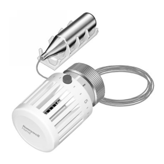
The T104F Thermostatic Control is used with a V110
Valve Body to control radiators, convectors, baseboard
heating units, or other heating units with standard capacity
requirements. The control is self-powered and requires no
electrical connection. The T100A includes a setpoint dial
and valve actuator, connected by a capillary tube to a sensor.
The T104F Control attaches to the valve body by threaded
connections and may be mounted at any angle. Install the
remote sensor beneath the heating coils in the cold air re-
turn, or on a nearby wall where the air flow is not restricted.
The setpoint dial has reference marks (1-6). The control
has a low limit of 43°F (6°C) when the dial is turned fully
clockwise to the frost protection mark*. The red button
indicates the 68°F (20°C) setpoint limit. Higher settings may
be made by holding in the button while turning. The thermo-
static sensor is protected by a safety spring against tempera-
tures to 125°F (52°C).
MATERIALS OF CONSTRUCTION:
Body: Industrial grade plastics with low thermal
conductivity.
Fastening Ring: Plated brass.
Internal Parts: Brass thermostat capsule, other metals.
TEMPERATURE RANGE: 43° to 79°F (6° to 26 °C).
MAX. SENSOR TEMPERATURE: 125°F (52°C).
MAX. OVERALL DIMENSIONS: 2-1/8 in. (54 mm) wide,
3-5/16 in. (84 mm) long. See Fig. 1.
CAPILLARY LENGTH: 6 ft. 8 in. (2 m).
TEMPERATURE SETTINGS:
These are the setpoint temperatures, which correspond
to the setpoint dial reference marks, under ideal conditions.
Factors affecting the temperature at the sensor vary for each
installation. It may be necessary to adjust the setpoint
higher or lower to obtain the desired space temperature.
Temperature
0
°F
Off 43 46 54 61 68 73 79
°C
Off
Specifications
*
1
2
3
4
5
6
8
12 16 20 23 26
Thermostatic Control
Fig. 1—T104F dimensions in in. (mm).
M9731
6
AVAILABLE VALVE BODIES:
See Fig. 2.
C. H. • 12-94 • ©Honeywell Inc. 1994 • Form Number 62-3047
1
T104F
M9730
2 1/8 (54)
3 5/16
(84)
MAX.
62-3047
Advertisement

Related Manuals for Honeywell Braukmann T104F


Summary of Contents for Honeywell Braukmann T104F
- Page 1 Temperature °F Off 43 46 54 61 68 73 79 AVAILABLE VALVE BODIES: °C 12 16 20 23 26 See Fig. 2. C. H. • 12-94 • ©Honeywell Inc. 1994 • Form Number 62-3047 62-3047...
-
Page 2: Installation
When mounting the T104F, make sure the bosses on sure if the sensor is located a minimum of 3 in. (76 mm) the T104F base fit securely into the valve body grooves. beneath the heating coils in the cold air return. Coil Firmly hand tighten the knurled ring. -
Page 3: Settings And Calibration
Setting the Limit To set a limit different from the factory setting, proceed as follows: The T104F Control includes an adjustable range limit- 1. Determine the desired temperature range limit or lock- ing pin (order additional pins separately). The pin is fac- ing temperature. - Page 4 For the 72°F (22°C) single temperature according to the instructions in Recalibrate T104F Control setting, align the red button with the center of the adjustable section.
-
Page 5: Troubleshooting
Troubleshooting Sympton Possible Cause Solution All sections of 1. Many radiators are over-sized and all 1. System is operating properly. the radiator are sections are not required to heat up to not heating. maintain the set room temperature. Underheating. 1. Sensor is in the wrong location. 1. - Page 6 Honeywell Braukmann Honeywell Braukmann Helping You Control Your World Honeywell Inc. Honeywell Limited—Honeywell Limitée 1985 Douglas Drive North 740 Ellesmere Road Golden Valley, MN 55422 Scarborough, Ontario M1P 2V9 QUALITY IS KEY 62-3047 Printed in Germany www.honeywell.ca/braukmann...