Table of Contents
Advertisement
Advertisement
Table of Contents

Summary of Contents for System Fidelity DVD-R150
-
Page 2: Table Of Contents
CONTENTS SAFETY INFORMATION IMPORTANT SAFETY INSTRUCTIONS REMOTE CONTROLLER FRONT PANEL INFORMATION REAR PANEL INFORMATION REMOTE CONTROLLER INFORMATION CONNECTION LOUDSPEAKER CONNECTIONS AUDIO CONNECTIONS DIGITAL CONNECTIONS VIDEO CONNECTIONS FRONT INPUT CONNECTIONS AERIAL CONNECTIONS FUNCTION AND OPERATION EXPLANATION RDS DATA SYSTEM REGION MANAGEMENT INFORMATION TROUBLESHOOTING GUIDE SPECIFICATIONS... -
Page 3: Safety Information
SAFETY INFORMATION Caution: To reduce the risk of electric shock, do not remove Cover (or back) No user-serviceable parts inside. Refer servicing to qualified service personnel. This lightning flash with arrowhead symbol, within an equilateral triangle is intended to alert the user to the presence of uninstalled “dangerous voltage”... -
Page 4: Important Safety Instructions
IMPORTANT SAFETY INSTRUCTIONS CAUTION: READ THIS BEFORE OPERATING YOUR UNIT. READ AND FOLLOW INSTRUCTIONS: All the safety and operation instructions should be read before the product is operated. Follow all operation instructions within this manual. RETAIN INSTRUCTIONS: The safety and operation instructions should be retained for future reference. HEED WARNINGS: Comply with all warnings on the product and in the operation instructions. - Page 5 IMPORTANT SAFETY INSTRUCTIONS 15. REPLACEMENT PARTS: Should replacement parts be required, have the service technician verify that the replacement parts he uses have the same safety characteristics as the original parts. Use of unauthorized replacements parts can cause fire or electric shock. 16.
-
Page 6: Remote Controller
REMOTE CONTROLLER By using the provided remote control unit, the receiver can be BATTERY INSTALLATION controlled from your listening position. To use the remote control unit, point it at the REMOTE SENSOR window of the receiver. Notes: - Even if the remote control unit is operated within the effective range, remote control operation may be impossible if there are any obstacles between the unit and the remote control. -
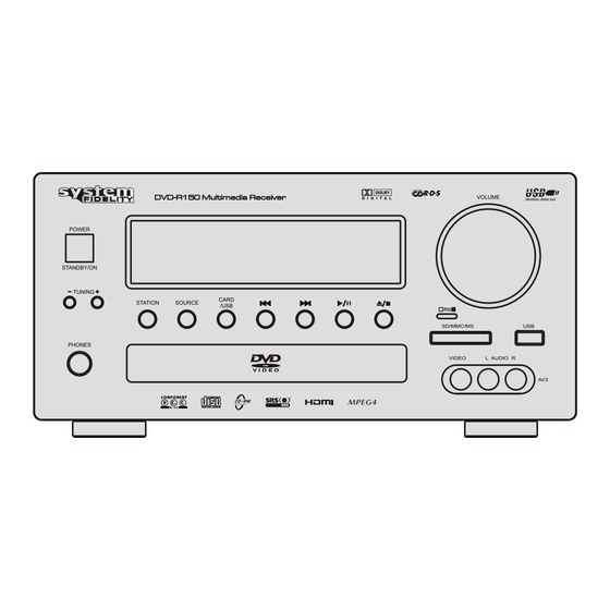
Page 7: Front Panel Information
FRONT PANEL INFORMATION VOLUME UNIVERSAL SERIAL BUS POWER STANDBY/ON TUNING CARD STATION SOURCE /USB PHONES 1. Power Standby/On When this unit is powered on, press this button to turn the unit into standby mode, press it again to turn on the unit. 2. -
Page 8: Rear Panel Information
REAR PANEL INFORMATION Dolby and the double-D symbol are registered trademarks of Dolby Laboratories. SRS and (o) symbol are trademarks of SRS Labs, Inc. 1. Power On/Off Switches the unit on and off. 2. Mains power lead Once you have completed all connections, plug the AC power lead into an appropriate mains socket. -
Page 9: Remote Controller Information
SLOW/STEP ANGLE GOTO P.SCAN ZOOM MUTE DVD-R150 1. Power key 11. AUX When this button is pressed during the remote standby state, Press this button to select the source of AUX. the power of the unit can be switched on/off. - Page 10 21. Return Under DVD mode, press this button if you want to stop the Press it to cancel the utilizing of controlled menu picture. disc playing. 22. Setup 31. ► You can access the DVD player configuration settings by using the Setup Menu. Press this button if you want to start the disc.
-
Page 11: Connection
CONNECTION LOUDSPEAKER CONNECTIONS Caution: To avoid damaging the speakers with a sudden high-level signal, be sure to switch the power off before connecting the speakers. Check the impedance of your speakers. Connect speaker with an impedance of 8 ohms or more. The amplifier’s red speaker terminals are the + (positive) terminals and the black terminals are the –... -
Page 12: Audio Connections
CONNECTION AUDIO CONNECTIONS Note: Do not plug in the mains power lead or turn on the unit all connections have been made. Connect to source equipment using phono cables (stereo 2RCA-2RCA). Dolby and the double-D symbol are registered trademarks of Dolby Laboratories. SRS and (o) symbol are trademarks of SRS Labs, Inc. -
Page 13: Video Connections
CONNECTION VIDEO CONNECTIONS There are four types of video connections can be made on this unit: Composite, S-Video, SCART and Component. For best picture quality we recommend making Component/SCART video connections, then in declining order of quality, S-Videos and then Composite video connections. TV/MONITOR TV/MONITOR TV/MONITOR... -
Page 14: Aerial Connections
COMMECTIONS AERIAL CONNECTIONS FM aerial Connect an aerial to the FM 75 ohm socket (a simple wire aerial is supplied for temporary use). Extend the lead and move the aerial around until you get the best reception. For continued use, we strongly recommended using a 75 ohm outdoor FM aerial. AM loop aerial Connect each end of the single length antenna to the antenna terminals. -
Page 15: Function And Operation Explanation
FUNCTION AND OPERATION EXPLANATION Turn ON/OFF the unit 5. ZOOM: Enlarge the picture. (CD not valid) 1. Connect the power cord to the rated AC socket. Press the A. Press this key repeatedly to enlarge 1.5 x , 2 x, 3 x, times. POWER ON/OFF switch (on the rear panel), the unit has B. - Page 16 FUNCTION AND OPERATION EXPLANATION General Setup Preferences Page TV Display Normal/PS Normal /LB Audio English Wide French TV Type German Multi Spanish NTSC Italian Video Out Hungarian Slovene Angle Mark Subtitle English French OSD Lang English German French Spanish German Italian Spanish Hungarian...
- Page 17 1). General Setup ● HDMI Audio ● TV Display To select the audio output format from HDMI: SPDIF or PCM. To select the screen format to fit your TV screen. 2). Audio Setup NORMAL/PS (4:3 Pan Scan): To select this screen when this ●...
- Page 18 RADIO OPERATION a. Press Source to select broadcast FM or AM. 1. Select FM or AM broadcasting mode by pressing Source b. Press Tuning- or Tuning+ until the displaying frequency button. begins to change, then release. When this system tunes to 2.
-
Page 19: Rds Data System
RADIO DATA SYSTEM RADIO DATA SYSTEM (RDS) RDS is a method for the transmission of additional information from local Radio Stations. It can only operated in FM mode. For example, name of the station broadcasting, name of the program or the type of program will be shown on the multi-function display. -
Page 20: Region Management Information
REGION MANAGEMENT INFORMATION DVD/VCD/CD player is designed and manufactured to respond to the Region Management Information that is recorded on a DVD disc. If the region number that described on the DVD disc does not correspond to the region number of this player, then the player cannot play the disc. -
Page 21: Specifications
SPECIFICATIONS Audio Section Rated Power Output: FRONT 40 W + 40 W 8 ohm FRONT 50 W + 50 W 4 ohm Total Harmonic Distortion: Less than 0.2% rated power output Line Input (Each Line Input - FRONT SPEAKER OUT) Input Sensitivity/Impedance: 200 mV /47kohm Frequency Response:...
Need help?
Do you have a question about the DVD-R150 and is the answer not in the manual?
Questions and answers