Table of Contents
Advertisement
Quick Links
DESCRIPTION, OPERATION, INSTALLATION AND
MAINTENANCE MANUAL
ME406 ELT
570-1600 Rev. G
Proprietary Information
This document discloses subject matter in which Artex Aircraft Supplies, Inc. has proprietary
rights. Neither receipt nor possession thereof confers or transfers any right to reproduce or
disclose the document, any part thereof, any information therein, or any physical article or
device, or practice any method or process except by written permission from or written
agreement with Artex Aircraft Supplies, Inc.
Advertisement
Table of Contents
Troubleshooting

Related Manuals for ARTEX AIRCRAFT SUPPLIES ME406 ELT

Summary of Contents for ARTEX AIRCRAFT SUPPLIES ME406 ELT
- Page 1 570-1600 Rev. G Proprietary Information This document discloses subject matter in which Artex Aircraft Supplies, Inc. has proprietary rights. Neither receipt nor possession thereof confers or transfers any right to reproduce or disclose the document, any part thereof, any information therein, or any physical article or device, or practice any method or process except by written permission from or written agreement with Artex Aircraft Supplies, Inc.
-
Page 3: Revision History
ARTEX AIRCRAFT SUPPLIES, INC. 570-1600 Revision History REVISION CHANGE DATE RELEASE 06-30-05 DCN 2670 11-17-05 DCN 2777 05-01-06 DCN 2847 08-21-06 DCN 3007 05-21-07 DCN 3076 09-27-07 DCN 3182 03-03-08 DCN 3227 05-19-08 DCN 3413 03-30-09... -
Page 4: Table Of Contents
ARTEX AIRCRAFT SUPPLIES, INC. 570-1600 Table of Content Introduction, Description and Operation .............. 1 Basic Information ....................1 Application ......................1 Description......................2 Certification......................2 Programming ......................3 Operation....................... 4 Accuracy ......................5 1.6.1 Switch Operation ....................5 1.6.2 Self-Test mode ....................5 1.6.3... - Page 5 ARTEX AIRCRAFT SUPPLIES, INC. 570-1600 Registration ......................30 FAA Form 337 ...................... 30 Radio Station License - USA .................. 30 U.S.A.A Registration ..................... 31 Canadian Registration ................... 33 Other Country Registration..................33 Maintenance ......................34 Periodic Maintenance for the United States ............34 Canadian Maintenance Requirements..............
- Page 6 ARTEX AIRCRAFT SUPPLIES, INC. 570-1600 Software ......................49 Weights ....................... 49 6.10 Table 4 – Weights....................49 Electrical Loading of Aircraft System ..............50 6.11 Table 5 - Electrical Loading of Aircraft System ............50 ME406 Series DO-160D Environmental Qualification Form........58 6.12...
- Page 7 ARTEX AIRCRAFT SUPPLIES, INC. 570-1600 Table of Figures Figure 1 – ME406 Installed View ................... 4 Figure 2 – ELT Front View..................... 6 Figure 3 – Mounting Hole Diagram for Artex 110 Series and Narco ELT ........ 11 Figure 4 – Mounting Hole Diagram for Artex 200 Series ............12 Figure 5 –...
-
Page 9: Introduction, Description And Operation
ARTEX AIRCRAFT SUPPLIES, INC. 570-1600 Introduction, Description and Operation Basic Information This manual describes the operation, installation and maintenance of the Artex models ME406 and ME406HM emergency locator transmitters (ELTs). The information is provided to ensure initial and continued airworthiness. Information presented in this manual is accurate at time of printing, but is subject to change. -
Page 10: Description
ARTEX AIRCRAFT SUPPLIES, INC. 570-1600 Description The ME406 and the ME406HM are type AF (automatic fixed) beacons. The ME406HM also features an additional 5 axis G-switch module that allows the ELT to be activated in any of six axes. These 5 auxiliary “G” switches are a “non-TSO function” as described in FAA Notice 8150.3. -
Page 11: Programming
ARTEX AIRCRAFT SUPPLIES, INC. 570-1600 • COSPAS-SARSAT T.001 and T.007 • 47 CFR Part 87 (FCC requirements) Note: Per FCC regulations 47 CFR § 2.902, the ELT is tested per “Verification” method, the FCC does not issue certificates for ELTs. The FCC identifier grantee code for Artex is H4K. -
Page 12: Operation
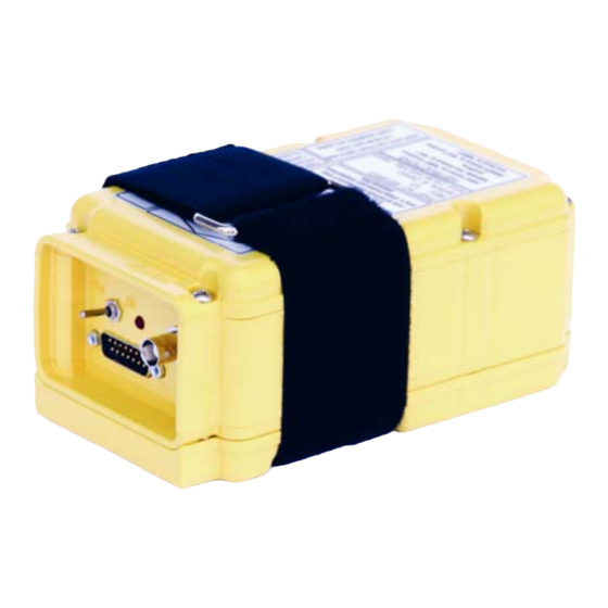
ARTEX AIRCRAFT SUPPLIES, INC. 570-1600 Figure 1 – ME406 Installed View Operation In the event of a crash, the ME406 or ME406HM activates automatically (automatic fixed “AF” configuration), and transmits the standard swept tone on 121.5 MHz lasting until battery power is gone. -
Page 13: Accuracy
ARTEX AIRCRAFT SUPPLIES, INC. 570-1600 In addition, for the first 24 hours of operation, a 406 MHz signal is transmitting at 50-second intervals. This transmission lasts 440 ms and contains identification data programmed into the beacon and is received by COSPAS-SARSAT satellites. The transmitted data is referenced in a database (maintained by the national authority responsible for ELT registration) and used to identify the beacon and owner. -
Page 14: Figure 2 - Elt Front View
ARTEX AIRCRAFT SUPPLIES, INC. 570-1600 NOTE: Any time the ELT is activated, it is transmitting a 121.5 MHz distress signal. Therefore, all activations of the ELT should be kept to a minimum. Local or national regulations may limit testing of the ELT or impose special requirements or conditions to perform testing. -
Page 15: Installation For The United States
ARTEX AIRCRAFT SUPPLIES, INC. 570-1600 Installation for the United States Introduction to Installation Installations must be made by qualified personnel in accordance with FAA regulations. Duplicating a previous installation may not be acceptable. Refer to the following: • FAA – Advisory Circular (AC) 43.13 (Acceptable Methods, Techniques, and Practices –... -
Page 16: Parts List
ARTEX AIRCRAFT SUPPLIES, INC. 570-1600 Parts List Installation kits offered for the ME406 include the necessary ELT-related components. The table below lists typical options. Parts can be ordered separately. Additional parts may also be available. Contact Artex at 1-800-547-8901 for details, pricing and availability. -
Page 17: Mount Elt
ARTEX AIRCRAFT SUPPLIES, INC. 570-1600 Additional items required. In addition to the kit, the following are examples of parts and tools that may be required, but are not provided: • Miscellaneous tools: Drill, Phillips screwdriver (#2 bit), center punch, wire stripper, wrenches for aircraft disassembly/assembly •... - Page 18 ARTEX AIRCRAFT SUPPLIES, INC. 570-1600 The mounting location must conform to the requirements of RTCA DO-204 and AC 43.13. DO- 204 Sec 3.1.8 states: “The ELT shall be mounted to primary aircraft load carrying structures such as trusses, bulkheads longerons, spars, o floor beams (not aircraf skin). The mounts shall have a maximum static local deflection no greater than 2.5 mm...
-
Page 19: Figure 3 - Mounting Hole Diagram For Artex 110 Series And Narco Elt
ARTEX AIRCRAFT SUPPLIES, INC. 570-1600 Figure 3 – Mounting Hole Diagram for Artex 110 Series and Narco ELT NOTE: DRAWING IS NOT TO SCALE. DO NOT USE AS A TEMPLATE FOR DRILLING HOLES. Metric Dimensions 50.8mm X 139.5mm Page 11 of 60... -
Page 20: Figure 4 - Mounting Hole Diagram For Artex 200 Series
ARTEX AIRCRAFT SUPPLIES, INC. 570-1600 Figure 4 – Mounting Hole Diagram for Artex 200 Series NOTE: DRAWING IS NOT IS SCALE – DO NOT USE AS A TEMPLATE FOR DRILLING HOLES Metric Dimensions 46.4mm X 74.8mm Page 12 of 60... -
Page 21: Figure 5 - Mounting Hole Diagram For Pointer
ARTEX AIRCRAFT SUPPLIES, INC. 570-1600 Figure 5 – Mounting Hole Diagram for Pointer NOTE: DRAWING IS NOT TO SCALE – DO NOT USE AS A TEMPLATE FOR DRILLING HOLES Metric Dimensions 64.7mm X 108.2mm Page 13 of 60... -
Page 22: Mount Antenna
ARTEX AIRCRAFT SUPPLIES, INC. 570-1600 Mount Antenna The ELT antenna must be mounted in accordance with the requirements of RTCA/DO-204, Section 3.1.10 and RTCA/DO-183 Section 3.1.10. Locate the antenna at least 30 inches (75 cm) away from other antennas, wires, vertical stabilizer, etc. to minimize distortion of the radiated field and interference with other equipment. -
Page 23: Whip' Antenna - P/N 110-773
ARTEX AIRCRAFT SUPPLIES, INC. 570-1600 ‘Whip’ Antenna – P/N 110-773 2.4.1 See Figure 21. Refer to AC 43.13 for guidance. It is the responsibility of the installer to determine the appropriate and adequate antenna installation. To ensure adequate support for associated air loading during flight, use of a backing plate or doubler (not supplied) may be required. -
Page 24: Rod Antenna - P/N 110-338
ARTEX AIRCRAFT SUPPLIES, INC. 570-1600 Apply a small, smooth fillet with RTV sealant around the periphery of the antenna base to seal out moisture. For maximum signal strength, the length of the antenna coax to the ELT should be as short as possible (use of the standard 6-foot (1.8 M) coax is recommended when... -
Page 25: Composite Aircraft Installation
ARTEX AIRCRAFT SUPPLIES, INC. 570-1600 Mount the antenna using four 100º countersink #8-32 (M5) stainless steel machine screws and associated hardware. Tighten to 20 inch-lbs (226 Newton-cm) max. Apply a small, smooth fillet with RTV sealant around the periphery of the antenna base to seal out moisture. -
Page 26: Mount Audio Indicator ("Buzzer")
ARTEX AIRCRAFT SUPPLIES, INC. 570-1600 Mount Audio Indicator (“buzzer”) An audio indicator is required for TSO-C126 approval. The indicator, i.e., “buzzer” (P/N 452- 6505) is powered by the ELT and, therefore independent of the aircraft power system. When the ELT is activated, the buzzer ‘beeps’ periodically. The time between pulses lengthen after a predetermined transmitter ‘on’... -
Page 27: Harness Wiring - Remote Switch End
ARTEX AIRCRAFT SUPPLIES, INC. 570-1600 A ground may be connected at either the ‘panel end’ or the ‘ELT end’ of the harness, but both locations should not be grounded. This prevents current flow thorough the shield from other equipment (ground loop). A convenient ground connection is pin 9 of the remote switch connector. -
Page 28: Connect Harness
ARTEX AIRCRAFT SUPPLIES, INC. 570-1600 Fit remaining housing half onto lower section taking care to align thumb screws, grommet and connector. Position the bracket washers outside of housing. Screw housing together using the long, fully-threaded screws and nuts supplied. Extra screws and strain relief supplied with housing kit are not used. -
Page 29: Figure 8 - Elt Connector (Front View Of Elt)
ARTEX AIRCRAFT SUPPLIES, INC. 570-1600 PIN 1 PIN 8 PIN 9 PIN 15 Figure 8 – ELT Connector (Front View of ELT) Page 21 of 60... -
Page 30: Figure 9 - Remote Switch Wiring
ARTEX AIRCRAFT SUPPLIES, INC. 570-1600 Figure 9 – Remote Switch Wiring Page 22 of 60... -
Page 31: Figure 10 - Wiring Diagram: Metal Airframe
ARTEX AIRCRAFT SUPPLIES, INC. 570-1600 Figure 10 – Wiring Diagram: Metal Airframe Figure 11 – Wiring Diagram: Metal Airframe Page 23 of 60... -
Page 32: Figure 12 - Wiring Diagram: Composite Airframe
ARTEX AIRCRAFT SUPPLIES, INC. 570-1600 Figure 12 – Wiring Diagram: Composite Airframe Figure 13 – Wiring Diagram: Composite Airframe Page 24 of 60... -
Page 33: Connect Rf Coaxial Cable
ARTEX AIRCRAFT SUPPLIES, INC. 570-1600 Connect RF Coaxial Cable 2.7.4 The BNC to BNC cable provided carries both the 121.5 MHz and 406 MHz outputs. The ME406 was certified using a 6-foot (1.8M) RG-142 (MIL-C-17) coax cable. Maximum cable loss should not exceed 1 dB. -
Page 34: Transmitter Test
ARTEX AIRCRAFT SUPPLIES, INC. 570-1600 Facsimile: (414) 421-5301 http://www.ecsdirect.com/ecs_home.html Transmitter Test Always perform the tests within the first 5 minutes of the hour. Notify any nearby control tower of your intentions, in accordance with AC 43.13. If outside of the US, always follow all local or national regulations for testing of ELTs. -
Page 35: Self-Test Schedule
ARTEX AIRCRAFT SUPPLIES, INC. 570-1600 4 Flashes - Low power detected. Occurs if output power is below approximately 33 dBm (2 watts) for the 406 signal or 17 dBm (50 mW) for the 121.5 MHz output. Check coax and connections... -
Page 36: Helicopter Installations
ARTEX AIRCRAFT SUPPLIES, INC. 570-1600 Caution Non-electronics grade RTV may cause corrosion of the electrical wiring. The curing chemicals of some types of RTV contain a type of acid which will corrode the copper wiring. This corrosion may cause failure of the wiring causing the remote switch to not work correctly. -
Page 37: Figure 14 - Me406Hm Helicopter Installation
ARTEX AIRCRAFT SUPPLIES, INC. 570-1600 10° Figure 14 – ME406HM Helicopter Installation Page 29 of 60... -
Page 38: Registration
ARTEX AIRCRAFT SUPPLIES, INC. 570-1600 Registration FAA Form 337 For most installations an FAA Form 337 will be required for registration. Additional information regarding the completion of FAA Form 337 can be found in Advisory Circular AC 43.9-1 (Instructions for Completion of FAA Form 337). AC 43-210 (Standardized Procedures for Requesting Field Approval of Data, Major Alterations and Repairs) provides further guidance. -
Page 39: Registration
ARTEX AIRCRAFT SUPPLIES, INC. 570-1600 U.S.A.A Registration Registration forms (or links to them) are provided on the Artex web site at www.artex.net When a 406 MHz ELT is installed in an aircraft, it is imperative that the aircraft owner register the ELT. - Page 40 ARTEX AIRCRAFT SUPPLIES, INC. 570-1600 All online registrations will be entered into the National 406 MHz Beacon Registration Database on the same day of entry. Registration forms received via the postal mail service will be entered into the National 406 MHz Beacon Registration Database within 2 business days of receipt. For online registrations, a letter with an attached registration information sheet will be sent immediately via e-mail or fax (if provided), or via postal mail within two weeks.
-
Page 41: Canadian Registration
ARTEX AIRCRAFT SUPPLIES, INC. 570-1600 Canadian Registration The ELT must be registered with the National Search and Rescue Secretariat (NSS). Refer to Industry Canada Regulations RSP100. At the writing, the latest issue is Issue 9, dated June 2007. Canadian Beacon Register... -
Page 42: Maintenance
ARTEX AIRCRAFT SUPPLIES, INC. 570-1600 Maintenance Periodic Maintenance for the United States Artex suggests testing of the ELT every 1 to 2 months. This provides an indication of the integrity of the ELT and antenna system. If performed at this rate, the accumulated operating time will not reduce the 6-year life rating of the battery pack. -
Page 43: Performance Test
ARTEX AIRCRAFT SUPPLIES, INC. 570-1600 • Performance Test, paragraph 4.2.2 • Corrosion Inspection, paragraph 4.4.3 • Installed Transmitter Test (Self-Test), paragraph 4.4.9 • Battery Removal and Replacement, paragraphs. 4.4.4 and 4.4.5 respectively − The battery pack is NOT rechargeable. The reference to recharging in the Canadian regulation is NOT applicable to Artex products. -
Page 44: Audio Modulation Check
ARTEX AIRCRAFT SUPPLIES, INC. 570-1600 Audio Modulation Check 4.2.2.3 The audio modulation shall be recognizable as a typical ELT signal, and shall meet the specifications of the ELT manufacturer. Antenna Test Refer to paragraph 4.4.9, (page 46), to check the 121.5 MHz audio modulation sweep. -
Page 45: Corrosion Inspection
ARTEX AIRCRAFT SUPPLIES, INC. 570-1600 Corrosion Inspection 4.4.3 Inspect all metal parts of the ELT exterior, its mounting tray, RF coax cable, remote switch and cable, and the antenna and its hardware for signs of corrosion. This includes mounting screws, electrical connectors, antenna base mount, etc. - Page 46 ARTEX AIRCRAFT SUPPLIES, INC. 570-1600 • Extra mounting screws (201-0402, Philips, truss-head, 6-32x7/8, 2 ea.) • Battery pack installation instruction, ME406 lithium battery packs (571-6504, 1 ea.) • Label, ME406 lithium battery pack (591-6499, 1 ea.) Replacement: See Figure 16 Lay the battery pack on the work surface with the cells facing up.
-
Page 47: Figure 15 - Spare Battery Pack Label
ARTEX AIRCRAFT SUPPLIES, INC. 570-1600 Battery Pack P/N Expiration Date (original label Figure 15 – Spare Battery Pack Label Approved batteries available from Artex or any Artex dealer Artex Aircraft Supplies, Inc. 14405 Keil Road NE, Aurora, Oregon 97002 Artex Aircraft Supplies, Inc. -
Page 48: Figure 16 - Elt Battery Installation/Removal Exploded View
ARTEX AIRCRAFT SUPPLIES, INC. 570-1600 Figure 16 – ELT Battery Installation/Removal Exploded View Figure 17 – Sample Battery Pack Labels Page 40 of 60... -
Page 49: G-Switch Check
ARTEX AIRCRAFT SUPPLIES, INC. 570-1600 G-Switch Check 4.4.6 The G-switch is a specially made, momentary switch which closes when acceleration is applied to one of the switch axes. A basic test of the G-switch operation can be performed using the procedure outlined below. -
Page 50: Reinstall Elt
ARTEX AIRCRAFT SUPPLIES, INC. 570-1600 Reset ELT by turning ELT switch to “ON” then to “ARM” position. NOTES: • Be sure the correct pins are shorted (D-sub pins 5 and 12). Some connections will force the ELT to activate when made. No combination of shorts will cause permanent damage to the ELT, however wrong pin combinations can erroneously indicate a faulty ELT. - Page 51 ARTEX AIRCRAFT SUPPLIES, INC. 570-1600 3. To pass the test, you must hear the 3 sweeps on the radio AND see the front panel light immediately begin to flash continuously. During the ON to ARM transition, the microprocessor in the ELT checks the “G-switch” (automatic activation switch) latching circuit, pins 5 &...
-
Page 52: Verification Of Digital Message
ARTEX AIRCRAFT SUPPLIES, INC. 570-1600 If this error code persists there may be a problem with the antenna installation. This can be checked with a VSWR meter. Check the antenna for opens, shorts, resistive ground plane connection. 4 Flashes - Low power detected. -
Page 53: Verify Registration
ARTEX AIRCRAFT SUPPLIES, INC. 570-1600 Disconnect the antenna coax cable at the ELT, connect test set or terminate as applicable. Perform all necessary steps to prepare Test Set to receive 406 MHz signal including (but not limited to) turning on power, activating program or any other steps required for the particular Test Set being used. -
Page 54: Troubleshooting Guide
ARTEX AIRCRAFT SUPPLIES, INC. 570-1600 Troubleshooting Guide SYMPTOM LIKELY CAUSE ACTION 3 Flash Error after Bad load detect. Detects open 1) Check that the RF cable is performing Self-Test or short condition on the connected and in good condition. antenna output or cable. -
Page 55: Table 3 – Troubleshooting Guide (Continued)
ARTEX AIRCRAFT SUPPLIES, INC. 570-1600 SYMPTOM LIKELY CAUSE ACTION 7 Flash Error after ELT battery counter has 1) Replace battery. performing Self-Test accumulated >1 hr operating time. Battery may still power ELT, but must be replaced to meet FAA requirements. May also indicate damage to the battery circuit. -
Page 56: Specifications
ARTEX AIRCRAFT SUPPLIES, INC. 570-1600 Specifications Operating Frequencies 406.028 or 406.037 MHz +/- 1kHz (consult product label for frequency) Modulation: Bi-phase L (emission designator G1D) 121.5 MHz +/-6.075 kHz Modulation: AM (emission designator A3X) Output Power 406 MHz: 37 dBm ± 2 dBm (3.2W Min to 7.9 W Max) (440 ms / 50 sec period) PERP or EIRP for 24 hours @ -20ºC to +55ºC... -
Page 57: Mechanical Characteristics
RTCA/DO-178B, Level D Weights 6.10 PART NUMBER DESCRIPTION WEIGHT 453-6603 ME406 ELT (w/ Battery) 2 LBS 1 oz (936 g) Maximum 453-6604 ME406HM ELT (w/battery) 2 LBS 1 oz (936 g) Maximum 452-6499 (must be ordered as Battery Pack 12 oz (340g) Max... -
Page 58: Electrical Loading Of Aircraft System
ARTEX AIRCRAFT SUPPLIES, INC. 570-1600 Electrical Loading of Aircraft System 6.11 Aircraft Power (+28VDC) Component Continuous 5 Minutes 5 Seconds Remote Switch* 30 mA 30 mA 30 mA Audio Indicator** Table 5 - Electrical Loading of Aircraft System *NOTE: Remote Switch only draws current when ELT is active for Self-Test or Emergency use. -
Page 59: Figure 18 - Battery Pack 452-6499
ARTEX AIRCRAFT SUPPLIES, INC. 570-1600 Figure 18 – Battery Pack 452-6499 Chemistry: Lithium Manganese Dioxide (Li/MnO2) Lithium metal content: 4.4 grams Voltage: 6.0 VDC (open cell) Amp-hour rating: 11.1 Ah Certification: TSO C126, COSPAS/SARSAT, DOT (T1-T8 testing for Class 9... -
Page 60: Figure 19 - Audio Indicator ("Buzzer") 452-6505
ARTEX AIRCRAFT SUPPLIES, INC. 570-1600 Figure 19 – Audio Indicator (“buzzer”) 452-6505 Specifications @ +25ºC ±2ºC, Relative Humidity=65±5% Operating Frequency: 3.5±0.5 kHz Operating Voltage Range: 3~28VDC Operating Current: Max 6 mA @ 12VDC Sound Pressure Level: Min 85 dB @ 30 cm / 12VDC... -
Page 61: Figure 20 - Remote Switch 345-6196-04
ARTEX AIRCRAFT SUPPLIES, INC. 570-1600 (26.4 mm) (2.5 mm) (5.1 mm) (7.6 mm) (35.6 mm) (7.6 mm) (25.4 mm) (33.0 mm) (27.0 mm) (12.7 mm) (30.5 mm) (36.8 mm) (43.2 mm) Figure 20 – Remote Switch 345-6196-04 Specifications: Supply voltage:... -
Page 62: Figure 21 - Whip Antenna 110-773
ARTEX AIRCRAFT SUPPLIES, INC. 570-1600 0.562” (14.3mm) DIA. CLEARANCE HOLE ON AIRCRAFT Figure 21 – Whip Antenna 110-773 Page 54 of 60... -
Page 63: Figure 22 - Rod Antenna 110-338
ARTEX AIRCRAFT SUPPLIES, INC. 570-1600 Figure 22 – Rod Antenna 110-338 Page 55 of 60... -
Page 64: Figure 23 - Mounting Tray (452-3034)
ARTEX AIRCRAFT SUPPLIES, INC. 570-1600 Figure 23 – Mounting Tray (452-3034) Page 56 of 60... -
Page 65: Figure 24 - Me406 Series Outline Drawing
ARTEX AIRCRAFT SUPPLIES, INC. 570-1600 Figure 24 – ME406 Series Outline Drawing NOTE: Labels on ELT are not shown Page 57 of 60... -
Page 66: Me406 Series Do-160D Environmental Qualification Form
ARTEX AIRCRAFT SUPPLIES, INC. 570-1600 ME406 Series DO-160D Environmental Qualification Form 6.12 CATEGORY SECTION DESCRIPTION TEMPERATURE ALTITUDE 4.5.4 IN FLIGHT LOSS OF COOLING TEMPERATURE VARIATION HUMIDITY Per DO-204 SHOCK Per DO-204 VIBRATION EXPLOSION PROOFNESS 10.0 WATERPROOFNESS 11.0 FLUIDS SUSCEPTIBILITY 12.0 SAND &... -
Page 67: Glossary
AN ......American National – Is usually part of a part number for hardware. AWG ....American Wire Gauge – Look for this in front of a wire size number. Artex ....Artex Aircraft Supplies, Inc. BNC Connector..BNC is the name for a connector specially made for radio frequency cable connections. - Page 68 ARTEX AIRCRAFT SUPPLIES, INC. 570-1600 Flex circuit ...A flex circuit is a printed wiring board that is made on a heavy gauge flexible tape. G-switch ....A special type of switch that momentarily closes during a sudden acceleration or deceleration. Switch is calibrated at a specified threshold.
Need help?
Do you have a question about the ME406 ELT and is the answer not in the manual?
Questions and answers