Table of Contents
Advertisement
INSTALLATION & MAINTENANCE MANUAL
This burner is for use with Natural Gas or Propane Gas (LP), as specified on the name plate
Installation and service must be performed by a qualified service installer, service agency or the gas supplier
IMPORTANT: THIS MANUAL CONTAINS INFORMATION REQUIRED FOR INSTALLATION, OPERATION AND
MAINTENANCE OF THIS EQUIPMENT. READ AND FOLLOW THE INFORMATION IN THIS MANUAL AND ALL OTHER
PROVIDED INSTRUCTIONS, LABELS AND MARKINGS BEFORE INSTALLING, OPERATING OR SERVICING THIS UNIT.
WARNING: If the information and instructions in this manual, the appliance installation and maintenance
manual and product markings are not followed exactly, a fire or explosion may result, causing property
damage, personal injury or death.
TO THE INSTALLER: These instructions are to be affixed to the burner or to the water heater.
TO THE OWNER: Retain this manual for future reference. These instructions contain important information that will
help you in maintaining and operating this appliance.
PVI INDUSTRIES, LLC - Fort Worth, Texas 76111 - Web www.pvi.com - Phone 1-800-433-5654
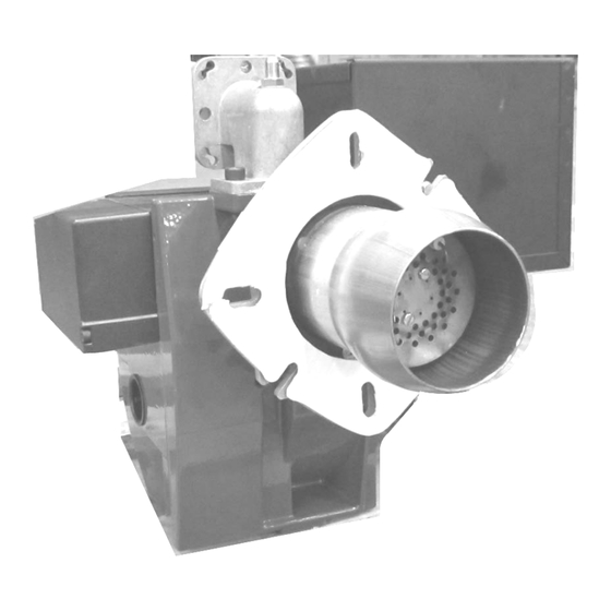
MODEL SU-3 GAS BURNER
Inputs 199,000 thru 399,000 Btu/h
(Inputs 58.32 kW thru 116.94 kW)
1
.
PV500-56 06/12
Advertisement
Table of Contents

Subscribe to Our Youtube Channel
Related Manuals for PVI Industries SU-3

Summary of Contents for PVI Industries SU-3
- Page 1 TO THE OWNER: Retain this manual for future reference. These instructions contain important information that will help you in maintaining and operating this appliance. PVI INDUSTRIES, LLC - Fort Worth, Texas 76111 - Web www.pvi.com - Phone 1-800-433-5654 PV500-56 06/12 ...
-
Page 2: Table Of Contents
TABLE OF CONTENTS 1. Safety Considerations 2. Codes 3. Electrical Specifications 4. Combustion and Ventilation Air 4.1 Equipment Located in Confined Spaces 4.2 Maximum Allowed Remote Combustion Air Inlet Length 4.3 Vertical or Horizontal Remote Air Duct Termination 4.4 Remote Air Consideration for Combined Remote Air Ducting 5. -
Page 3: Safety Considerations
1. SAFETY CONSIDERATIONS WARNING: If the information in these instructions is not followed exactly, a fire or explosion may result, causing property damage, personal injury or death. FOR YOUR SAFETY Do not store or use gasoline or other flammable vapors or liquids in the vicinity of this or any other appliance. WHAT TO DO IF YOU SMELL GAS ... -
Page 4: Codes
Canadian authority having jurisdiction, the equipment must be installed in accordance with the latest edition of the Installation Code for Gas Burner Appliances and Equipment CAN/CSA B149.1 and/or B149.2 and applicable Provincial Regulations. 3. ELECTRICAL SPECIFICATIONS SU-3 Electrical Specifications Primary Electric Input Secondary Electric Input Total Watts... -
Page 5: Combustion And Ventilation Air
The Listed air intake vent termination cap MUST be attached to the remote combustion air vent termination to adequately protect the combustion air inlet from wind and weather. A UL Listed air intake termination cap is available from PVI Industries and may have shipped with the water heater and burner as a purchased option. -
Page 6: Remote Air Consideration For Combined Remote Air Ducting
4.4 Remote Air Consideration for Combined Remote Air Ducting When remote air ducting is used, each water heater burner MUST have separate combustion air intake piping. 5. VENTING For appliances connecting to gas vents or chimneys, vent installation and vent size must be in accordance with Part 7, "Venting of Equipment,"... -
Page 7: Gas Control Trains
6.2 Gas Control Trains - All models include gas control trains with the following components: main manual shutoff valve, two safety shutoff valves and pressure regulator. These components may be separate or two or more may be combined in a common housing. Caution: Do not adjust or remove any screws or bolts on gas train control components which are sealed with a red or blue colored compound. -
Page 8: Appliance Isolation During Gas Supply Piping Pressure
½” psig (3.45 kPa). SU-3 GAS BURNER THIS IS NOT PART OF... -
Page 9: Burner Operation
8. BURNER OPERATION Before placing the burner in service, a qualified installer, service agency or the gas supplier must perform installation and service. All piping must conform with local codes. Do not try to light the burner by hand. Lighting Instructions 1. -
Page 10: Burner Setup And Adjustment
10. BURNER SETUP AND ADJUSTMENT WARNING: The burner supplied with this water heater has been factory adjusted to operate on the type gas, gas pressure, manifold pressure and firing rate identified on the burner data decal and must be verified after installation and adjusted as required to obtain those values. Firing this burner above the burner decal specified firing rate will void the warranty, and may result in improper operation, a fire or explosion, or dangerous carbon monoxide, causing property damage, personal injury or death. -
Page 11: Commissioning Checklist
110 and 125 is shown then the polarity to the burner is reversed.) 4. Check that the orifice is installed. All SU-3 burners, except natural gas burners with inputs above 199,000 btuh (58.32 kW), have an orifice installed in the burner’s gas pipe union. If the required orifice is missing, contact PVI for a proper size replacement. -
Page 12: Burner Operation Record
10.4 Burner Operation Record Note: if any adjustments are made, it is important to recheck the manifold pressure and combustion analysis. Check the following readings in the vent above the flue collector and below the barometric damper. BURNER OPERATION: Record the Readings at Steady State Incoming Static Gas Pressure = “W.C. -
Page 13: Maintenance Instructions
11. MAINTENANCE INSTRUCTIONS At least once a year, a qualified service agency needs to be contracted for other than routine maintenance, including such things as checking the burner head and checking combustion. WARNING: Turn off all electrical service to the appliance when accessing the limit or other controls located inside the appliance or burner control cabinet. -
Page 14: Troubleshooting
12. TROUBLESHOOTING Condition Solutions Burner motor runs and: Check 24V feed to airflow switch & after airflow switch to control. Fix or No flame after pre-purge replace the airflow switch. If there is no secondary power, then replace the 24V transformer. No flame, faulty ignition transformer or spark Check ignition transformer output from Honeywell control and check for separately... -
Page 15: Materials List
13. MATERIALS LIST ITEM Part # PART ITEM Part # PART 118916 Blast Tube 119167 Ionization Cable 101329 Flange Gasket 101630 Ignition Transformer 5734 & (2) 101306 Adjustable Flange Ignition Cable for 2260-TWO 5315 118941 Front piece - Housing 118936 Cover Plate - Air Regulation 119183 Rear piece - Housing... - Page 16 , LLC 3209 Galvez Ave. Fort Worth, Texas 76111 Phone 1-800-433-5654 www.pvi.com ® PVI INDUSTRIES PV500-56 06/12 ...
Need help?
Do you have a question about the SU-3 and is the answer not in the manual?
Questions and answers