Table of Contents
Advertisement
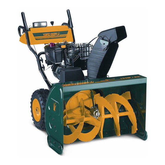
Operator's Manual
Two Stage
Snow Thrower
33" Model Shown
IMPORTANT:
Read safety rules and instructions
carefully
before operating
equipment.
Warning:
This unit is equipped with an internal combustion engine and should not be used on or near any unimproved
forest-
covered, brush-covered
or grass-covered
land unless the engine's exhaust system is equipped with a spark arrester meeting
applicable
local or state laws (if any). If a spark arrester is used, it should be maintained
in effective working order by the operator.
In the State of California the above is required by law (Section 4442 of the California Public Resources Code). Other states may have
similar laws. Federal laws apply on federal lands. A spark arrester for the muffler is available through your nearest engine authorized
service dealer or contact the service department,
P.O. Box 361131 Cleveland, Ohio 44136-0019.
For US Customers: MTD LLC, P.O. BOX361131CLEVELAND,OHIO44136-0019
For Canadian Customers: MTD Products Ltd., P. O. BOX1386, KITCHENEB,ONTARION2G 4J1
PRINTED IN U.S.A.
FORM NO. 769-01206A
(4/2005)
Advertisement
Table of Contents

Subscribe to Our Youtube Channel
Related Manuals for Yard-Man 31AE9P3I801


Summary of Contents for Yard-Man 31AE9P3I801
- Page 1 Operator's Manual Two Stage Snow Thrower 33" Model Shown IMPORTANT: Read safety rules and instructions carefully before operating equipment. Warning: This unit is equipped with an internal combustion engine and should not be used on or near any unimproved forest- covered, brush-covered or grass-covered land unless the engine's exhaust system is equipped with a spark arrester meeting...
- Page 2 TABLEOFCONTENTS Content Page Content Page Customer Support Ajustments Important SafeOperation P ractices Maintenance Assembly Servicing Knowing Y ourSnow Thrower Off-Season Storage Operatiing Y ourSnow Thrower Warranty Illustrated Parts List FINDINGMODELNUMBER This Operator's Manual is an important part of your new snow thrower. It will help you to assemble, prepare and maintain the unit for best performance.
- Page 3 SECTION 1: IMPORTANT SAFEOPERATION P RACTICES WARNING: This symbol points out important safety instructions which, if not followed, could endanger the personal safety and/or property of yourself and others. Read and follow all instructions in this manual before attempting to operate this machine. Failure to comply with these instructions may result in personal injury. When you see this symboliheed its warning.
- Page 4 6. Donot o perate m achine while under theinfluence of MaintenanceAndStorage alcohol ordrugs. Never tamper with safety devices. Check their proper 7. Muffler and engine b ecome hot a nd can cause a burn. Do operation regularly. not t ouch. Disengage the control handle and stop engine.
- Page 5 SECTION 2: ASSEMBLING YOUR SNOW THROWER NOTE: This Operator's Manual covers several models. Assembling Handle Snow thrower features vary model. Not all • Remove the lower plastic wing nut, cupped washer features discussed in this manual are applicable to all and carriage bolt from each side of the lower snow thrower models.
- Page 6 With the hex nuts loosened on the lower chute Attaching theChute Assembly crank bracket (see Figure 5) adjust the bracket so that the spiral on the chute crank fully engages the NOTE: Your chute assembly may or may not be teeth on the chute assembly.
- Page 7 ChuteClean-Out T ool The chute clean-out tool is conveniently fastened to ARNING: Over-tightening Do not over-tighten the cable. may prevent the auger from the rear of the auger housing with a mounting clip. disengaging and compromise the safety of the Use the clean-out tool to clear snow and ice which snow thrower.
- Page 8 Tire Pressure (PneumaticTires) The tires are overinflated for shipping purposes. Coupler • Check tire pressure. Maintain pressure between 10 and 14 psi. Spring NOTE: If the tire pressure is not equal in all tires, the Cable unit may pull to one side or the other. L ock Nut WARNING: Maximum tire pressure under...
- Page 9 ChuteTilt Control AugerControl The distance snow is thrown can be The auger control is located on the left handle. Squeeze the auger changed by adjusting the angle of the control to engage the augers. chute assembly. Move the chute tilt control forward to decrease the Release to stop the snow throwing action.
- Page 10 SECTION 4: OPERATING Y OUR SNOW THROWER BeforeStarting using the electric starter. If you have a grounded three-prong receptacle, Read and understand all instructions and warnings on proceed as follows: the machine and in this manual before operating. Connect power cord to switch box on engine. Plug the other end of power cord into a three-hole, Gas&...
- Page 11 loud clattering sound, which is not harmful to the If possible, remove snow immediately after it falls. engine or starter. Discharge snow downwind whenever possible. Move throttle control to "stop" or "off" position. Slightly overlap each previous path. Remove ignition key. Do not turn key. Disconnect Set the skid shoes 1/4"...
- Page 12 SECTION 5: MAKING ADJUSTMENTS • Tip the snow thrower forward, allowing it to rest on the auger housing. ARNING" • Remove the frame cover underneath the snow NEVER attempt to clean chute or make any adjustments while engine is running. thrower by removing six self-tapping screws.
- Page 13 SkidShoe The space between the shave plate and the ground can be adjusted by raising or lowering the skid shoes. For close snow removal, as when using on a smooth concrete or asphalt driveway, place the skid shoes in the low position. Use the middle or high position when the area to be cleared is uneven.
- Page 14 Wheel DriveControl / AugerControl Lock The cams on the ends of the control rods which interlock the wheel drive and auger drive controls must be Shear Pin Vent Plug lubricated at least once a season or every 25 hours of Cotter Pin operation using a multi-purpose automotive grease.
- Page 15 SECTION 7: SERVICING YOUR SNOW THROWER Replacing Belts • Disconnect the chute crank assembly at the ARNING" Before servicing, repairing, or inspecting, disengage all clutch levers and stop discharge chute end by removing the hairpin clip engine. Wait until all moving parts have come and the flat washer.
- Page 16 Drive Belt • Unhook the extension spring from the belt cover plate. See Figure 23. • Remove drive belt from the engine pulley and Engine Pulley bottom drive pulley. • Replace belt and reassemble in reverse order. Brake Bracket Assembly _uger Belt Idler Pulley...
- Page 17 Changing Friction WheelRubber • Insert the pin from the shift arm assembly into the friction wheel assembly and hold assembly in The rubber on the friction wheel is subject to wear and position. Refer to Figure 24. should be checked after the first 25 hours of operation, and periodically thereafter.
- Page 18 SECTION 8: 0FF-SEASON STORAGE • Remove all debris from the exterior of equipment. • Follow lubrication recommendations on page 13. ARNING" Never store engine with fuel in tank indoors or in poorly ventilated areas, • Always store the snow thrower in a clean, dry area. where fuel fumes may reach an open flame, NOTE: When storing any type of power equipment in spark or pilot light as on a furnace, water...
- Page 19 MANUFACTURER'S LIMITED WARRANTY FOR: YaRD.MaN ® The limited warranty setforth below is given by MTD LLC with Service completed by someone other than an authorized service dealer. respectto new merchandise purchasedand used in the United States and/or its territories and possessions,and by MTD Products Limited MTD does not extend any warranty for products sold or with respectto new merchandise purchasedand used in Canadaand/ exported outside of the United States and/or Canada,...
- Page 20 Flats (#6) parallel to rear when installing engagement handles in the engaged position as shown./ Placez les parties plates (#6) paraflelernent a I'arriere lots de I'installation des manettes d'enclenchement a la position engagee (representee). Forinformation onlights andhandle panels r efer t opages 3 0and31 Voir /es pages 30 et 31 pour tout renseignement concernant le tableau de...
- Page 21 PART N ° DE N ° DE PIECE DESCRIPTION DESCRIPTION 720-0232 Shift Knob Bouton 710-0351 Vis de renforcement taraudee no. 10-16 x 0,50 Qual.5 Truss Mach B-Tapp Scr #10-16 x .50 Gr. 5 705-5218 Poignee d'entraTnement CD noir Engagement Handle RH Black 705-5219 Poignee d'entratnement CG noir...
- Page 22 Torque to 20-30 in./Ibs./ Serrez a un couple de 20-30 po-/b. "31 Shave plate should ride slightly above ashpalt. Set to maximum for gravel driveways./ La plaque de r_c/age dolt _tre legerement au-dessus du goudron. Reglez-/a au maximum en cas d'aflees graviflonnees. When rebuilding gear box fill g half completely with grease 838-0168./Pour...
- Page 23 PART N° DE N° DE PII_CE DESCRIPTION DESCRIPTION 736-0159 Flat Washer .344 ID x .875 OD Rondelle plate 0,344 DI x 0,875 DE 710-0597 Hex. Scr. 1/4-20 x 1.00 Gr. 5 Vis &t_te hex. 1/4-20 x 1,00 po de Ig. Qual. 5 736-0169 Lockwasher 3/8"...
- Page 24 N° DE N° DE RI_F PII_CE DESCRIPTION DESCRIPTION 618-0247 Gear Housing Half LH Carter d'engrenages - moiti6 - gauche 618-0435 Gear Housing Half LH (w/grease fitting hole Carter d'engrenages - moiti6 - gauche (avec trou pour raccord graisse) 710-1260A Hex Flange Scr. 5/16-18 x .75 Vis &...
- Page 25 Torque to 21 ft./Ibs, max- imum, cupped washer should be flat./ Serrez a un couple de 21 ..-_ pHb maximum. La PART N° DE N° DE PII_CE DESCRIPTION DESCRIPTION 712-0717 Ecrou ins@er 3/8-16 UNC Nut Insert 3/8-16 UNC 712-04063 Hex Fig.
- Page 26 _--_s _j81 _, o4...
- Page 27 PART N° DE N° DE PIECE RI_F DESCRIPTION DESCRIPTION 618-0279 LH Dog Assembly Bride gauche 618-0280 Bride droite RH Dog Assembly 618-0282D Arbre de direction Steering Shaft Assembly 618-04178 Wheel Ass'y Bearing 6.0" OD Roulement 6,0 po diam. Friction Wheel Bonded Roue de friction 718-04034 710-0896...
- Page 28 PART N °DE N° DE PIECE DESCRIPTION DESCRIPTION 741-04025 Self aligning brg. 1.0 ID Palier A alignement automatique 741-0225 Hex Flange Bearing .630 ID Roulement & bride hex de 0,630 DI 741-0563 Ball Bearing w/snap ring Roulement a billes avec bague 741-04076 Ball Bearing .5625 ID x 1.3750 x .437 Roulement &...
- Page 29 Engine is for reference only and may not resemble the en- gine on your snowthrower. Le moteur est represente a ti- tre indicatif seu/ement et peut Re pas resembler au moteur de votre souffleuse. Torque to 325-550 in.lbs./ Couple de 325-550 po-lb. Torque to 200-450 in.lbs./ Couple de 200-450 po-lb.
- Page 30 Hole for mounting heated grip toggle switch./Trou de montage du Chute tilt cut-out/ commutateur a culbuteur pour Ouvertures pour goulotte incfinable. poignees chauffees. STYLE 3 STYLE 6 _ _38 2 Attache to loose hangine wire under fuel tank on engine./ 5 8"___ "- ._ /_ attacher au fil metallique qui...
- Page 31 PART N° DE N° DE REF. Pll_CE DESCRiPTiON DESCRiPTiON STYLE3 731-1737A Black Handle Panel (*) Panneau-noir (*) 731-0061 Black Handle Panel (,,,,) Panneau-noir (i.,) 731-1873A Yellow Handle Panel (g=) Panneau4aune (l=) 731-2564 Yellow Handle Panel (+) Panneau4aune (+) 731-2606 Black Handle Panel (**) Panneau-noir (**) STYLE 6 731-2516...
Need help?
Do you have a question about the 31AE9P3I801 and is the answer not in the manual?
Questions and answers