Advertisement
Table of Contents
Advertisement
Table of Contents

Related Manuals for Samson XM610


Summary of Contents for Samson XM610
- Page 1 XM610 SIX CHANNEL POWERED MIXER WITH 24BIT DIGITAL EFFECTS...
-
Page 2: Introduction
Safety Instructions/Consignes de sécurité/Sicherheitsvorkehrungen/Instrucciones de seguridad WARNING: To reduce the risk of fire or electric shock, do not expose this unit to ATTENTION: Pour éviter tout risque d’électrocution ou d’incendie, ne pas rain or moisture. To reduce the hazard of electrical shock, do not remove cover or exposer cet appareil à... -
Page 3: Table Of Contents
Table of Contents Introduction XM610 Features Controls and Functions Front Panel Layout Front Panel Controls 5–9 XM610 Input and Output Connections 10–12 Operating the XM610 13–15 System Set-ups 16–17 XM610 Wiring Guide Specifications Block Diagram Copyright 2004, Samson Technologies Corp. -
Page 4: Xm610 Features
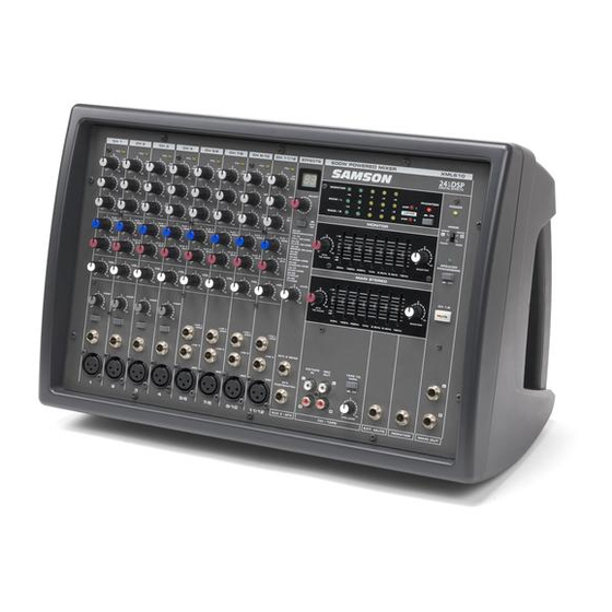
XM610 Features The Samson XM610 Powered Mixer is a comprehensive, all-in-one mixer / power amplifier solution for live sound applications. Here are some of its main features: • Six channel powered mixer in ergonomically correct kickback enclosure allowing you to easily see and operate the front panel functions. - Page 5 In these pages, you’ll find a detailed description of the features of the XM610 powered mixer, as well a description of its front and rear panels, step-by-step instructions for its setup and use, and full specifications.
-
Page 6: Controls And Functions
Controls and Functions FRONT PANEL LAYOUT... -
Page 7: Front Panel Controls
AMP select switch is set to MAIN+MONITOR. AUX 2 / EFX Effects Send The XM610 provides high quality, 24 Bit digital effects, and the level of effects can be set independently on each channel. The channel’s EFX (Effects) knob controls the amount of signal that is sent to the EFX bus. - Page 8 FRONT PANEL CONTROLS 24 BIT DIGITAL EFFECT SECTION The XM610 features a built-in, 24 Bit Digital Effects processor with 100 high quality, studio grade effects like Delay, Chorus and Reverb. The following sec- tion describes the features of the powerful on-board digital effects section.
-
Page 9: Power Amp Section
BRIDGE. The following is a description of each of the POWER operating modes: CAUTION! Only change the power amp mode switch when the XM610’s power is SWITCHED OFF! MAIN-MONITOR With this setting, the MAIN and MONITOR sections can be used independently. The MAIN bus signal will be sent from the POWER AMP 2 A/B jacks, and the MONITOR bus signal will be sent from the POWER AMP 1 A/B jacks. -
Page 10: Main Section
Controls and Functions FRONT PANEL CONTROLS MAIN SECTION The XM610 has two internal power amplifiers and depending on the power amp MODE selection switch, the amplifiers are sent the MAIN or MONI- TOR bus signal. The following section describes the... -
Page 11: Front Panel Controls
Controls and Functions FRONT PANEL CONTROLS MONITOR SECTION The XM610 has two internal power amplifiers and depending on the MODE selection switch, the ampli- fiers received their input signals from the MAIN or MONITOR bus. The following section describes the... -
Page 12: Xm610 Input And Output Connections
CHANNEL 1–6 MIC and LINE INPUTS The XM610’s six input channels each have a LINE level, Hi-Z (High Impedance) input and a MIC level, Low-Z (Low impedance) input. By using the PAD switches, you can connect a variety of signal sources from micro- phones to line level devices such as synthesizers, drum machines and direct boxes. -
Page 13: Rear Panel
XM610 Input and Output Connections EXTERNAL OUTPUT JACKS The XM610 features several output connectors allowing you to interface a variety of external devices. A stereo recording device such as a cassette recorder can be connected to the REC OUT jacks, and additional power amplifiers can be connected to the MONITOR and MAIN output jacks. - Page 14 MODE switch, see the section POWER AMP SECTION on page 7 of this manual. There are three ways in which speakers can be connected to the XM610: A single speaker can be connected to either the A or B jack of AMP 1 and AMP 2, two speakers can be connected in parallel to both the A and B jacks of AMP1 and AMP 2, or a single speaker can be connected to the BRIDGE jack (bridge connection).
-
Page 15: Operating The Xm610
Operating the XM610 BASIC OPERATION The following section explains the basic operation of the XM610. CONNECTING MICROPHONES AND INSTRUMENTS 1. Before connecting mics or instruments, make sure that the power of all your sys- tems components, including the XM610, is turned off. Also, make sure that the... - Page 16 5. Now use the EFX RTN knob in the MAIN/MONITOR section to adjust the EFFECTS Return level. The EFX control is the overall level control for the DSP effects processor. If you are not using the XM610 in MAIN/ MON- ITOR or BRIDGE mode, be sure to raise the EFX RTN control up on both the MAIN and MAIN/ MONITOR sec- tions so the level of effect is the same in both speakers.
- Page 17 Operating the XM610 USING AN EXTERNAL EFFECT If you prefer to use an external device for effects process- ing, you can easily connect the unit using the XM610 EFX bus. Follow the simple steps below to interface your processor: 1. Set the MONITOR section VOLUME control to the "0"...
-
Page 18: System Set-Ups
XM610 System Set-Ups FLOW SIGNAL FLOW SIGNAL FLOW SIGNAL FLOW SIGNAL FLOW SIGNAL FLOW SIGNAL... - Page 19 XM610 System Set-Ups...
-
Page 20: Xm610 Wiring Guide
XM610 Wiring Guide CONNECTING THE XM610 The are several ways to interface the XM610 to support a variety of applications. The XM610 features balanced inputs and outputs, so connecting balanced and unbalanced signals is possible. Unbalanced 1/4” Connector Balanced TRS 1/4” Connector... -
Page 21: Specifications
Specifications SPECIFICATIONS Rated Output power 300W/4Ω@0.1% THD at 1KHz per amplifier Frequency response 20Hz~20KHz+/-0.5dB@1W Output into 8Ω (AMP OUT) 20 Hz~20KHz+/-0.4@+4dB Output into 10kΩ (MAIN OUT, MONITOR OUT, AUX 2 SEND) Total Harmonic Distortion Less than 0.06%@20Hz~20KHz, 75W output into4Ω (AMP OUT) Less than 0.1%@20 Hz~20KHz+14dB output into 10KΩ... -
Page 22: Block Diagram
Block Diagram... - Page 24 Samson Technologies Corp. 575 Underhill Blvd. P.O. Box 9031 Syosset, NY 11791-9031 Phone: 1-800-3-SAMSON (1-800-372-6766) Fax: 516-364-3888 www.samsontech.com...
Need help?
Do you have a question about the XM610 and is the answer not in the manual?
Questions and answers