Table of Contents
Advertisement
Quick Links
See also:
User Manual
Advertisement
Table of Contents

Summary of Contents for RME Audio MADI Bridge
- Page 1 User's Guide MADI Bridge The MADI Patchbay 8 x 64 Channel MADI Switcher / Router 6 coaxial Inputs and Outputs 2 optical Inputs and Outputs MIDI Remote Control Preset Memory 64 Dot Matrix Display Firmware 1.1 or up...
-
Page 2: Table Of Contents
Software MIDI Remote 8.1 MIDI Control of the MADI Bridge ..............8 8.2 General Notes on Operation................8 8.3 Brief Description of the menu entries, Function MADI Bridge Matrix....9 Configuration Examples 9.1 Distribution 1 to 8..................10 9.2 Pass On Mode ....................10 9.3 Conversion Optical to Coaxial and vice versa .......... -
Page 3: Introduction
1. Introduction The MADI Bridge provides you with a versatile and powerful 8 x 8 patchbay for MADI signals. As a consequent continuation of RME's world-wide successful MADI series, the MADI Bridge also contains elaborate technology and the latest integrated circuits. In a few words: The MADI Bridge is a uniquely powerful and high-quality device, which will excite you even after many years of operation. -
Page 4: Technical Specifications
Output voltage 600 mVpp Cable length: more than 100 m Optical via FDDI duplex SC connector 62.5/125 and 50/125 compatible Fiber length: more than 500 m MIDI 16 channels MIDI 5-pin DIN jack Fixed MIDI Thru functionality User's Guide MADI Bridge © RME... -
Page 5: First Usage
6. First Usage 6.1 Quick Start The user interface of the MADI Bridge is characterized by a clearly structured architecture and an unambiguous labelling of the front and rear sides. The device can thus be used easily with- out a manual, because numerous displays show the state of the device in a strictly logical way. -
Page 6: Operation
Therefore, in most cases this kind of connection makes no sense. As such a connection might be desired in specific cases (see chapter 9.1), it is still available in the MADI Bridge. User's Guide MADI Bridge © RME... -
Page 7: Inputs And Outputs
7.3 MIDI Input and Output The rear of the MADI Bridge offers one MIDI input and output via two 5-pin DIN jacks. The MIDI input can be used to remote control the MADI Bridge. The MADI Bridge sends out status information via the MIDI output. -
Page 8: Software Midi Remote
Furthermore, on request the complete status is send back, which includes all front panel displays and key states. Each MADI Bridge can be programmed with its own ID. This allows to remote control multiple units, even via the same MIDI channel. A de- tailed description of the MIDI commands can be found in chapter 13. -
Page 9: Brief Description Of The Menu Entries, Function Madi Bridge Matrix
So the current window position will not change. Options – Program Device ID Opens a settings dialog to program a device ID into the MADI Bridge. Note: programming is fast and not confirmed. Attention: Programming is only possible when not more than one MADI Bridge is connected via MIDI! User's Guide MADI Bridge ©... -
Page 10: Configuration Examples
9.3 Conversion Optical to Coaxial and vice versa Of course, the MADI Bridge can also serve as format converter from coaxial to optical, and at the same time from optical to coaxial. Thanks to its two optical I/Os, both functions are even... -
Page 11: Technical Background Madi Basics
2 km. Single mode allows for much longer distances, but it uses a completely different fibre (8 µm). By the way, due to the wave-length of the light being used (1300 nm), the opti- cal signal is invisible to the human eye. User's Guide MADI Bridge © RME... -
Page 12: Madi Bridge Technology
3348 (digital tape machine of the first MADI generation) becomes unreadable when passed through the MADI Bridge. Fortunately this problem was easy to be fixed. The inputs 5 and 6 of the MADI Bridge can be made compatible to the 3348 by internal jumpers. -
Page 13: Controls And Connectors
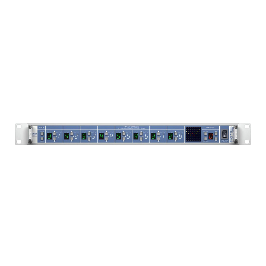
Front Right Part Input selection Input selection Preset section Power switch Matrix display for Output 6 for Output 8 Store Recall Select Rear Power connector MADI Optical MADI coaxial MIDI Inputs Inputs Input Outputs Outputs Output User's Guide MADI Bridge © RME... -
Page 14: Block Diagram
12. Block Diagram User's Guide MADI Bridge © RME... -
Page 15: Midi Implementation Chart
/ oo can be repeated freely. 13.3 Total Reset Sending the following SysEx string to the MADI Bridge will perform a complete reset (factory default state). Device ID is set to 00, all presets are set to 0 (no connection active in any pre- set), and preset NONE is selected. -
Page 16: Table
27h Preset 3 Out 8 Same 28h Preset 4 Out 1 Same 29h Preset 4 Out 2 Same 2Ah Preset 4 Out 3 Same 2Bh Preset 4 Out 4 Same 2Ch Preset 4 Out 5 Same User's Guide MADI Bridge © RME... - Page 17 4Ah Preset 8 Out 3 Same 4Bh Preset 8 Out 4 Same 4Ch Preset 8 Out 5 Same 4Dh Preset 8 Out 6 Same 4Eh Preset 8 Out 7 Same 4Fh Preset 8 Out 8 Same User's Guide MADI Bridge © RME...
- Page 18 59h Current Out 2 Same 5Ah Current Out 3 Same 5Bh Current Out 4 Same 5Ch Current Out 5 Same 5Dh Current Out 6 Same 5Eh Current Out 7 Same 5Fh Current Out 8 Same User's Guide MADI Bridge © RME...
-
Page 19: Warranty
Matthias Carstens, 01/2005. Version 1.0 Although the contents of this User’s Guide have been thoroughly checked for errors, RME can not guarantee that it is correct throughout. RME does not accept responsibility for any misleading or incorrect information within this guide. Lending or copying any part of the guide or the RME Driver CD, or any commercial exploitation of these media without express written permission from RME Intelligent Audio Solutions is prohibited. - Page 20 Use power outlets on different branch circuits, or install AC line filters Contact your local retailer or any qualified radio and television engineer FCC compliance statement: Tested to comply with FCC standards for home or office use. User's Guide MADI Bridge © RME...
Need help?
Do you have a question about the MADI Bridge and is the answer not in the manual?
Questions and answers