
Related Manuals for Honda WSP33AA


Summary of Contents for Honda WSP33AA
- Page 1 OPERATOR'S MANUAL SUBMERSIBLE PUMP WSP33AA•WSP53AA•WSP73AA POM31WSP611 AHM.2000.2011.02 © 2004-2011 American Honda Motor Co., Inc. All Rights Reserved Printed in USA...
- Page 2 Thank you for purchasing this Honda Stainless Steel Sump Pump. We hope you are pleased with your purchase and that our pumps will provide you with long service life and exceptional performance. To ensure satisfactory service life, there are several considerations regarding proper installation, operation, and power source.
- Page 3 Important Safeguards To reduce risk of injury, always follow these instructions and safety precautions when using this pump and to maintain warranty. Read All Instructions Prior to Installation (SAVE THESE INSTRUCTIONS) Installation/Operation • Never lift or carry the pump by the electrical cord. Use a chain or rope affixed to the handle to install or remove the pump.
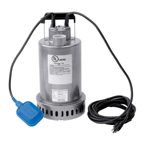
- Page 4 Proper Lifting A separate chain or rope should be attached to the handle for normal lifting. Note that this will help prevent damage due to inadvertent lifting of the pump by the power cord. Rope attached to the automatic pump for lifting and installation.
-
Page 5: Table Of Contents
Honda recommends that a solid sump base be provided. The sump is fed by drain tile placed around the outside and/or inside basement walls at the footings. In... -
Page 6: Electrical Installation
Electrical Installation Electrical service for any sump pump installation must be grounded and separately fused or breakered directly from the entrance box with a single grounding type receptacle at the pump. The receptacle should not be less than four feet above the basement floor for safety reasons. -
Page 7: Safety Information And Introduction
Basin and Cover The basin should not be less than 18 inches in diameter and 24 inches deep. Larger diameters are advisable in instances of increased pump capacity requirements: Required Pump Capacity Minimum Basin Diameter Up to 35 GPM 18" Over 35 GPM 24"... -
Page 8: General Specifications
General Specifications B CAUTION Be careful not to exceed the given specifications in the use of your products. Check the nameplate for your pump’s head (HEAD), discharge volume (CAPACITY), speed (SPEED), motor voltage, and current. Other specifications are noted in the chart below: Discharge Motor... -
Page 9: Installation Instructions
Installation Instructions Step 1. Carefully inspect the pump for damage that could cause it to fail. Your pump has been carefully packaged to prevent damage during shipping; however, occasional damage does occur due to rough handling. Step 2. Attach the desired length of PVC or ABS discharge pipe to the pump outlet, using PVC adapter (1-1/4"... -
Page 10: Electrical Information
Before installing the pump, clear the sump basin of any water, debris, or sediment. WARNING: The sump basin must be vented in accordance with local plumbing codes. Honda WSP pumps are not designed for and CANNOT be installed in locations classified as hazardous in the National Electric Code, ANSI/NFPA 70. -
Page 11: Submersible Pump Installation
Be certain the sump basin is clean and all power to the pump is shut off. If the pump fails to operate properly after installation, refer to “Troubleshooting Checklist” on page 16 or contact a Honda servicing dealer. General Materials Needed • One can of PVC cement (read the instructions carefully) •... -
Page 12: Performance Table (Capacity In Gallons Per Minute)
Step 5. Plug in the pump and fill the sump basin with water. The pump should turn on when the water level reaches 13'' to 14''. If it does not turn on at the 13'' to 14'' water level, remove the float cord from the clip and re-attach it in a higher or lower position so that the pump turns on at the 13'' to 14'' water level. -
Page 13: Wsp Submersible Pump Installation Diagram
Shut-off gate for 1-1/4" and 1-1/2" pipe valve (optional) *All equipment other than pump to be supplied by others. Pump only supplied by Honda. 10-1/2" Min. Sump basin 18" to 24" dia. plastic, fiberglass, or concrete Discharge piping can be PVC or... -
Page 14: Motor Wiring Diagram
Motor Wiring Diagram WSP33K1 Automatic Operation Type Output (Single Phase) MOTOR Black Green Brown White Gray Yellow/Green... - Page 15 WSP53/WSP73 Automatic Operation Type Output (Single Phase) PROTECT TERM MOTOR Black White Blue Yellow/Green Green...
-
Page 16: Operation
Operation Check the water level before starting the pump. If the pump is operated continuously for an extended period of time in a dry condition or at the lowest water level, the motor protector will be activated in single phase units. Constant repetition of this action will shorten pump service life. -
Page 17: Technical Specifications
Technical Specifications Model WSP33K1AA WSP53AA WSP73AA Performance: ISO 2548 Item Standard Discharge Size 1-1/4 inch (WSP33K1AA) 1-1/2 inch (WSP53AA, WSP73AA) Range of Performance Capacity: up to 74 GPM Head: up to 54 feet Maximum water 122°F/50°C temperature Solids 3/8 in spherical (2% by concentration) Speed 3600 RPM Materials... -
Page 18: Troubleshooting Checklist
Troubleshooting Checklist Problem Possible Causes Pump does • Line circuit breaker is off, or fuse is blown or loose. not run or • Water level in the sump has not reached turn-on level as hums indicated in the installation drawing. •... -
Page 19: Maintenance And Service
Problem Possible Causes Motor runs for • Inlet holes in pump base are clogged. Remove pump and clean the openings. a short time, • Pump impeller is partially clogged, causing motor to run slow then stops and overload. Remove pump and clean. •... -
Page 20: Sectional View - Wsp33K1Aa
Sectional View – WSP33K1AA Automatic Type Output 1/3 HP (Single Phase) - Page 21 Ref No. Part Name Material Standard Quantity Suction cover EN 1.4301 (AISI 304) — Casing cover EN 1.4301 (AISI 304) — Shaft with rotor EN 1.4305 (AISI 303) — Impeller PPE+PS-HI-GF20 — Mechanical seal — — Motor frame with stator EN 1.4301 (AISI 304) —...
-
Page 22: Sectional View - Wsp53Aa, Wsp73Aa
Sectional View – WSP53AA, WSP73AA Automatic Type Output 1/2 to 3/4 HP (Single Phase) Ref No. Part Name Material Code No. for 1 Unit Outer Casing 304 Stainless AISI 304 Suction Cover 304 Stainless AISI 304 Seal Cover 304 Stainless AISI 304 Impeller 304 Stainless... -
Page 23: Disassembly And Assembly
Disassembly and Assembly Disassembly When disassembling the pump, have a piece of cardboard or wooden board ready to place the different parts on as you work. Do not pile parts on top of each other. They should be laid out neatly in rows. The O-ring and gasket cannot be used again once they are removed. -
Page 24: Customer Service Information
Manager, General Manager, or Owner can help. Almost all problems are solved in this way. If you are dissatisfied with the decision made by the dealership's management, you may contact the Honda Power Equipment Customer Relations Office. You can write to: American Honda Motor Co., Inc. Power Equipment Division... - Page 25 WSP33AA WSP53AA Printed on WSP73AA P/N 31WSP611 Recycled Paper...
Need help?
Do you have a question about the WSP33AA and is the answer not in the manual?
Questions and answers