
Related Manuals for Gigabyte GA-EP31-DS3L


Summary of Contents for Gigabyte GA-EP31-DS3L
- Page 1 GA-EP31-DS3L LGA775 socket motherboard for Intel Core processor family/ ® Intel Pentium processor family/Intel Celeron processor family ® ® ® ® User's Manual Rev. 1002 12ME-EP31DS3L-1002R...
-
Page 3: Identifying Your Motherboard Revision
GIGABYTE's prior written permission. Documentation Classifications In order to assist in the use of this product, GIGABYTE provides the following types of documentations: For quick set-up of the product, read the Quick Installation Guide included with the product. -
Page 4: Table Of Contents
Table of Contents Box Contents ......................... 6 Optional Items......................... 6 GA-EP31-DS3L Motherboard Layout ................7 Block Diagram........................ 8 Chapter 1 Hardware Installation ..................9 Installation Precautions ..................9 Product Specifications ..................10 Installing the CPU and CPU Cooler .............. 13 1-3-1 Installing the CPU .................... - Page 5 Chapter 3 Drivers Installation ..................53 Installing Chipset Drivers ................53 Software Applications ..................54 Driver CD Information ..................54 Hardware Information ..................55 Contact Us ..................... 55 Chapter 4 Unique Features ..................57 Xpress Recovery2 ..................57 BIOS Update Utilities ..................62 4-2-1 Updating the BIOS with the Q-Flash Utility ............
-
Page 6: Box Contents
Box Contents GA-EP31-DS3L motherboard Motherboard driver disk User's Manual Quick Installation Guide One IDE cable and one floppy disk drive cable Two SATA 3Gb/s cables I/O Shield • The box contents above are for reference only and the actual items shall depend on product package you obtain. The box contents are subject to change without notice. -
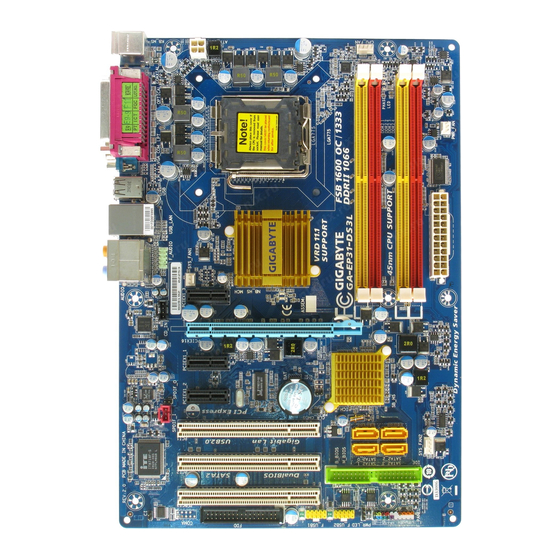
Page 7: Ga-Ep31-Ds3L Motherboard Layout
GA-EP31-DS3L Motherboard Layout CPU_FAN KB_MS ATX_12V COAXIAL LGA775 OPTICAL PWR_FAN Intel ® AUDIO SYS_FAN1 PCIE_3 PCIE_16 RTL8111B PCIE_1 CODEC PCIE_2 Intel ICH7 ® SPDIF_I PCI1 SATAII0 SATAII2 SYS_FAN2 BIOS PCI2 SATAII1 SATAII3 IDE1 PCI3 PWR_LED F_PANEL F_USB2 F_USB1 - 7 -... -
Page 8: Block Diagram
Block Diagram PCIe CLK CPU CLK+/- (100 MHz) LGA775 (333/266/200 MHz) Processor 1 PCI Express x16 Host Interface DDR2 1066/800/667 MHz Dual Channel Memory PCI Express x16 Intel ® MCH CLK (333/266/200 MHz) RJ45 8111B BIOS PCI Express Bus ATA-100/66/33 IDE Channel 3 PCI Express x1 4 SATA 3Gb/s... -
Page 9: Chapter 1 Hardware Installation
Chapter 1 Hardware Installation Installation Precautions The motherboard contains numerous delicate electronic circuits and components which can become damaged as a result of electrostatic discharge (ESD). Prior to installation, carefully read the user's manual and follow these procedures: Prior to installation, do not remove or break motherboard S/N (Serial Number) sticker or •... -
Page 10: Product Specifications
® ® Intel Celeron processor in the LGA 775 package ® ® (Go to GIGABYTE's website for the latest CPU support list.) L2 cache varies with CPU Front Side Bus 1333/1066/800 MHz FSB Chipset North Bridge: Intel P31 Express Chipset ®... - Page 11 Internal Connectors 1 x 24-pin ATX main power connector 1 x 4-pin ATX 12V power connector 1 x floppy disk drive connector 1 x IDE connector 4 x SATA 3Gb/s connectors 1 x CPU fan header 2 x system fan headers 1 x power fan header 1 x front panel header 1 x front panel audio header...
- Page 12 Unique Features Support for @BIOS Support for Download Center Support for Q-Flash Support for EasyTune (Note 3) Support for Xpress Install Support for Xpress Recovery2 Support for Virtual Dual BIOS Support for Dynamic Energy Saver (Note 4) Bundled Software Norton Internet Security (OEM version) Operating System Support for Microsoft Windows...
-
Page 13: Installing The Cpu And Cpu Cooler
Read the following guidelines before you begin to install the CPU: • Make sure that the motherboard supports the CPU. (Go to GIGABYTE's website for the latest CPU support list.) • Always turn off the computer and unplug the power cord from the power outlet before installing the CPU to prevent hardware damage. - Page 14 B. Follow the steps below to correctly install the CPU into the motherboard CPU socket. Before installing the CPU, make sure to turn off the computer and unplug the power cord from the power outlet to prevent damage to the CPU. CPU Socket Lever Step 1: Step 2:...
-
Page 15: Installing The Cpu Cooler
1-3-2 Installing the CPU Cooler Follow the steps below to correctly install the CPU cooler on the motherboard. (The following procedure uses Intel boxed cooler as the example cooler.) ® Male Push Pin Direction of the Arrow Sign on the Male The Top Push Pin of Female... -
Page 16: Installing The Memory
• Make sure that the motherboard supports the memory. It is recommended that memory of the same capacity, brand, speed, and chips be used. (Go to GIGABYTE's website for the latest memory support list.) • Always turn off the computer and unplug the power cord from the power outlet before installing the memory to prevent hardware damage. -
Page 17: Installing A Memory
1-4-2 Installing a Memory Before installing a memory module , make sure to turn off the computer and unplug the power cord from the power outlet to prevent damage to the memory module. DDR2 DIMMs are not compatible to DDR DIMMs. Be sure to install DDR2 DIMMs on this motherboard. -
Page 18: Installing An Expansion Card
Installing an Expansion Card Read the following guidelines before you begin to install an expansion card: • Make sure the motherboard supports the expansion card. Carefully read the manual that came with your expansion card. • Always turn off the computer and unplug the power cord from the power outlet before installing an expansion card to prevent hardware damage. -
Page 19: Back Panel Connectors
Back Panel Connectors PS/2 Keyboard and PS/2 Mouse Port Use the upper port (green) to connect a PS/2 mouse and the lower port (purple) to connect a PS/2 keyboard. Parallel Port Use the parallel port to connect devices such as a printer, scanner and etc. The parallel port is also called a printer port. - Page 20 Center/Subwoofer Speaker Out Jack (Orange) Use this audio jack to connect center/subwoofer speakers in a 5.1/7.1-channel audio configuration. Rear Speaker Out Jack (Black) Use this audio jack to connect rear speakers in a 4/5.1/7.1-channel audio configuration. Side Speaker Out Jack (Gray) Use this audio jack to connect side speakers in a 7.1-channel audio configuration.
-
Page 21: Internal Connectors
Internal Connectors ATX_12V F_AUDIO F_PANEL CPU_FAN CD_IN SYS_FAN1 SPDIF_I SYS_FAN2 SPDIF_O PWR_FAN F_USB1/F_USB2 IDE1 CLR_CMOS SATAII0/1/2/3 PWR_LED PHASE LED Read the following guidelines before connecting external devices: • First make sure your devices are compliant with the connectors you wish to connect. •... - Page 22 1/2) ATX_12V/ATX (2x2 12V Power Connector and 2x12 Main Power Connector) With the use of the power connector, the power supply can supply enough stable power to all the components on the motherboard. Before connecting the power connector, first make sure the power supply is turned off and all devices are properly installed.
- Page 23 3/4/5/6) CPU_FAN/SYS_FAN1/SYS_FAN2/PWR_FAN (Fan Headers) The motherboard has a 4-pin CPU fan header (CPU_FAN), a 4-pin system fan header (SYS_FAN2), a 3-pin system fan header (SYS_FAN1), and a 3-pin power fan header (PWR_FAN). Each fan header supplies a +12V power voltage and possesses a foolproof insertion design. When connect- ing a fan cable, be sure to connect it in the correct orientation.
- Page 24 8) IDE1 (IDE Connector) The IDE connector supports up to two IDE devices such as hard drives and optical drives. Before attaching the IDE cable, locate the foolproof groove on the connector. If you wish to connect two IDE devices, remember to set the jumpers and the cabling according to the role of the IDE devices (for example, master or slave).
-
Page 25: Front Panel Audio Header
10) PWR_LED (System Power LED Header) This header can be used to connect a system power LED on the chassis to indicate system power status. The LED is on when the system is operating. The LED keeps blinking when the system is in S1 sleep state. -
Page 26: F_Panel
12) F_PANEL (Front Panel Header) Connect the power switch, reset switch, speaker and system status indicator on the chassis front panel to this header according to the pin assignments below. Note the positive and negative pins before connecting the cables. Message/Power/ Power Speaker... - Page 27 13) CD_IN (CD In Connector, Black) You may connect the audio cable that came with your optical drive to the header. Pin No. Definition CD-L CD-R 14) SPDIF_I (S/PDIF In Header, Red) This header supports digital S/PDIF in and can connect to an audio device that supports digital audio out via an optional S/PDIF in cable.
- Page 28 15) SPDIF_O (S/PDIF Out Header) This header supports digital S/PDIF out and connects a S/PDIF digital audio cable (provided by expansion cards) for digital audio output from your motherboard to certain expansion cards like graphics cards and sound cards. For example, some graphics cards may require you to use a S/PDIF digital audio cable for digital audio output from your motherboard to your graphics card if you wish to connect an HDMI display to the graphics card and have digital audio output from the HDMI display at the same time.
-
Page 29: Chassis Intrusion Header
17) CI (Chassis Intrusion Header) This motherboard provides a chassis detection feature that detects if the chassis cover has been removed. This function requires a chassis with chassis intrusion detection design. Pin No. Definition Signal 18) CLR_CMOS (Clearing CMOS Jumper) Use this jumper to clear the CMOS values (e.g. - Page 30 19) BAT(Battery) The battery provides power to keep the values (such as BIOS configurations, date, and time information) in the CMOS when the computer is turned off. Replace the battery when the battery voltage drops to a low level, or the CMOS values may not be accurate or may be lost. You may clear the CMOS values by removing the battery: 1.
-
Page 31: Chapter 2 Bios Setup
To see more advanced BIOS Setup menu options, you can press <Ctrl> + <F1> in the main menu of the BIOS Setup program. To upgrade the BIOS, use either the GIGABYTE Q-Flash or @BIOS utility. Q-Flash allows the user to quickly and easily upgrade or back up BIOS without entering the •... -
Page 32: Startup Screen
Startup Screen The following screens may appear when the computer boots. A. The LOGO Screen (Default) Function Keys <TAB>:POST Screen <DEL>:BIOS Setup/Q-Flash <F9>:XpressRecovery2 <F12>:Boot Menu <END>:Qflash B. The POST Screen Award Modular BIOS v6.00PG, An Energy Star Ally Copyright (C) 1984-2008, Award Software, Inc. EP31-DS3L D6 Motherboard Model BIOS Version... -
Page 33: The Main Menu
The Main Menu Once you enter the BIOS Setup program, the Main Menu (as shown below) appears on the screen. Use arrow keys to move among the items and press <Enter> to accept or enter a sub-menu. (Sample BIOS Version: D6) CMOS Setup Utility-Copyright (C) 1984-2008 Award Software Standard CMOS Features Load Fail-Safe Defaults... - Page 34 The Functions of the <F11> and <F12> keys (For the Main Menu Only) F11: Save CMOS to BIOS This function allows you to save the current BIOS settings to a profile. You can create up to 8 profiles (Profile 1-8) and name each profile. First enter the profile name (to erase the default profile name, use the SPACE key) and then press <Enter>...
-
Page 35: Standard Cmos Features
Standard CMOS Features CMOS Setup Utility-Copyright (C) 1984-2008 Award Software Standard CMOS Features Date (mm:dd:yy) Wed, Feb 20 2008 Item Help Time (hh:mm:ss) 22:31:24 Menu Level IDE Channel 0 Master [None] IDE Channel 0 Slave [None] IDE Channel 2 Master [None] IDE Channel 2 Slave [None]... - Page 36 The following fields display your hard drive specifications. If you wish to enter the parameters manually, refer to the information on the hard drive. Capacity Approximate capacity of the currently installed hard drive. Cylinder Number of cylinders. Head Number of heads. Precomp Write precompensation cylinder.
-
Page 37: Advanced Bios Features
Advanced BIOS Features CMOS Setup Utility-Copyright (C) 1984-2008 Award Software Advanced BIOS Features Hard Disk Boot Priority [Press Enter] Item Help First Boot Device [Floppy] Menu Level Second Boot Device [Hard Disk] Third Boot Device [CDROM] Password Check [Setup] HDD S.M.A.R.T. Capability [Disabled] (Note) Limit CPUID Max. - Page 38 With virtualization, one computer system can function as multiple virtual systems. (Default: Enabled) Full Screen LOGO Show Allows you to determine whether to display the GIGABYTE Logo at system startup. Disabled displays normal POST message. (Default: Enabled) Init Display First Specifies the first initiation of the monitor display from the installed PCI graphics card or PCI Express graphics card.
-
Page 39: Integrated Peripherals
Integrated Peripherals CMOS Setup Utility-Copyright (C) 1984-2008 Award Software Integrated Peripherals On-Chip Primary PCI IDE [Enabled] Item Help On-Chip SATA Mode [Auto] Menu Level x PATA IDE Set to Ch.0 Master/Slave SATA Port 0/2 Set to Ch.2 Master/Slave SATA Port 1/3 Set to Ch.3 Master/Slave USB Controller [Enabled]... -
Page 40: Usb Controller
SATA Port 1/3 Set to This value is dependent on the On-Chip SATA Mode and PATA IDE Set to settings. When PATA IDE Set to is configured to Ch. 0 Master/Slave, this option will be automatically set to Ch. 1 Master/Slave. USB Controller Enables or disables the integrated USB controller. - Page 41 When LAN Cable Is Functioning Normally... If no cable problem is detected on the LAN cable connected to a Gigabit hub or a 10/100 Mbps hub, the following message will appear: Start detecting at Port..Link Detected --> 100Mbps Cable Length= 30m Link Detected Displays transmission speed Cable Length...
-
Page 42: Power Management Setup
Power Management Setup CMOS Setup Utility-Copyright (C) 1984-2008 Award Software Power Management Setup ACPI Suspend Type [S3(STR)] Item Help Soft-Off by PWR-BTTN [Instant-Off] Menu Level PME Event Wake Up [Enabled] Power On by Ring [Enabled] Resume by Alarm [Disabled] x Date (of Month) Alarm Everyday x Time (hh:mm:ss) Alarm 0 : 0 : 0... - Page 43 Resume by Alarm Determines whether to power on the system at a desired time. (Default: Disabled) If enabled, set the date and time as following: Date (of Month) Alarm : Turn on the system at a specific time on each day or on a specific day in a month.
-
Page 44: Pnp/Pci Configurations
PnP/PCI Configurations CMOS Setup Utility-Copyright (C) 1984-2008 Award Software PnP/PCI Configurations PCI1 IRQ Assignment [Auto] Item Help PCI2 IRQ Assignment [Auto] Menu Level PCI3 IRQ Assignment [Auto] : Move Enter: Select +/-/PU/PD: Value F10: Save ESC: Exit F1: General Help F5: Previous Values F6: Fail-Safe Defaults F7: Optimized Defaults... -
Page 45: Pc Health Status
PC Health Status CMOS Setup Utility-Copyright (C) 1984-2008 Award Software PC Health Status Reset Case Open Status [Disabled] Item Help Case Opened Menu Level Vcore 1.348V DDR18V 1.824V +3.3V 3.344V +12V 12.048V Current System Temperature Current CPU Temperature Current CPU FAN Speed 3375 RPM Current SYSTEM FAN1 Speed Current SYSTEM FAN2 Speed... - Page 46 CPU Smart FAN Control Enables or disables the CPU fan speed control function. Enabled allows the CPU fan to run at different speed according to the CPU temperature. You can adjust the fan speed with EasyTune based on system requirements. If disabled, CPU fan runs at full speed. (Default: Enabled) GA-EP31-DS3L Motherboard - 46 -...
-
Page 47: Mb Intelligent Tweaker(M.i.t.)
MB Intelligent Tweaker(M.I.T.) CMOS Setup Utility-Copyright (C) 1984-2008 Award Software MB Intelligent Tweaker(M.I.T.) Robust Graphics Booster [Auto] Item Help CPU Frequency 3.73GHz (266x14) Menu Level (Note) CPU Clock Ratio [14X] (Note) Fine CPU Clock Ratio [+0.0] O.C FSB1600 CPU [Auto] CPU Host Clock Control [Disabled] x CPU Host Frequency (Mhz) - Page 48 O.C FSB1600 CPU Enable use of a CPU with 1600 MHz FSB through overclocking. You must install the FSB 1600 MHz CPU with DDR2 800 (or above) memory module(s). Auto Set this item to Auto. Then save the changes and restart your computer. During the POST, a message will appear asking if you want to enable the use of a FSB 1600 processor.
- Page 49 System Memory Multiplier (SPD) Allows you to set the system memory multiplier. Options are dependent on CPU FSB. Auto sets memory multiplier according to memory SPD data. (Default: Auto) Memory Frequency (Mhz) The first memory frequency value is the normal operating frequency of the memory being used; the second is the memory frequency that is automatically adjusted according to the CPU Host Frequency (Mhz) and System Memory Multiplier settings.
-
Page 50: Load Fail-Safe Defaults
2-10 Load Fail-Safe Defaults CMOS Setup Utility-Copyright (C) 1984-2008 Award Software Standard CMOS Features Load Fail-Safe Defaults Advanced BIOS Features Load Optimized Defaults Integrated Peripherals Set Supervisor Password Power Management Setup Set User Password Load Fail-Safe Defaults (Y/N)? N PnP/PCI Configurations Save &... -
Page 51: Set Supervisor/User Password
2-12 Set Supervisor/User Password CMOS Setup Utility-Copyright (C) 1984-2008 Award Software Standard CMOS Features Load Fail-Safe Defaults Advanced BIOS Features Load Optimized Defaults Integrated Peripherals Set Supervisor Password Power Management Setup Set User Password PnP/PCI Configurations Save & Exit Setup Enter Password: PC Health Status Exit Without Saving... -
Page 52: Save & Exit Setup
2-13 Save & Exit Setup CMOS Setup Utility-Copyright (C) 1984-2008 Award Software Standard CMOS Features Load Fail-Safe Defaults Advanced BIOS Features Load Optimized Defaults Integrated Peripherals Set Supervisor Password Save to CMOS and EXIT (Y/N)? Y Power Management Setup Set User Password PnP/PCI Configurations Save &... -
Page 53: Chapter 3 Drivers Installation
Chapter 3 Drivers Installation • Before installing the drivers, first install the operating system. (The following instructions use Windows XP as the example operating system.) • After installing the operating system, insert the motherboard driver disk into your optional drive. The driver Autorun screen is automatically displayed which looks like that shown in the screen shot below. -
Page 54: Software Applications
Software Applications This page displays all the tools and applications that GIGABYTE develops and some free software. You may press the Install button following an item to install it. Driver CD Information This page provides information about the drivers, applications and tools in this driver disk. -
Page 55: Hardware Information
Hardware Information This page provides information about the hardware devices on this motherboard. Contact Us Check the contacts information of the GIGABYTE headquarter in Taiwan and the overseas branch offices on the last page of this manual. - 55 -... - Page 56 GA-EP31-DS3L Motherboard - 56 -...
-
Page 57: Chapter 4 Unique Features
Chapter 4 Unique Features Xpress Recovery2 Xpress Recovery2 is a utility that allows you to quickly compress and back up your system data and perform restoration of it. Supporting NTFS, FAT32, and FAT16 file systems, Xpress Recovery2 can back up data on PATA and SATA hard drives and restore it. Before You Begin: •... - Page 58 Installation and Configuration (The following procedure uses Windows XP as the example operating system.) A. Installing Windows XP and Partitioning the Hard Drive 1. Set CD-ROM drive as the first boot device under "Advanced BIOS Features" in the BIOS Setup program.
- Page 59 4. After the operating system is installed, right-click the My Computer icon on your desktop and select Manage (Figure 4). Go to Computer Management to check disk allocation. Xpress Recovery2 will save the backup file to the unallocated space (black stripe along the top)(Figure 5). Please note that if there is no enough unallocated space, Xpress Recovery2 cannot save the backup file.
- Page 60 B. Accessing Xpress Recovery2 1. Boot from the motherboard driver disk to access Xpress Recovery2 for the first time. When you see the following message: Press any key to startup Xpress Recovery2 (Figure 8), press any key to enter Xpress Recovery2. Boot from CD/DVD: Figure 8 Press any key to startup XpressRecovery2..
- Page 61 D. Using the Restore Function in Xpress Recovery2 Select RESTORE to restore the backup to your hard drive in case the system breaks down. The RESTORE option will not be present if no backup is created before (Figure 13, 14). Figure 13 Figure 14 E.
-
Page 62: Bios Update Utilities
4-2-1 Updating the BIOS with the Q-Flash Utility A. Before You Begin: 1. From GIGABYTE's website, download the latest compressed BIOS update file that matches your motherboard model. 2. Extract the file and save the new BIOS file (e.g. ep31ds3l.f1) to your floppy disk, USB flash drive, or hard drive. - Page 63 B. Updating the BIOS When updating the BIOS, choose the location where the BIOS file is saved. The follow procedure assumes that you save the BIOS file to a floppy disk. Step 1: 1. Insert the floppy disk containing the BIOS file into the floppy disk drive. In the main menu of Q-Flash, use the up or down arrow key to select Update BIOS from Drive and press <Enter>.
- Page 64 Step 4: Press <Esc> and then <Enter> to exit Q-Flash and reboot the system. As the system boots, you should see the new BIOS version is present on the POST screen. Step 5: During the POST, press <Delete> to enter BIOS Setup. Select Load Optimized Defaults and press <Enter>...
-
Page 65: Updating The Bios With The @Bios Utility
BIOS or a system that is unable to start. 3. Do not use the C.O.M. (Corporate Online Management) function when using @BIOS. 4. GIGABYTE product warranty does not cover any BIOS damage or system failure resulting from an inadequate BIOS flashing. - Page 66 • If the BIOS update file for your motherboard is not present on the @BIOS server site, please manually download the BIOS update file from GIGABYTE's website and follow the instructions in "Update the BIOS without Using the Internet Update Function" below.
-
Page 67: Easytune 5 Pro
Display Area Displays the CPU frequency Function LEDs Shows the supported function(s) Live Update Go to GIGABYTE website to update EasyTune 5 Pro Help Opens EasyTune 5 Pro help file Exit/Minimize Quits or minimizes the EasyTune 5 Pro interface Turbo Boost... -
Page 68: Dynamic Energy Saver
70% and up to 20% improved power efficiency without sacrificing computing performance. The Dynamic Energy Saver Interface A. Meter Mode In Meter Mode, GIGABYTE's Dynamic Energy Saver shows how much power they have saved in a set period of time. Meter Mode - Button Information Table... - Page 69 B. Total Mode In Total Mode, users are able to see how much total power savings they have accumulated in a set period of time since activating Dynamic Power Saver for the first time (Note 4) Total Mode - Button Information Table Button Description Dynamic Energy Saver On/Off Switch (Default: Off) Motherboard Phase LED On/Off Switch (Default: On)
-
Page 70: Windows Vista Readyboost
Windows Vista ReadyBoost Windows ReadyBoost allows you to use flash memory on a Windows Vista certified USB flash drive to boost your computer's performance. You may enable ReadyBoost and allocate part of your USB flash drive's memory to speed up your computer. Follow the steps below to enable the ReadyBoost function: Step 1: Go to Computer. -
Page 71: Chapter 5 Appendix
Chapter 5 Appendix Configuring Audio Input and Output 5-1-1 Configuring 2/4/5.1/7.1-Channel Audio The motherboard provides six audio jacks on the back panel which support 2/4/5.1/7.1-channel audio. The picture to the right shows the default audio Center/Subwoofer Line In Speaker Out jack assignments. - Page 72 Step 2: Click the Audio I/O tab. In the speaker list on the left, select 2CH Speaker, 4CH Speaker, 6CH Speaker, or 8CH Speaker according to the type of speaker configuration you wish to set up. Step 3: Everytime you connect an audio device to an audio jack, the Connected device box appears.
-
Page 73: Installing The S/Pdif In Cable (Optional)
5-1-2 Installing the S/PDIF In Cable (Optional) The S/PDIF in cable provides S/PDIF in functionality. Coaxial Optical S/PDIF In S/PDIF In S/PDIF In: The S/PDIF in jacks allow you to input digital audio signals to the computer for audio processing. A. - Page 74 S/PDIF Out: The S/PDIF out jacks can transmit audio signals to an external decoder for decoding to get the best audio quality. B. Conneting a S/PDIF out Cable Connect a S/PDIF coaxial cable or a S/PDIF optical cable (either one) to an external decoder for transmitting the S/PDIF digital audio signals.
-
Page 75: Configuring Microphone Recording
5-1-3 Configuring Microphone Recording Step 1: After installing the audio driver, the Audio Manager icon will appear in your system tray. Double-click the icon to access the Audio Control Panel. Step 2: Connect your microphone to the Mic in jack (pink) on the back panel or the Mic in jack (pink) on the front panel. - Page 76 Step 4: To hear the sound being recorded during the record- ing process when using the microphone function on the front panel, do not select the Mute check box under Front Pink In or Front Green In in Master Volume. It is recommended that you set the volume at a middle level.
-
Page 77: Using The Sound Recorder
Step 6: To raise the recording and playing sound for the microphone, go to Options in Master Volume and select Advanced Controls. Click the Advanced button under a volume control option (e.g. Front Green In, Front Pink In). In the Other Controls field, select the 1 Microphone Boost check box. -
Page 78: Troubleshooting
5-2-1 Frequently Asked Questions To read more FAQs for your motherboard, please go to the Support\Motherboard\FAQ page on GIGABYTE's website. Q: In the BIOS Setup program, why are some BIOS options missing? A: Some advanced options are hidden in the BIOS Setup program. Press <Delete> to enter BIOS Setup during the POST. -
Page 79: Troubleshooting Procedure
5-2-2 Troubleshooting Procedure If you encounter any troubles during system startup, follow the troubleshooting procedure below to solve the problem. START Turn off the power. Remove all peripherals, connecting cables, and power cord etc. Make sure the motherboard does not short-circuit with the chassis Isolate the short circuit. - Page 80 The power supply, When the computer is turned on, is the CPU cooler running? CPU or CPU socket might fail. The problem is verified and solved. The graphics card, expansion slot, or Check if there is display on your monitor. monitor might fail.
-
Page 81: Regulatory Statements
"end of life" product. Restriction of Hazardous Substances (RoHS) Directive Statement GIGABYTE products have not intended to add and safe from hazardous substances (Cd, Pb, Hg, Cr+6, PBDE and PBB). The parts and components have been carefully selected to meet RoHS requirement. - Page 82 Finally, we suggest that you practice other environmentally friendly actions by understanding and using the energy-saving features of this product (where applicable), recycling the inner and outer packaging (including shipping containers) this product was delivered in, and by disposing of or recycling used batteries properly.
- Page 83 - 83 - Appendix...
- Page 84 GA-EP31-DS3L Motherboard - 84 -...
- Page 85 - 85 - Appendix...
- Page 86 GA-EP31-DS3L Motherboard - 86 -...
- Page 87 Shenyang Web address: http://latam.giga-byte.com/ TEL: +86-24-83992901 GIGA-BYTE SINGAPORE PTE. LTD. - Singapore FAX: +86-24-83992909 WEB address : http://www.gigabyte.sg GIGABYTE TECHNOLOGY (INDIA) LIMITED - India Thailand WEB address : http://www.gigabyte.in WEB address : http://th.giga-byte.com Saudi Arabia Vietnam WEB address : http://www.gigabyte.com.sa WEB address : http://www.gigabyte.vn...
- Page 88 WEB address : http://www.giga-byte.gr WEB address : http://www.giga-byte.kz Czech Republic You may go to the GIGABYTE website, select your language WEB address : http://www.gigabyte.cz in the language list on the top right corner of the website. GIGABYTE Global Service System...
Need help?
Do you have a question about the GA-EP31-DS3L and is the answer not in the manual?
Questions and answers