Table of Contents
Advertisement
O TRO BILT__
Operator's Manual
Pedal Drive Lawn Tractor
Models J609H
Y609H
IMPORTANT:
READ SAFETY RULES AND INSTRUCTIONS
CAREFULLY
Warning:
This unit is equipped with an internal combustion engine and should not be used on or near any unimproved forest-covered,
brush-covered
or grass-covered
land unless the engine's exhaust system is equipped with a spark arrester meeting applicable
local or
state laws (if any). If a spark arrester is used, it should be maintained
in effective working order by the operator. In the State of California
the above is required by law (Section 4442 of the California
Public Resources Code). Other states may have similar laws. Federal laws
apply on federal lands. A spark arrester for the muffler is available through your nearest engine authorized service dealer or contact the
service department,
P.O. Box 368022 Cleveland, Ohio 44136-9722.
MTD PRODUCTS
INC. P.O. BOX 368022 CLEVELAND,
OHIO 44136-9722
TROY-BILT® is a registered
trademark
owned by Garden
Way Incorporated
of Troy, New York.
PRINTED IN U.S.A.
FORM
NO. 770-10491A.
(3/2001)
Advertisement
Table of Contents

Related Manuals for Troy-Bilt J609H


Summary of Contents for Troy-Bilt J609H
- Page 1 A spark arrester for the muffler is available through your nearest engine authorized service dealer or contact the service department, P.O. Box 368022 Cleveland, Ohio 44136-9722. MTD PRODUCTS INC. P.O. BOX 368022 CLEVELAND, OHIO 44136-9722 TROY-BILT® is a registered trademark owned by Garden Way Incorporated of Troy, New York. FORM NO.
-
Page 2: Table Of Contents
TABLEOFCONTENTS Content Page Important Safe Operation Practices ..............Slope Gauge ...................... Tractor Set-up ....................Know Your Lawn Tractor ..................Operating Your Lawn Tractor ................Making Adjustments ..................Maintaining Your Lawn Tractor ................Service ....................... Off-Season Storage ................... Attachments & Accessories ................Troubleshooting .................... -
Page 3: Important Safe Operation Practices
SECTION 1: IMPORTANT SAFEOPERATION P RACTICES WARNING: This symbol points out important safety instructions which, if not followed, could endanger the personal safety and/or property of yourself and others. Read and follow all instructions in this manual before attempting to operate this machine. Failure to comply with these instructions may result in personal injury. - Page 4 23. Muffler a ndengine become h otandcancause a Follow the manufacturer's recommendations burn.Donottouch. wheel weights or counterweights to improve 24. Check overhead c learances carefully b efore driving stability. under lowhanging treebranches, wires, d oor Use extra care with grass catchers or other openings e tc.,where theoperator m aybestruck or attachments.
- Page 5 e. Useextreme carewhenapproaching blind Extinguish all cigarettes, cigars, pipes and corners, doorways, shrubs, t reesorother other sources of ignition. objects thatmayblock yourvision ofa child Never fuet machine indoors. whomayrunintothemachine. Never remove gas cap or add fuel while the f. Disengage t hecutting blade(s) b efore engine is hot or running.
- Page 6 8. Never t amper w iththesafety interlock system or Forsafety protection, frequently c heck components othersafety devices. Check theirproper o peration andreplace immediately withoriginal equipment regularly. manufacturer's (O.E.M.) partsonly,listed inthis 9. Afterstriking a foreign object, s toptheengine, manual. "Use ofparts which donotmeetthe disconnect thesparkplug wire(s) a ndground original equipment specifications mayleadto against t heengine.
-
Page 7: Slope Gauge
SIGHT AND HOLD THIS LEVEL WITH A VERTICAL TREE A POWER POLE A CORNER OF A BUILDING OR A FENCE POST 15° WARNING &i Do not mow on inclines with a slope in excess of 15 degrees (a rise of approximately 2-1/2 feet every 10 feet). A riding mower could overturn and cause serious injury. -
Page 8: Tractor Set-Up
SECTION 3: TRACTOR SET-UP Service the engine with gasoline and oil as instructed in Attaching theBatteryCables the separate Briggs & Stratton Operator/Owner Manual (or Kohlerengine's Owner's Manual) packed with your NOTE: The positive battery terminal is marked Pos. tractor. Read instructions carefully. (+). -
Page 9: Know Your Lawn Tractor
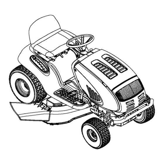
SECTION 4: KNOW YOUR LAWNTRACTOR NOTE: Steering Wheel not shown for clarity. Figure 3 Cruise ControI Button PTO (Power Take-off) Knob Choke Control Ignition Switch Brake Pedal Parking Brake Button Shift Lever Drive Pedal DeckLift Lever Cup Holder Systems Indicator Monitor/Hour Meter Seat Adjustment Lever Throttle Control Lever NOTE:... - Page 10 ThrottleControl L ever IgnitionSwitch The throttle control lever is located on the right side of WARNING: Never leave running the tractor's dash panel. This lever controls the speed machine unattended. Always disengage PTO, of the engine. When set in a given position, the throttle move shift lever into neutral position, will maintain a uniform engine speed.
- Page 11 Electric PTO Systems IndicatorMonitor / HourMeter (Power T ake-off) K nob Your tractor is equipped with four indicator lights and an hour meter located on the left side of the dash panel. To engage the power to the See Figure 6. cutting deck or other (separately BaRery available) attachments, pull...
-
Page 12: Operating Your Lawn Tractor
CruiseControl B utton ParkingBrakeButton The cruise control button is To set the parking brake, fully _rjl_-_ k. J depress the brake pedal and push the parking brake button in. to the left of the ignition switch. located on the tractor dash panel Push the cruise control button Hold the button in while taking your foot off the brake pedal. - Page 13 DrivingTheTractor from the discharge opening of the cutting WARNING: Keep hands and feet away deck. WARNING: Avoid sudden starts, cessive speed and sudden stops. NOTE: The deck wheels are an anti-scalp feature of the deck and are not designed to support the weight of WARNING: Do not leave the seat of the the cutting deck.
- Page 14 • Watch forholes, r uts,bumps, r ocks, o rother hidden objects. U neven terrain couldoverturn the Front View Pull Out Push In machine. Tallgrasscanhideobstacles. • Avoid turnswhen driving ona slope.Ifa turnmust bemade, t urndown theslope. T urning upa slope greatly increases t hechance ofa rollover. •...
-
Page 15: Making Adjustments
• Keep the blades sharp and replace the blades Operating TheHeadlights when worn. Refer to Cutting Blades on page 21 of this To turn the tractor's headlights on: manual for proper blade sharpening instructions. • Start the engine following the instructions earlier in this section. - Page 16 Steering Adjustment Leveling the Deck If the tractor turns tighter in one direction than the other, NOTE: Check the tractor's tire pressure before or if the ball joints are being replaced due to damage or performing any deck leveling adjustments. Refer to wear, the steering drag links may need to be adjusted.
-
Page 17: Maintaining Your Lawn Tractor
Nuts Lock Stabilizer Bracket Deck Adjustment Gear FRONT TO REAR SIDE TO SIDE Hex Cap Screw Figure 11 SECTION 7: MAINTAINING YOUR LAWNTRACTOR • Service the oil filter (if so equipped) as instructed WARNING: Before performing in the separate Briggs & Stratton Operator/Owner maintenance repairs, disengage... -
Page 18: Service
Lubrication Air Cleaner Service the pre-cleaner, if so equipped, and cartridge/ WARNING: air cleaner element as instructed in the Briggs & Before lubricating, repairing, or Stratton Operator/Owner Manual (or Kohlerengine's inspecting, always disengage PTO, move Owner's Manual) packed with your unit. shift lever into neutral position, set parking brake, stop engine and remove key to prevent... - Page 19 • Gently slidethecutting decktoward thefrontofthe To change or replace the deck belts on your tractor, tractor a llowing thehooks onthedeckto release proceed as follows: themselves fromthedeckstabilizer rod. • Lower the deck by moving the deck lift lever into the • Gently slidethecutting deck(from theright s ide) bottom notch on the right fender.
- Page 20 Battery Tray Drive belt (Lower) Variable-speed Shift Lever Opening Rear Idler Pulley Drive belt (Upper) Engine Pulley Transmission Transmission Pulley Front of Tractor NOTE: View shown from above tractor. Figure 15 • After disconnecting the battery cables, remove the • Remove the upper drive belt by pulling it up through battery and battery tray from beneath the seat.
- Page 21 • Slide thebeltoffofthevariable-speed pulley asyou Idler Adj. Rod liftthepulley upandoutthrough thebattery tray opening. • Remove t herearidlerpulley fromthedouble- i dler bracket w hileunrouting t hebeltfromaround both Neutral__ ///_Z _Return i._l/i _ Wrej__i Place ncheS Herl therearandthefrontidlerpulley. R efer t oFigure •...
- Page 22 The blades may be removed as follows. It is important that each cutting blade edge be ground equally to maintain proper blade balance. A poorly • Remove the deck from beneath the tractor, (refer to balanced blade will cause excessive vibration and may Catting DeckRemoval on page 18) then gently flip the cause damage to the tractor and result in personal deck over to expose its underside.
-
Page 23: Off-Season Storage
Fuses One can be found under the hood mounted behind the top of the dash panel on the support bar. The other can Two fuses are installed in your tractor's wiring harness be found under the seat mounted to the inside of the to protect the tractor's electrical system from damage tractor frame next to the battery tray. -
Page 24: Troubleshooting
SECTION 11: TROUBLESHOOTING Trouble Corrective Action Possible Cause(s) Engine fails to start PTO knob engaged. Place PTO knob in disengaged (OFF) position. Parking brake not engaged. Engage parking brake. Spark plug wire(s) disconnected. Connect wire(s) to spark plug. Throttle control lever not in correct Place throttle lever to FAST position. -
Page 25: Models J609H And Y609H Parts List
SECTION 12: MODELS J609H& Y609HPARTS LIST (forchoke) NOTE: Engine accessory parts are appficable to both model J609H and Y609H except where otherwise noted. PART REF. PART DESCRIPTION DESCRIPTION 710-0227 Self-tapping Screw, #8-18 x .5 751-0651 LH Exhaust Pipe (Model J609H) 710-0599 Oil Drain Valve Self-tapping Screw, 1/4-20 x.5... - Page 26 ModelsJ609H & Y609H "8 >...
- Page 27 Models J609H& Y609H REP. PART DESCRIPTION 783-1346 Grill Support Bracket (9-style) 710-0599 Self-tapping Screw, 1/4-20 x .5 710-0528 Hex Cap Screw, 5/16-18 x 1.25 710-0924 Phillips Pan Screw, 1/4-20 x .75 710-1017 Truss Phillips Screw, 1/4-20 x .625 725-1741 Ignition Switch 726-0272 Clamp, 9/16 710-0642...
- Page 28 ModelsJ609H & Y609H...
- Page 29 ModelsJ609H& Y609H REF. PART DESCRIPTION 747-1130A Deck Stabilizer Rod 683-0197 Lift Shaft Assembly 711-0332 Clevis Pin, .5 x .78 712-0206 Hex Nut, 1/2-13 712-0431 Flange Lock Nut, 3/8-16 712-3004A Flange Lock Nut, 5/16-18 712-3083 Hex Nut, 1/2-13 714-0104 Internal Cotter Pin 714-0145 Internal Cotter Pin 716-0106...
- Page 30 ModelsJ609H & Y609H...
- Page 31 Models J609H& Y609H REP. PART DESCRIPTION 683-0304 Lower Frame Assembly 710-0604A Self4apping Screw, 16-18 x .625 783-0726A RH Pivot Support Bracket 783-0727 LH Pivot Support Bracket 783-0728 Pivot Bar Bracket 710-0614 Hex Cap Screw, 3/8-16 x 1 (Grade 5) 711-1408 RH Drag Link 711-1409A LH Drag Link...
- Page 32 ModelsJ609H & Y609H "13 21 " >...
- Page 33 ModelsJ609H & Y609H PART REF. PART DESCRIPTION DESCRIPTION 783-1015 754-0468 Shift Lever Support Upper Drive Belt 17840 756-0981A Transaxle Mounting Bracket Flat Idler, 2.75 OD 618-0551 783-1016B Single-speed Transmission Assembly Speed Control Rod Bracket 631-0009A Shifter Knob 783-0667B Transmission Torque Bracket Shift Lever 647-0045 783-0669...
- Page 34 ModelsJ609H & Y609H...
- Page 35 Models J609H& Y609H PART DESCRIPTION 716-0231 E-ring, .75 721-0338 Seal, .75 x 1.0 x. 125 711-1431 Drive Shaft 741-0340 Sleeve Bearing, .75 x .1.0 x 1.0 736-0495 Thrust Washer, 1.0 x .632 x .0 42-tooth Bevel Gear 717-1362 717-1363 42-tooth Bevel Gear 750-1234 Spacer, .633 x 1.0 x .513 718-0228...
- Page 36 ModelsJ609H & Y609H _,_ 32...
- Page 37 ModelsJ609H & Y609H REP. PART DESCRIPTION 783-0653D Steering Support Bracket 754-0474 PTO Belt 717-1708 Electric PTO Clutch 783-1003 Electric Clutch Anti-rotation Bracket 710-0859 Hex Cap Screw, 3/8-16 x 2.5 710-1238 Hex Head Washer Screw, 5/16-18 x .875 712-0431 Flange Lock Nut, 3/8-16 732-0978 Extension Spring, .62 x 5.62 712-3004A...
- Page 38 ModelsJ609H & Y609H ® 3o_.._...
- Page 39 ModelsJ609H& Y609H PART DESCRIPTION 16606 Retainer Hook 17982 Spindle Reinforcement Plate 618-0240A Spindle Assembly, 5.0 Dia. 756-1187 Pulley Only 618-0241 Double Pulley Spindle Assembly 756-0603 Pulley Only 683-0254 Deck Adjustment Bracket w/Weld 683-0265C 46-inch Deck Shell 710-0167 Carriage Screw, 1/4-20 x .50 710-0344 Hex Cap Screw, 3/8-16 x 1.5 710-0501...
- Page 40 MANUFACTURER'S LIMITED WARRANTY FOR: OTRO_ R_ILT'_ c. Routine maintenance items such as lubricants, filters, The limited warranty set forth below is given by MTD blade sharpening and tune-ups, or adjustments such PRODUCTS INC ("MTD") with respect to new merchandise as brake adjustments, clutch adjustments or deck purchased and used in the United States, its possessions...
Need help?
Do you have a question about the J609H and is the answer not in the manual?
Questions and answers