Advertisement
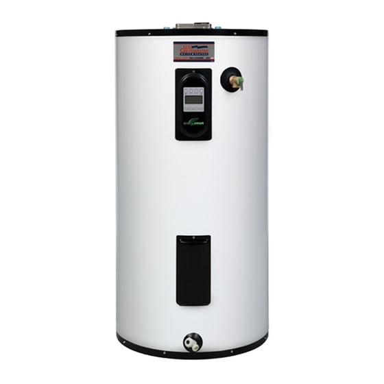
Residential
Electric
Water Heater
Installation
Instructions
and
Use & Care Guide
To obtain technical, warranty or service assistance during or
after the installation of this water heater, call toll free 1-800-
999-9515
When calling for assistance, please have the following
information ready:
1.
Model number
2.
7 Digit product number
3.
Serial number
4.
Date of installation
5.
Place of Purchase
Table Of Contents
PAGE
.....................................................................
2
Installing Your Electric Water Heater
........................................
3-8
Unpacking Instructions
................................................
3
................................................
4
...............................................
5
...................................................
6
....................................................
8
.......................................................
9-11
....................................
9
.....................................................
10
........................................................
1 1
Maintenance of Your Water Heater
.................................................
12-13
.............................................................
14
.............................................................
15
Thermostat Wiring Chart and Diagram
.....................................
16
6510236
October 2001
Supercedes 6510159
Advertisement
Table of Contents

Summary of Contents for US CRAFTMASTER ES2J40RD045V
-
Page 1: Table Of Contents
Residential Electric Water Heater Installation Instructions Use & Care Guide To obtain technical, warranty or service assistance during or after the installation of this water heater, call toll free 1-800- 999-9515 When calling for assistance, please have the following information ready: Model number 7 Digit product number Serial number... - Page 2 Your safety and the safety of others are very important. We have provided many important safety messages in this manual and on your appliance. Always read and obey all safety messages. This symbol alerts you to potential hazards that can kill or hurt you and others. All safety messages will follow the safety alert symbol and either the word "DANGER"...
- Page 3 INSTALLING YOUR Consumer Information Unpacking the Water Heater This water heater should be installed in accordance with the local code authority having jurisdiction, the power company or electric utility, and this installation manual. In the absence of local code requirements, follow the Excessive Weight Hazard...
-
Page 4: Water Heater Safety
Note: The water heater shall be located so it is not subject Location Requirements to physical damage by moving vehicles or area flooding. Site location FIGURE 1 RESIDENTIAL GARAGE INSTALLATION Select a location near the center of the water piping system. -
Page 5: Electrical Requirements
FIGURE 2 Electrical Requirements HEATING ELEMENT Electrical Shock Hazard Disconnect power before servicing. Replace all parts and panels before operating. Failure to do so can result in Notice: Applying electrical power to elements that are not submerged in water will destroy them. The manufacturer death or electrical shock. -
Page 6: Water System Piping
FIGURE 6 Water System Piping WATER PIPING INSTALLATION IN A CLOSED SYSTEM USE EITHER: THERMAL EXPANSION TANK Piping Installation PRESSURE RELIEF VALVE PRESSURE REDUCING Piping, fittings, and valves should be installed according VALVE WITH BYPASS to the installation drawing (Figure 6). If the indoor HOT WATER OUTLET installation area is subject to freezing temperatures, the... - Page 7 Please note the following: Temperature and Pressure Relief Valve DO NOT install this water heater with iron piping. The system should be installed only with new piping that is suitable for potable (drinkable) water such as copper, CPVC, or polybutylene. DO NOT use PVC water piping.
-
Page 8: Installation Checklist
Important:Onlya newtemperature andpressure r elief Installation Check List valveshould beused withyourwaterheater. D onotuse anoldor existing valveas itmaybedamaged or not Water Heater Location adequate fortheworking pressure ofthenewwater heater. D onotplace anyvalvebetween thereliefvalve andthetank. • Centrally located with the water piping system. •... -
Page 9: Operating Your Water Heater
OPERATING YOUR WATER HEATER Water Temperature Before operating the water heater, perform the following: Regulation 1. Make sure the water heater has been properly installed. Completely fill the tank with water. (See Figure 2) 3. Apply power to the water heater only after the tank is completely filled with water. -
Page 10: Adjusting The Thermostat
Adjusting the Thermostat/High Limit Control This water heater is equipped with one or more adjustable temperature regulating thermostats and a manual reset high limit control. The following procedures must be performed when changing the temperature of the stored water or resetting the high limit control. Upper and lower thermostats must be adjusted to the same temperature. -
Page 11: Operational Conditions
Operation Conditions Maintenance Anode Rod/Water Odor Each water heater contains at least one anode rod, which Temperature and Pressure will slowly deplete while protecting the glass-lined tank Relief Valve from corrosion and prolonging the life of the water heater. Certain water conditions will cause a reaction between this rod and the water. - Page 12 Draining and Flushing Heating Element Replacement The water heater should be drained if being shut down during freezing temperatures. It is recommended that the tank be drained, and flushed every 6 months to remove sediment which may buildup during operation. To drain the tank perform the following steps: Electrical Shock Hazard...
-
Page 13: Trouble Shooting Chart
9. Connect the electric wires to the heater element. FIGURE 14 THERMOSTAT Make sure the wires are secure. Replace the plastic thermostat cover making sure the attachment points are engaged on the thermostat. SCREW-IN 10. Replace the access cover(s). ELEMENT 11. -
Page 14: Repair Parts Illustration
REPAIR PARTS ILLUSTRATION ALTERNATE T&P TOP WATER LOCATION CONNECTIONS ...__.® ..-@ TABLE TOP MODEL ® .© ®... - Page 15 REPAIR PARTS ILLUSTRATION SIDE WATER CONNECTIONS PARTS DESCRIPTION REPAIR PARTS ITEM ACCESS DOORS Repair parts may be ordered through your plumber, local THERMOSTAT COVERS (UPPER & LOWER) distributor, home improvement center, or by calling 1- UPPER THERMOSTAT • 800-999-9515. When ordering repair parts always give LOWER THERMOSTAT •...
- Page 16 THERMOSTAT WIRING DIAGRAM FUSED DISCONNECT FUSED DISCONNECT CIRCUIT BREAKER FUSED DISCONNECT CIRCUIT BREAKER CIRCUIT BREAKER FUSED DISCONNECT OR CIRCUIT BREAKER FUSED DISCONNECT o.,_ ..... CIRCUIT BREAKER ,,'_- NEUTRAL ....-, ___ WlTHH_?THLLMIT BLACK >- UPPER THERMOSTAT BLUE WITH HIGH LIMIT CONTROL IYELL...


Need help?
Do you have a question about the ES2J40RD045V and is the answer not in the manual?
Questions and answers