Yard Machines 580 Series Operator's Manual
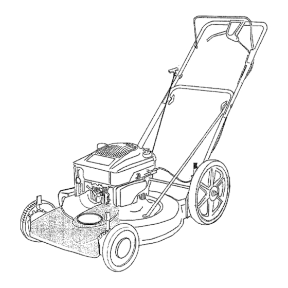
22" side discharge high wheel lawn mower
Hide thumbs
Also See for 580 Series:
- Operator's manual (29 pages) ,
- Operator's manual (16 pages) ,
- Operator's manual (20 pages)
Advertisement
Quick Links
Download this manual
See also:
Operator's Manual
®
OPERATOR'S
MANUAL
22" Side Discharge
High Wheel
Lawn Mower
Model Series 580
IMPORTANT:
READ SAFETY
RULES AND INSTRUCTIONS
CAREFULLY
Warning:
This unit is equipped with an internal combustion engine and should not be used on or near any unimproved
forest-
covered, brush-covered
or grass-covered
land unless the engine's exhaust system is equipped witha spark arrester meeting
applicable local or state laws (if any). If a spark arrester is used, it should be maintained
in effective workir_g order by the operator.
In the State of California the above is required by law (Section 4442 o_the California Public Resources Code). Other states may have
similar laws_ Federal laws apply on federal lands, A spark arrester for the muffler is available through your nearest engine authorized
service dealer or contact the service department,
P.O. Box 368022 Cleveland, Ohio 44136-9722.
MTD PRODUCTS
INC. P.O. BOX 368022 CLEVELAND,
OHIO 44136-9722
PRINTED IN U.S.A.
FORM NO. 770-10113
(10/98)
Advertisement

Subscribe to Our Youtube Channel
Related Manuals for Yard Machines 580 Series


Summary of Contents for Yard Machines 580 Series
- Page 1 ® OPERATOR'S MANUAL 22" Side Discharge High Wheel Lawn Mower Model Series 580 IMPORTANT: READ SAFETY RULES AND INSTRUCTIONS CAREFULLY Warning: This unit is equipped with an internal combustion engine and should not be used on or near any unimproved forest- covered, brush-covered or grass-covered...
-
Page 2: Calling Customer Support
SECTION 1: FINDING LAWN MOWER MODEL NUMBER This Operator's Manual is an important part of your new lawn mower. It will help you assemble, prepare and maintain your mower properly. Please read and understand what it says. Before you start to prepare your equipment for its first usel please locate the model plate and copy the information from it in the space provided below. - Page 3 SECTION 3: IMPORTANT SAFE OPERATION PRACTICES & WARNING: This symbol points out important safety instructions which, if not followed, could endanger the personal safety and/or property of yourself and others. Read and follow all instructions in this manual before attempting to operate your lawn mower. Failure to comply with these instruct{ass may result in personal injury.
- Page 4 Do not: serious personal injury. Keep a firm hold on the handle and walk, never run. If you feel you are • Do near drop-offs, ditches losing your footing, RELEASE BLADE embankments. The operator could lose footing or CONTROL HANDLE IMMEDIATELY and the blade balance.
- Page 5 stopped. Disconnect thespark plug wire, a ndkeep Grass catcher components are subject to wear. me wireawayfromthe spark#lugto prevent damage deterioration, which could expose accidental starting. moving parts or allow objects to be thrown. safety protection, frequently check components • Check the blade and engine mounting bolts a_...
- Page 6 USE THIS PAGE AS A GUIDE TO DETERMINE SLOPES WHERE YOU MAY NOT OPERATE SAFELY. '.., SIGHT AND HOLD THIS LEVEL WITH A VERTICAL TREE A POWERPOLE WARNING Do not mow on inclines with a slope in excess of 15 degrees (a rise of approximately 2-1/2 feet every 10 feet).
- Page 7 SECTION 5: CONTENTS OF HARDWARE PACK For identification purposes, lay out the hardware according to the illustration below. Part numbers are shown in parentheses CHardware pack may contain extra items which are not used on your unit. ) Attaching the struts Hex Bolt 1/4-20:.620 (710-0751 )
-
Page 8: Section 7: Set-Up Instructions
SECTION 6: UNPACKING Removing Unit from Carton • Remove staples, break glue on top flaps, or cut tape at carton end and _eel along top flap to open carton. Remove loose parts if included with unit (i.e., operators manual, etc.). See Figure 3. Figure 3 •... - Page 9 Assembling Handle Lift lower handle 2. Lift uppel handle Figure 5 Raise the lower handle in the direction shown in Figure 5 (step 1) till it snaps into place. Raise the upper handle in the direction shown in Figure 5 (step 2). Tighten the hand knobs which are already on the handle.
- Page 10 Attach theotherendofthestrutsasfollows. P lace onecupped washer o vereachhexboltaligning the crowned sideofthewasher against the head ofthe bolt.Insert h exboltsupthrough the middle holesin deckbeside theengine andthenthrough thestruts, S ecure withcupped washers (cupped sideagainst strut)andhexnuts.SeeFigure 7. Carriage Bolt Saddle Washer Cupped Washer Installing Rear Wheels and Axle Shaft NOTE: Some lawn mower models covered in this operator's manual are shipped with the rear wheels and axle shaft already installed on the unit.
- Page 11 • Install the other wheel assembly and the other end of the axle shaft in the same way. • Remove the blocks from the rear of the mower ana place the rear height adjusters in the same relative position as the two front height adjusters. Attaching Starter Rope...
- Page 12 • Pushthehooks ontopofthebaffletillthesesnapoverthe hingeonthe discharge c hute. R elease the chutedeflector. Chute Deflector Mulching Baffle Hook Figure 11 SECTION 8: CONTROLS IMPORTANT: Always wear safety glasses while operating the mower, or while performing any adjustments or repairs on it. Read this operator's manual and safety rules before operating your lawn mower. Compare the illustrations in Figure 12 with your lawn mower to familiarize yourself with the location of various controls and adjustments, Blade Control Handle...
-
Page 13: Section 9: Operation
Drive Clutch Control Squeeze the drive clutch control against the upper handle of the mower to engage the drive mechanism and move the wheels. Release the drive clutch control to slow down the mower when negotiating an obstacle, making a turn, or stopping the mower. Recoil Starter The recoil starter rope is attached to the handle. - Page 14 Before Starting • Attach spark plug wire to spark plug. If your unit is equipped with a rubber boot over the end of the spark plug wire, make certain the metal cap on the end ef the spark plug wire (inside the rubber boot) is fastened securely over the metal tip on the spark plug.
- Page 15 • Squeeze the drive clutch control against the upper handle of the mower to engage the drive mechanism and move the wheels. Release the drive clutch control to slow down the mower when negotiating an obstacle, making a turn. or stopping the mower. WARNING: If you strike a foreign object, stop the engine.
- Page 16 Turn the lower handle around so the notch on the bottom of the lower handle is facing forward as shown in Figure 14B. Reassemble, placing the bottom holes in the handle over the weld pins in the handle mounting bracket. Reassemble the upper handle to the lower handle.
- Page 17 To adjust the drive clutch, rotate the adjustment wheel with your fingers. You should rotate the wheel clockwise to tighten the cable and counter-clockwise to loosen the cable. See Figure 16. If the drive clutch control handle is not in a comfortable position for you, adjust the handle by tightening the adjustment wheel.
-
Page 18: Section 12: Maintenance
Lubricate pivot point ILUbtors_ Lubricate jaxle bolt, inner surface Lubricate of wheel pivot point Figure 17 SECTION 12: MAINTENANCE work or adjustments on your lawn mower. WARNING: Always stop engine and disconnect spark plug wire before performing any maintenance Cleaning Mower The underside of the mower deck should be cleaned after each use to prevent any build-up of grass clippings, leaves, dirt, or other debris. - Page 19 To Remove Blade Remove the Dolt and the bell washer securing the blade assembly to the crankshaft. See Figure 18A. Remove the two pairs of hex bolt and lock nut holding the blade to the blade adapter and the pulley assembly.
- Page 20 Replacing Rear Flap The rear flap is attached to the back of the mower deck, and is designed to minimize the possibility of objects being thrown from the rear of the mower towards the operator. If the rear flap is damaged, replace as follows. •...
- Page 21 Lift and stabilize the front of the deck. • Loosen the center hex bolt and lower the blade and engine pulley until there is adequate clearance to move the belt past the belt keeper. Remove the belt from the engine pulley and around the blade. See Figure 21. Reassemble in reverse order with new belt (part # 754-0465), NOTE: Begin idler reassembly by inserting bolt up through the idler bracket hole.
- Page 22 SECTION 14: TROUBLE SHOOTING GUIDE Trouble Corrective Actions Possible Cause(s) Engine fails to Blade control handle disengaged. Engage blade control handle, start Spark plug wire disconnected. Connect wire to spark plug. Dirty airoleaner. Refer to the engine manual packed with your unit, Primer button not depressed.
-
Page 23: Repair Parts
SECTION 15: REPAIR PARTS SEE ENGINE MANUAL... - Page 24 Ref. Ref. PaN No. PaN No. Description Description 742-0642 Blade 22" 731-1057 Upper Drive Cover 742-0742 Mulching Blade - 22" 731-0620 Drive Lever 736-0452 Bell Washer .396 I.D. x 1.140 O.D. x Lower Drive Cover 731-1 O58 Hex Screw 1/4-20 x 1.50 710-0606 731-1059 Mounting Cap...
- Page 25 Self-Propelled Front Wheel Drive Transmission: 618-0298A • IMPORTANT: For the proper working of your mower, use Factory Approved Parts. V-BELTS are specially designed to engage and disengage safely. A substitute (non-OEM) V-Belt can be dangerous if it fails to disengage comletely.
- Page 26 Engine Shroud Chart NOTE: This chart shows all the optional engine shrouds for the lawn mowers covered in this manual. To order replace- ment parts, please refer to the shroud and hardware applicable to your lawn mower unit. !Part No: !Color Part No.
- Page 27 MANUFACTURER'S LIMITED WARRANTY FOR: YARD MACHINES For TWO YEARS from the date of retail purchase products sold or exported outside of the United within the United States of America, its possessions States of America, its possessions and territories, and territories,...
Need help?
Do you have a question about the 580 Series and is the answer not in the manual?
Questions and answers