Table of Contents
Advertisement
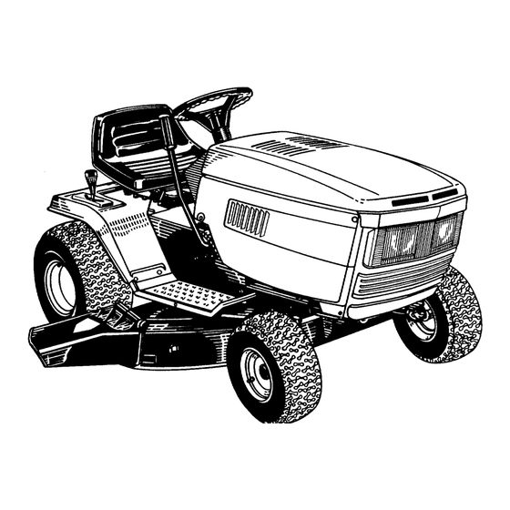
42"
and
46"
Lawn
Tractors
Operating
Manual
Model
Nos.
TMO-3310001
TMO-3410002
TMO-3510003
(Model TM0-3510003
Shown)
WARNING:
This
unit is equipped
with an internal
combustion
engine
and should
not be used on or near any
unimproved
forest-covered,
brush-covered
or grass-covered
land unless the engine's
exhaust system is equipped with a
spark arrester meeting applicable local or state laws (if any). If a spark arrester is used, it should be maintained in effective
working order by the operator.
In the State of California the above is required by law (Section 4442 of the California Public Resources Code). Other states
may have similar laws. Federal laws apply on federal lands. A spark arrester for the muffler is available through your nearest
engine authorized service dealer or contact the service department, P.O. Box 368022, Cleveland, Ohio 44136-9722.
Advertisement
Table of Contents
Troubleshooting

Subscribe to Our Youtube Channel
Related Manuals for MTD TMO-3410002


Summary of Contents for MTD TMO-3410002
- Page 1 42" 46" Lawn Tractors Operating Manual Model Nos. TMO-3310001 TMO-3410002 TMO-3510003 (Model TM0-3510003 Shown) WARNING: This unit is equipped with an internal combustion engine and should not be used on or near any unimproved forest-covered, brush-covered or grass-covered land unless the engine's exhaust system is equipped with a spark arrester meeting applicable local or state laws (if any).
-
Page 2: Safe Operation Practices
IMPORTANT SAFEOPERATION PRACTICES AL SAFETY AND/OR PROPERTY OF YOUR_ELF AND OTHERS. READ AND FOLLOW ALL INSTRUCTIONS IN THIS MANUAL THIS SYMBOL POINTS OUT IMPORTANTSAF-TY INSTRUCTIONSWHICH, IF NOT FOLLOWED,COULDENDANGERTHE PERSON- BEFORE ATTEMPTINGTO OPERATEYOUR UI_IT. WHENYOU SEETHIS SYMBOL-- Z_, HEEDITS WARNING. Your lawn mower was bt lit to be operated accordingto the rules for safe operation in this manual. As with any type of power el uipment, carelessnessor error on the part of the operator can result in injury. - Page 3 1. Keep children outofthe mowing area a nd inwatchful care of 5. Check the blade and engine mounting bolts at frequent anadult other than the operator. intervals for proper tightness. Also, visually inspect blade for 2. Be alert and turn machine offifchildren enter the area.
-
Page 4: Battery Information
ASSEMI:|LY INSTRUCTIONS BATTERY INFORMATION IMPORTANT: After assembly, service engine with gasoline, and check oil level as instructed in the separate engine manual packed with WARNING your unit. care as A. Battery acid must be handled with great NOTE: Reference to right or left hand side of the contact with it can burn and blister the skin. -
Page 5: Attaching Thesteering Wheel
ATTACHING THESTEERING WHEEL Steering Wheel 1. The hardware for attaching the steering wheel has been packed inside the steering wheel. Hex Lock Carefully pry off the steering wheel cap and Bolt remove the hardware. Remove the steering bellow from the lift lever on Cupped the right hand side of lawn tractor. -
Page 6: Leveling The Deck
LEVELING THE DECK DeckHanger -___ Channel. With unit on hard, level surface, measure the distance from the bottom edge of the center of the left side of deck to the ground. Measure the same distance us1 able/ the center of the right side of the deck, just behind the Lift Link/ chute area. -
Page 7: Clutch-Brake P Edal
CONTROLS IGNITION SWITCH HYDROSTATIC CONTROL LEVER The ignition switch is located on the dashboard. The The hydrostatic control lever is located on top of the engine is started by turning the key to the START fender on the right side of the tractor. This single con- position. -
Page 8: Operation
RELIEFVALVE OPERATION i init can A hydrostatic relief valve is provided so the r which be moved without the engine running. The lev{ onsole. operates the relief valve is located on the c See figure 9. WARNING tic con- To operate the relief valve, place the hydrost_ AVOID SERIOUS INJURY OR DEATH 3, push trol lever in neutral, release the parking brak... -
Page 9: Seat Adjustment
1. Place the lift lever in the BLADES OFF position. & WARNING: Before leaving the operator's 2. Depress the clutch-brake pedal and set the park- position for any reason, disengage ing brake. blades, place the hydrostatic control lever in neutral, engage the parking brake, shut 3. -
Page 10: Brake Adjustment
CUTTING DECKENGAGEMENT ADJUSTMENT Speed Selecl orl The cutting deck engagement may be adjusted Adjusting R__d make certain deck is disengaged when lift lever is in the BLADES OFF position, or to obtain more drive in the cutting positions. Correct adjustment as follows. With the engine off, place the lift lever in the highest cutting position (first position). - Page 11 LUBRICATION WARNING: Always stop engine and dis- connect spark plug wire before cleaning, lubricating or doing any kind of work on lawn tractor. STEERING GEARS Lubricate teeth of steering gears with automotive multi-purpose grease after every 25 hours of opera- tion or once a season.
-
Page 12: Maintenance
To adjust the toe-in, follow these steps. MAINTENANCE 1. Remove the hex nut and lock washer, and drop the end of the tie rod from the axle bracket. See & WARNING: Disconnect the spar_( plug figure 16. wire and ground against €... - Page 13 CHARGING THE BATTERY 1. Remove the large bolt and lock washer which holds the blade and adapter to the blade spindle. The engine is equipped with an alternator which charges battery when tractor is operated. Under 2. Remove the blade and adapter from the spindle. normal conditions, the battery only needs to be...
-
Page 14: Beltremoval And Replacement
7. Disconnect the stabilizer plate from the stabilizer & WARNING: Excessive pressure (q)ver 30 shaft assembly by removing the hairpin clips and p.s.i.) when seating beads may cause flat washers and sliding out the rod. Refer to tire/rim assembly to burst with fol ce suf- figure 12. -
Page 15: Optional Equipment
Center Bolt OFF-SEASON STORAGE Lock Washer Flat Washer If the machine is to be inoperative for a period longer than 30 days, prepare for storage as follows. 1. Clean the engine and the entire unit thoroughly. 2. Lubricate all lubrication points. -
Page 16: Troubleshooting Guide
TROUBLE SHOOTING GUIDE PROBLEM POSSIBLE CAUSE(S) CORRECTIVE ACTION Engine will not Safety switch button There are tw( switches in the starting circuit of your unit: the clutch pedal switch and the deck lift lever crank, not depressed switch. Make ;ertain the actuator is fully depressing the buttons on each switch. Battery installed The battery rt Jst be installed with negative terminal attached to black ground wire. - Page 17 only to ensure performance of your product is to use original equipment parts accessories. When you substitute, you take a chance on quality, reliability, safety and performance. 746-O634 Throttle Control Wire 35" Lg. Cold Crank Am 725-1707 731-0484A Front Hub Cap (Black) Front Wheel Bearinc 741-0487A Fuse 7.5 AMP...
-
Page 18: Slope Gauge
SLOPEGAUGE... - Page 19 Normal wear parts are defined as 5. The provisions as set forth in this warranty batteries*, belts, blades, blade adapters, grass bags, provide the sole and exclusive remedy of MTD 4[,..) dl,_'_ rider deck wheels, seats, snow thrower skid shoes, PRODUCTS...
- Page 20 SER /ICE NATIONWIDE HOW TO OBTAIN REPLACE _ENT PARTS AND SERVICE The merchandise _ 3u have purchased from us has been carefully engineered and m _nufactured under rigid quality standards and should give you s_ tisfactory and dependable operation. However, like all mechanical nerchandise, it may occasionally...
Need help?
Do you have a question about the TMO-3410002 and is the answer not in the manual?
Questions and answers