LG WM2501H Series Service Manual
Hide thumbs
Also See for WM2501H Series:
- User manual (108 pages) ,
- Service manual (64 pages) ,
- Specifications (2 pages)

Related Manuals for LG WM2501H Series


Summary of Contents for LG WM2501H Series
- Page 1 Website: http://www.LGEservice.com E-mail: http://www. LG Eservice.com/techsup. html MACHINE WASHING RVlC ,&, CAUTION READ THiS MANUAL CAREFULLY TO DIAGNOSE PROBLEMS CORRECTLY BEFORE SERViCiNG THE UNIT, MODEL: WM2501H*A...
-
Page 2: Table Of Contents
CONTENTS 1. SPECIFICATIONS ....................... 2. FEATURES AND TECHNICAL EXPLANATION ..............3. PARTS IDENTIFICATION ....................4. INSTALLATION AND TEST ....................5. OPERATION ........................5-1. CONTROL PANEL FEATURES ................. 5-2. CYCLE GUIDE ......................5-3. SPECIAL FUNCTIONS ....................5-4. EXPLANATION OF EACH PROCESS ............... -
Page 3: Specifications
1. SPECIFICATIONS ITEM WM2501H*A COLOR W:BLUE WHITE, V:STAINLESS SILVER, R:CANDY APPLE RED POWER SUPPLY AC 120 V, 60 Hz PRODUCT WEIGHT 192 Ibs (87kg) WASHING 280 W ELECTRIC POWER DRAIN MOTOR 80 W CONSUMTION WASH HEATER 1000 W WASH 46 rpm REVOLUTION SPEED SPIN 0-1200 rpm... - Page 4 2. FEATURES & TECHNICAL EXPLANATION 2-1. FEATURES Ultra Capacity The Larger drum enables not just higher head drop stronger centrifugal force, also less tangling wrinkling of the laundry. Heavier loads, such as king size comforters, blankets, and curtains, can be washed. Direct Drive System...
- Page 5 2-2. NEURO FUZZY WASHING TIME OPTIMIZATION To get the best washing performance, optimal time is determined by the water temperature, the selected washing temperature, and the size of the load. washing time the best NEURO- washing rinsing time FUZZY performance spin rhythm, time EFFECT 2-3.
- Page 6 2-5. THE DOOR CAN NOT BE OPENED ® While program is operating. ® When a power failed and power plug is taken out in operation. While Door Lock lights turn on. ® While the motor is in the process of intertial rotating, through the operation is paused. •...
-
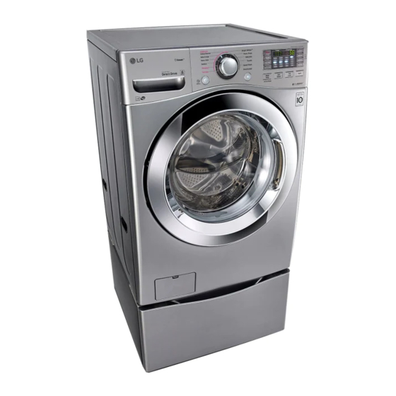
Page 7: Parts Identification
3. PARTS IDENTIFICATION Shipping Bolts Power Plug • If the supply cord is damaged, it must be replaced by the manufacturer or its authorized service technician in order to avoid a hazard. Panel Drain Hose- Drum Light Dispenser ---Drum Cold Water Inlet .Door Seal Door Hot Water Inlet... -
Page 8: Installation And Test
4. INSTALLATION & TEST Ii1 Before servicing, ask the customer what the trouble is. Check the setup (power supply is 120V, remove the transit bolts, level the washer...) I-J] Check with the troubleshooting guide. Plan your service method by referring to the disassembly instructions. - Page 9 HOW TO CONNECT THE INLET HOSE • Verify that the rubber washer is inside of the valve connector. • Tighten the inlet hose securely to prevent leaks. • CONNECT THE DRAIN HOSE Make sure that the hose is not twisted. Avoid submerging the end of the hose.
- Page 10 _TEST OPERATION Press the POWER button. Press the Start/Pause button. • Connect the power plug to • Listen for a click to determine if the outlet. the door has locked. • Connect the inlet hose. Check the water supply. heck the water heating Check the automatic function.
-
Page 11: Operation
5. OPERATION 5-1. CONTROL PANEL FEATURES II WM2501H*A... - Page 12 • Delay Wash allows the start of any cycle to be delayed for 1_-19 hours. , This display shows: • STEAM: Use the STEAM button to add steam to the cycle for the a) the estimated time remaining extra cleaning. in the cycle when operation.
-
Page 13: Cycle G Uide
5-2. CYCLE G UIDE The cycle guide below shows the options and recommended fabric types for each cycle. Dressshirts, blouses ExtraHot/Cold High(=) Normal Heavilysoiled ExtraHigh(_) Heavy underwear,work SANITARY NoSpin(o) Light clothes,diapers,etc. Low (---) Medium(--) Warm/Cold Low (---) Normal Largeitems such as BULKY/ Medium(--) Heavy... -
Page 14: Special Functions
5-3. SPECIAL FUNCTIONS The option buttons also activate special functions, including CHILD LOCK, LOAD SIZE, TUB CLEAN, and SPIN SENSE. Press and hold the option button marked with the special function for 3 seconds to activate. CHILD LOCK Use this option to prevent unwanted use of the washer or to keep cycle settings from being changed while the washer is operating. -
Page 15: Explanation
5-4. EXPLANATION OF EACH PROCESS Process Explanation Stay • Electrical power is supplied • Washer is ready to work and the micom is in the active mode. Water After loading laundry and selecting a course and a cycle, water is •... - Page 16 Process Explanation Inte rm ittent • To reach the correct set speed, the motor rotates clockwise spin counterclockwise directions after spin process starts. If the water level frequency is lower than 23.0 kHz, a washer senses suds and starts suds removal process. Rinse •...
-
Page 17: Wiring Diagram/Program Chart
6. WIRING DIAGRAM/PROGRAM CHART i EF]ZVqH _'_ HSVM O_ NgZV3H__, rr" < _< Q,.,. >__ >__ >_ >_ _... - Page 18 Spin Drain ¢o <: < £ ©...
-
Page 19: Test Mode
7. TEST MODE 7-'1. SAFETY CAUTION II There's built-in AC 120V and DC power in output terminal of PWB assembly in common. Be careful electric shock when disconnecting parts while trouble shooting. (Wear Electro Static Discharge gloves when working.) II After cutting off the power when changing PWB assembly, disconnect or assemble. II Be careful static when handling PWB assembly, and use Electro Static Discharge plastic pack when delivering or keeping it. -
Page 20: Troubleshooting
8. TROUBLESHOOTING 8-1. SAFETY CAUTION • There's built-in AC 120V and DC power in output terminal of PWB assembly in common. Be careful electric shock when disconnecting parts while trouble shooting. (Wear Electro Static Discharge gloves when working.) • After cutting off the power when changing PWB assembly, disconnect or assemble. - Page 21 ERROR SYMPTOM CAUSE • The connector (3-pin, male, white) in the MOTOR HARNESS is not connected to the connector (3-pin, female, white) of STATOR ASSEMBLY. LOCKED • The electric contact between the connectors (3-pin, male, MOTOR white) in the MOTOR HARNESS and 4-pin, female, white ERROR connector in the MAIN PWB ASSEMBLY is bad or unstable.
-
Page 22: Troubleshooting Summary
8-3. TROUBLESHOOTING SUMMARY iiiil_!_ iliiii_i!ii!i_!i!!ii!iil _!_!!_!!_!i_i_!i_i_!i_!_i_i!i!_i_i_ii!ii!_i_i!_ii_ii_ii_ii_ii_ii_ii_i_!i_!i_!ii!ii!ii!ii!iiiii!ii!_i!ii!ii!ii!ii!ii!i_... -
Page 23: Troubleshooting
8-4. TROUBLESHOOTING WITH ERROR Replace the is the voltage of the inlet _--_\ I iNLET VALVE valve connector 120 V AC? ASSEMBLY. (Check the all terminal of INLET VALVE ASSEMBLY displayed? while the power is on.) Check the AiR When you press both CHAMBER STEAN button and and the tube... -
Page 24: Drain Error
displayed? is the coil of the drain Replace the Is the connector connected L-_I Reconnect or ] pump too high or low? DRAIN to pump motor assembly (resistance of the coil repair PUMP disconnected is 10-20_) ASSEMBLY. the connector.J disassembled? (Refer to 9-4 Pump motor assembly) Replace the... - Page 25 Reconnect Is the connector connected thermistor disconnected or Yes repair the connecto disassembled? displayed? Reconnect Is the connector connected repair to heater disconnected the connector disassembled? Steam generator thermistor Steam generator heater Wash thermistor Replace the is thermistor resistance THERMISTOR out of range? Wash heater ASSEMBLY...
- Page 26 - part of motor displayed? Reconnect Check the connectors below. [-_1 Motor the connector. Is the connector disconnected (con nector/ or disassembled? wire / motor) (motor hall sensor connector, Is rotor magnet cracked? motor drive connector) the ROTOR part of main PWB fe_I Replace assembly (RD4, NA1)
- Page 27 Replace the Is there clicking sound once '--_.\ displayed? or twice when the ASSEMBLY. START/PAUSE button is pressed to start the cycle? Is the connector connected to door switch or main PWB repair N[_oo Reconnect or the connector Replace the disconnected? Is DOOR SWITCH DOOR...
- Page 28 displayed? _!i_]ii]i_]i_i_!_!_!_!_i_!_!_!_!_j_ii!_i_!_i_i_i_i_!_!_!_!_ d i s play e d ? When you press both Put laundry Check the AiR Does the laundry lean STEAM button and evenly CHAMBER toward one side, not evenly Yes/) PRE-WASH button in the DRUM and the tube put in the DRUM assembly? r-q/[ simultaneously, is the...
- Page 29 displayed? Reconnect or Is the connector connected repair to pressure sensor the connector disconnected disassembled? Replace the Is the resistance of the pressure pressure sensor out of switch range? (pin 1~ pin 3) (21 ~23 £__+10%) Fix the air Is the AIR CHAMBER and chamber the tube clogged? and remove...
-
Page 30: Troubleshooting
8-5. TROUBLESHOOTING ELSE 1. Be careful of electric shock if disconnecting parts while troubleshooting. 2. First of all, check the connection of each electrical terminal with the wiring diagram. 3. If you replace the MAIN PWB ASSEMBLY, reinsert the connectors correctly. - Page 31 Is the connector connected Repair to Main PWB / Display the connector PWB disconnected or yeL_s Reconnect or disassembled? Replace the Is the display PCB broken? DISPLAY (check the buzzer sound and LED light while push ASSEMBLY the button.) Is the button of panel stuck? button Ye_s Repair the...
- Page 32 Remove the transit bolts Have all the transit bolts and base packing been removed? and Base packing. Move the washer or Is the washer installed on a solidly constructed floor? reinforce the floor. Check if the washer is perfectly level as follows: Base Packing Level Check the leveling of the washer with a Level...
- Page 33 Prewash Refer to Is water supplied? NO WATER SUPPLY Are receptacles correctly connected to the Check the wiring. terminals of the INLET VALVE ASSEMBLY? Main wash Steam Put the detergent in the correct place. Has detergent been put in the correct Pre wash Main wash compartment of the dispenser?
- Page 34 Prewash Refer to Is water supplied? NO WATER SUPPLY Are the plugs correctly connected to the terminals of Main wash the INLET VALVE ASSEMBLY? Checkthe wiring on the dispenser. Steam . Is liquid detergent/softener/bleach put in the correct Put it in the correct compartment.
-
Page 35: Component Testing
9. COMPONENT TESTING INFORMATION A WARNING When Resistance (Ohm) checking the Component, be sure to turn the power off, and do voltage discharge sufficiently. 9-1. FILTER ASSEMBLY (LINE FILTER) Wiring diagram MAIN ASSEMBLY Test points Result (1) (3) Test Points Result WH (1) to RD (3) WH (3) to RD (1) - Page 36 9-2. DOOR LOCK SWITCH ASSEMBLY Wiring diagram MAIN PWB MICOM --Do-- TTYJ ;©) Relay Relay Common terminal 3f Valve Door switch The Door Lock Switch Assembly consists of a Heating PTC, a Bimetal, Function a Protection PTC, and a Solenoid. It locks the door during a wash cycle.
- Page 37 Test points Result Test Points Result Remarks (2) to (4) 700-1500 At 77°F (25°C) (3) to (4) 60-90 _ At 77°F (25°C) (4) to (5) Infinity (2) to (4) 120 Vac Voltage Input...
-
Page 38: Stator Assembly
9-3. STATOR ASSEMBLY Wiring diagram MAIN PWB Function The DD motor can be driven from stopped to maximum speed in infinite steps either direction. There are 36 poles on the stator; 12 permanent magnets spaced around the rotor. There are no brushes to wear out. - Page 39 The hall sensor determines the speed and direction of the motor. It also can read that the load is off balance when the drum speed fluctuates. Test point Result (Hall Sensor)
- Page 40 7. To measure output signal voltage from the hall sensor, carefully move test leads to terminals 1 to 4, blue and gray. Slowly rotate motor rotor by hand. You should read a pulsing 10 Vdc. If 10 Vdc is measured from 1 to 4, move lead on blue wire to red wire, terminal 2.
-
Page 41: Pump Motor Assembly
9-4. PUMP MOTOR ASSEMBLY Wiring diagram __Cs CONNECTO_ Pump Driving circuit L ......_ ..I..J I.._____ DRAINPUMP CIRCULATIONPUMP * Each circuits of loads in wiring diagram are all same. Object For Drain For Circulation Function Two pump motors are used to drain the tub and to circulate the water / detergent solution. Drain Pump Circulation... -
Page 42: Inlet Valve Assembly
9-5. INLET VALVE ASSEMBLY Wiring diagram MICOM • i:Rsl I - -C_ , Inlet valve driving circuit CONNiCTORI --@-- MIAN PWB 11 : _ BL COMMON GY YI. (BK) _-%AIN_ _PRE-'_ ..^,,_.O'1"_ ", _WASHJ _VALVE _WAS _LI::/'_'_ LVEJ INLET VALVE * Each circuits of loads in wiring diagram are all same. -
Page 43: Heater Assembly
9-6. HEATER ASSEMBLY Wiring diagram MAIN PWB MICOM E_Ill /F_ac Tab Relay STEAM Heater driving circuit GENERATOR WASH L ....... HEATER HEATER * Each circuits of loads in wiring diagram are all same. Function 1. The Wash Heater is designed to raise the wash water to the desired temperature selection... -
Page 44: Thermistor
9-7. THERMISTOR ASSEMBLY Wiring diagram MAIN PWB ', WH---- '/VV' C _ - ,'''' _--_ MICOM '/V_ C ___ ''''' WASH THERMISTOR The thermistor (temperature sensor) is used to monitor water temperature in the tub Function or Steam Generator. Test Test Result Remarks... - Page 45 Result Wash Thermistor Test Points Result Remarks (tolerance _+5%) 39.5 k_ At 86°F (30°C) (1) to (2) 26.1 k_ At 104°F (40°C) 12.1 k_ At 140°F (60°C) 8.5 k_ At 158°F (70°C) 3.8 k_ At 203°F (95°C) 2.8 k_ At 221 °F (105°C) Steam generator Thermistor Test Points...
-
Page 46: Steam Generator
9-8. STEAM GENERATOR ASSEMBLY Wiring diagram ; MAIN PWB DC5V IC 2 IC 1 _ PK InputA PHOTO (long) COUPLER MICOM Input (short) ÷ GND L SENSOR "": °¸ Original ":i_i'i'ii_i_iiii_;;ii;i_ii!i!:!!i:ii!i_i_i !_i¸ ASSEMBLY ASSEMBLY THERMISTOR HEATER WATER LEVEL SENSOR Test 1. -
Page 47: Cabinet
Function Operation mechanism of Steam generator After supplying some amount of water through inlet valve and water level sensor, Heater operates and steam generates. Generated steam is sprayed nozzle. If the water in the steam generator is reduced by spraying steam, water level sensor decide to supply water or not. - Page 48 9-9. LAMP Wiring diagram 16.5V MAIN PWB RD', MICOM LAMP Function The Lamp (Drum Light) comes on when the POWER button is pressed. It goes off when the door is closed and the washer starts operation. It remains off when the door is locked.
- Page 49 10. DISASSEMBLY INSTRUCTIONS $ Be sure to unplug the machine before disassembling and repairing the parts. TOP PLATE ASSEMBLY (_ Unscrew 2 screws on the back of the top plate. @ Pull the top plate backward and upward as shown. Disconnect the Display PWB assembly connector from trans cable.
- Page 50 (D Disconnect the POWER connector and SENSOR SWITCH ASSEMBLY. @ Remove the Protective cover. .'--x PROTECTCOVER (_ Disconnect the connectors. @ Unscrew 1 screw on the back. (_ Remove the Main PWB.
- Page 51 O Disassemble the top plate assembly. Q Pull out the drawer. Q Push out the DISPENSER ASSEMBLY after unscrewing 2 screws. DRAWER @ Unscrew the Clamp nut at the lower part of the dispenser. @ Disassemble the 4 connectors from the valves. O Unscrew 2 screws from the back of the cabinet.
- Page 52 (_ Unscrew the 5 screws from upper of the canbinet cove @ Unscrew the screw from filter cover. (_ Put a flat (-) screwdriver or putty knife into the hinge slots at the bottom of the cover and pry it out. @ Unscrew the screw from the lower side of the cabinet cove...
- Page 53 @ Open the door. @ Disassemble the clamp assembly. O Tilt the cabinet cover. (_ Disconnect the door switch connector. @ Lift and separate the cabinet cover. @ Disassemble the clamp assembly. @ Disassemble the gasket.
- Page 54 (_ Open the door. ® Unscrew the 7 screws from the HINGE COVER. ® Put a flat ( - ) screwdriver into the openng of the hinge, and pull out the hinge cover. (_ Unscrew a screw from the lower side of door. ®...
- Page 55 Disassemble the cabinet cover. CIRCULATION HOSE ® Separate the pump hose, the bellows PUMP and the circulation hose assembly from the pump assembly. ® Disassemble the pump assembly in arrow direction. (_ Disassemble the cabinet cover. ® Separate 2 connectors from the heater.
- Page 56 (_ Disassemble the cabinet cover. ® Separate the heater from the tub. ® Remove any foreign objects (wire, coin, etc.) by inserting a long bar in the opening. TOP PLATE ASSEMBLY (_ Unscrew 2 screws on the back of the top plate. ®...
- Page 57 (_ Disassemble the back cover. @ Remove the bolt. @ Pull out the Rotor. (_ Unscrew the 2 screws from the tub bracket. @ Remove the 6 bolts on the stator. @ Unplug the 2 connectors from the stator. (_ Disassemble the damper hinges from the tub and .,.oe base.
- Page 58 (_ To check out the fault diagnosis of TSG, you can pull out the plug and let the water drain away. @ Be cautious in case of the TSG is hot. O Remove the housing attached to the TSG (Heater, Water level frequency-sensor, Thermistor) @ Remove the screw of the TSG and Body Frame.
- Page 59 (_ Taking out the screws of Body Frame (2 ea) @ Separate the hoses from the TSG. Remove the body frame and then, separate the Body Frame TSG from the washer...
-
Page 60: Exploded View
11. EXPLODED VIEW 11-1. CABINET & CONTROL PANEL ASSEMBLY... - Page 61 11-2. DRUM & TUB ASSEMBLY...
-
Page 62: Dispenser Assembly
11-3. DISPENSER ASSEMBLY HOT (RED) COLD (BLUE) - Page 63 Electronics Inc. July. 2009 PRINTED IN KOREA P/No.: MFL30599142...
Need help?
Do you have a question about the WM2501H Series and is the answer not in the manual?
Questions and answers