
Subscribe to Our Youtube Channel
Related Manuals for Oakton pH/CON 510 series


Summary of Contents for Oakton pH/CON 510 series
- Page 1 pH/CON 510 Benchtop Meter pH/CON 510 meter WD-35610-10, -12, -15, -17 10/00 ©2000 68X090817...
-
Page 2: Table Of Contents
Table of contents Starting up ................4-8 Probe Care ..................38-39 Electrode activation ............38 Keypad ................4 Electrode maintenance ..........38 Display ................5 Storing pH/ORP electrodes ..........38 Electrode holder arm ............6-7 Electrode cleaning ............39 Probe connections ............8 Conductivity/TDS probe care..........39 Power connections ............8 Troubleshooting ..............40-41 Calibration ................9-14 Error messages ..............40 Important information on meter calibration ....9... -
Page 3: Starting Up
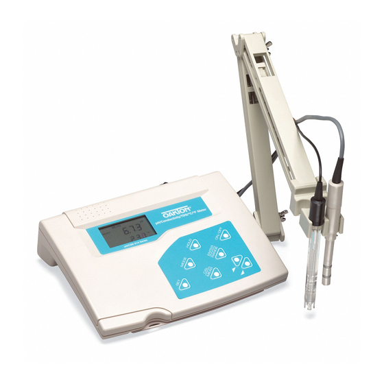
1. Starting up Thank you for purchasing an OAKTON ® pH/CON 510 benchtop meter. This multiparameter meter reads pH, mV, Conductivity, Total Dissolved Solids (TDS), and temperature (°C or °F). It is microprocessor controlled, user-friendly and reliable. Keypad See Figure 1. -
Page 4: Display
Display See Figure 2. The OAKTON ® pH/CON 510 meter features a large dual display that shows the measured parameter in the primary display, plus temperature in °C or °F in the secondary display. It also features mode annunciators that describe the meter’s functions. -
Page 5: Electrode Holder Arm
Electrode Holder Arm Bottom of meter The electrode holder is included in the same box as the meter. Shipping position To attach the electrode holder to the meter: The electrode holder base attached to the bottom of the meter comes in the ship- ping position. -
Page 6: Electrode Holder Arm
To install the electrode arm, turn meter back to the upright position. See Figure 6. Line up the hole on the base of the electrode holder arm with the peg on the electrode holder base. Slide the hole securely onto the electrode holder base. See Figure 7. -
Page 7: Probe Connections
Probe connections See Figure 9 . Your meter includes two probes: CON/TEMP • pH electrode with BNC connector • conductivity/TDS/temperature probe with a notched Figure 9 6-pin connector The temperature sensing element built into the conductiv- ity/TDS probe will also compensate for pH readings as long as both probes are in your solution at the same time. -
Page 8: Calibration
2. Calibration Important Information on Meter Calibration When you recalibrate your meter, old calibration points are replaced on a “point by point” basis in pH, and on a “range by range” basis in conductivity or TDS. For example: • pH: if you previously calibrated your meter at pH 4.01, 7.00, and 10.01, and you recalibrate at pH 7.00, the meter retains the old calibration data at pH 4.01 and pH 10.01. -
Page 9: Ph Calibration
pH calibration We recommend that you perform at least a 2-point calibra- tion using standard buffers that bracket (one above and one below) the expected sample range. Preparing for pH calibration This meter is capable of up to 5-point pH calibration to ensure accuracy across the entire pH range of the meter. -
Page 10: Ph Calibration
To calibrate pH: If necessary, press the MODE key to select pH measurement mode. The pH indicator appears in the upper right hand corner of the display. MEAS See Figure 10 READY Rinse the pH electrode thoroughly with de-ionized water or a rinse solution. -
Page 11: Conductivity/Tds Calibration
Conductivity/TDS calibration This meter is capable of up to 5-point conductivity or TDS calibration at one point per range: Conductivity: TDS: 0.00-19.99 µS 0.00-9.99 ppm 0.0-199.9 µS 10.0-99.9 ppm 0-1999 µS 100-999 ppm 0.00-19.99 mS 1.00-9.99 ppt 0.0-199.9 mS 10.0-199.9 ppt If you are measuring values in more than one range, make sure to calibrate each of the ranges you are measuring. -
Page 12: Conductivity/Tds Calibration
To calibrate conductivity or TDS: If necessary, press the MODE key to select conductivity or MEAS TDS mode. READY See Figure 13 Rinse the probe thoroughly with de-ionized water or a rinse solution, then rinse with a small amount of calibration standard. -
Page 13: Temperature Calibration
Temperature calibration The temperature sensor (located in the conductivity/TDS cell) is factory calibrated. Calibrate your sensor only if you suspect sensor drift that may have occurred over a long period of time or if you have a replacement probe. Temperature calibration Make sure the conductivity/TDS cell (or alternative tem- perature element) is attached to the 6-pin connector. -
Page 14: Measurement
3. Measurement Taking pH Measurements To take readings: Rinse the pH electrode with deionized or distilled water before use to remove any impurities adhering to the probe body. If the pH electrode has dehydrated, soak it for 30 minutes in electrode storage solution or a 2M–4M KCl solution. -
Page 15: Mv Measurements
–600 to 600 mV. You need to order an ORP or ion selective electrode with a BNC connector separately—sae page 43 or contact your OAKTON distributor for information. To take readings: . If necessary, press the MODE key to choose the mV mode. -
Page 16: Conductivity /Tds Measurements
Taking Conductivity or TDS Measurements To take readings: Rinse the probe with deionized or distilled water before use to remove any impurities adhering to the probe body. Shake or air dry. To avoid contamination or dilution of your sample, rinse probe with a small volume of your sample liquid. -
Page 17: Hold Function/Ready Indicator/Auto Endpoint
HOLD function This feature lets you freeze your reading for a delayed obser- vation. HOLD can be used any time when in MEAS mode. To hold a measurement, press the HOLD key while in measurement mode. "HOLD" will appear on the MEAS display. -
Page 18: Using Manual Ranging Function: Conductivity/Tds
Using manual ranging function: conductivity or TDS When shipped from the factory, your meter automatically selects the range in which your readings appear. The manual ranging function lets you select the specific range in which you want to work. From measurement mode: To select the desired measuring range, press the RANGE key while in Conductivity (or TDS) measurement mode. -
Page 19: Selecting Manual Temperature Compensation: Conductivity /Tds
Selecting manual temperature compensation: conductivity or TDS For manual temperature compensation in conductivity or TDS mode, you must: SETUP Deactivate the temperature element built into the conductivity/TDS probe. Select a manual temperature compensation value (see page 21). You can deactivate the temperature element (select manual temperature compensation) in Set Up Program P7.3. -
Page 20: Selecting A Manual Temperature Compensation Value
Selecting a manual temperature compensation value To use manual temperature compensation, you need to enter the temperature value of your process into the meter. This is the value at which readings will manually temperature com- pensate. You can select any temperature between 0 and 100°C (32 and 212°F). - Page 21 starting up calibration measurement setup mode electrode care troubleshooting specifications accessories appendixes warranty return of items...
-
Page 22: Advanced Setup Mode
Set up Mode SETUP The Set up mode lets you customize your meter’s preferences and defaults. Your OAKTON meter features different sub groups that organize all Set up parameters. This meter blanks out sub groups that do not apply to the measurement mode [conductivity/TDS or pH] you are in when you enter Set up mode. - Page 23 Set up mode overview Press the SET key to enter Set up mode. Press the keys to scroll through sub groups. Sub groups available from pH measurement mode: P1.0: Viewing pH calibration data SETUP P1.1 View previous pH calibration data (pH 1.68) P1.2 View previous pH calibration data (pH 4.01) P1.3 View previous pH calibration data (pH 7.00 or 6.86) P1.4 View previous pH calibration data (pH 10.01 or 9.18)
- Page 24 Sub groups available from conductivity or TDS measurement mode: P5.0: Viewing conductivity or TDS calibration data SETUP P5.1 View conductivity/TDS calibration data R1 R1 = 0.00-19.99 µS / 0.00-9.99 ppm P5.2 View conductivity/TDS calibration data R2 R2 = 0.0-199.9 µS / 10.0-99.9 ppm P5.3 View conductivity/TDS calibration data R3 R3 = 0-1999 µS / 100-999 ppm P5.4 View conductivity/TDS calibration data R4...
-
Page 25: P1.0: Viewing Previous Ph Calibration Data
P1.0: Viewing previous pH calibration data This mode lets you recall previous pH calibration data, which lets you know at which points this meter was previously cali- brated. This is a “view only” mode. From measurement mode: SETUP Press the Mode key to select pH measurement mode. Press the SET key to enter Set Up mode. -
Page 26: P2.0: Viewing Ph Electrode Data
P2.0: Viewing pH electrode data Program 2 has two “view only”options that lets you check the pH electrode parameters for diagnostic purposes. It lets you view: SETUP P2.1: Electrode offset P2.2 Electrode slope From measurement mode Press the Mode key to select pH measurement mode. Press the SET key to enter Set Up mode. -
Page 27: P3.0: Ph Configuration
P3.0: pH configuration P3.1: READY indicator and auto endpoint function This program lets you select READY indicator on, READY indicator off, or Auto endpoint function on. From measurement mode Press the Mode key to select pH measurement mode. Press SET key to enter Set Up mode. Press the keys to scroll through subgroups until you view parameter P3.0. -
Page 28: P3.3: Selecting Nist Or Usa Buffer Sets
P3.3: Selecting NIST or USA buffer sets Program P3.3 lets you select between the following calibration buffer sets: SETUP USA: pH 1.68, 4.01, 7.00, 10.01, 12.45 NIST: pH 1.68, 4.01, 6.86, 9.18, 12.45 Factory default is the USA buffer set. From measurement mode Press the Mode key to select pH measurement mode. -
Page 29: P4.0: Resetting To Factory Default Settings (Ph)
P4.0: Resetting to factory default settings (pH) This program lets you reset all pH parameters to factory default settings. This clears all calibration data any other pH SETUP MEAS set up functions you might have changed.The following set- tings will remain as you have set them: •... -
Page 30: P5.0: Viewing Previous Con./Tds Calibration Data
P5.0: Viewing previous conductivity (TDS) calibration data This mode lets you recall previous conductivity or TDS calibration data, which lets you know at which points this meter was previously calibrated. This is a “view only” mode. SETUP From measurement mode: Press the Mode key to select conductivity (TDS) measure- ment mode. -
Page 31: P6.0: Viewing Con./Tds Probe Data
P6.0: Viewing conductivity (TDS) probe data SETUP Program 6 has five "view only" options that let you check your conductivity/TDS probe’s parameters for diagnostic purposes. These options show you the effective cell constant for each range. The cell constant is adjusted according to your calibration. -
Page 32: P7.0: Conductivity/Tds Configuration
P7.0: Conductivity (TDS) configuration P7.1: READY indicator and auto endpoint function This program lets you select READY indicator on, READY indicator off, or Auto endpoint function on. READY indicator on indicates when reading is stable. READY indicator off gives faster meter response. Auto endpoint function on “holds”... -
Page 33: P7.2 Selecting °C Or °F
P7.2 Selecting °C or °F SETUP This meter lets you select between °C and °F units for temperature readings. From measurement mode Press the Mode key to select conductivity (TDS) measurement mode. Press SET key to enter Set Up mode. Figure 49 Press the keys to scroll through subgroups... -
Page 34: P7.4 Setting The Tds Factor
P7.4 Setting the TDS factor The concentration of salts dissolved in solution increases the conductivity of that solution. This relationship varies from salt to salt and is roughly linear over a given range for a given salt. The TDS conversion factor is the number used by the meter to convert from conductivity to TDS. -
Page 35: P8.0: Temperature Settings
P8.0: Temperature Settings SETUP P8.1 Selecting the temperature coefficient The temperature coefficient is the amount of change in conduc- tivity per degree of temperature. Entering the exact temperature coefficient of your solution lets you accurately compensate tem- perature for almost any solution. You can adjust 0.0 to 10.0% per °C or °F. -
Page 36: P9.0: Resetting To Factory Default Settings (Con./Tds)
P9.0: Resetting to factory default settings (conductivity or TDS) This program lets you reset all conductivity and/or TDS para- meters to factory default settings. This clears all calibration data any other conductivity set up functions you might have changed. The following settings will remain as you have set them: •... -
Page 37: Probe Care
Use 2 or 3 point calibration to test your electrode perfor- mance. If you do not get good readings, use a different pH electrode to confirm the meter is working properly. If the results are still not satisfactory, consult your OAKTON distributor. Electrode Maintenance pH electrodes are susceptible to dirt dehydration and contamination. -
Page 38: Electrode Cleaning
General dirt and light oil coatings. Soak the electrode for several hours in OAKTON general purpose electrode cleaning solutions. Rinse in deionized or distilled water. c. Oil/Grease Films Wash the electrode pH bulb in a little dish washing deter- gent and water. -
Page 39: Troubleshooting
10. Troubleshooting Error Messages The following table provides a guideline to enable diagnosis of possible problems indicated by the messages generated by the OAKTON pH/CON 510 meter. The table also provides possible solutions to the problems encountered. Error Message Indicates... -
Page 40: Troubleshooting
Troubleshooting Problem Cause Solution General Troubleshooting Nothing is displayed when A. AC outlet power not A.Switch on the power supply the ON/OFF key is selected. switched on. B. AC adapter socket not B. Re-insert AC adapter socket. inserted properly. pH Troubleshooting Unstable reading A. -
Page 41: Specifications
12. Specifications Mode Temperature Conductivity 0 to 19.99 µS 0.00 to 9.99 ppm 0 to 199.9 µS 10.0 to 99.9 ppm –2.00 to –600 to 0 to 100°C / Range 0 to 1999 µS 100 to 999 ppm 16.00 pH +600 mV 32.0 to 212°F 0 to 19.99 mS... -
Page 42: Accessories
WD-00654-08 pH 10.01 calibration buffer, 1 pint. WD-00654-12 pH 12.45 calibration buffer, 1 pint. accessories OAKTON “Singles” pH calibration solution pouches To order OAKTON accessories; pH solutions have ±0.01 pH accuracy at 25°C. contact your OAKTON appendixes Shpg wt 1.1 lb per box of 20 distributor, or visit WD-35653-01 pH 4.01 calibration buffer pouches... -
Page 43: Appendix 1: Conductivity To Tds Conversion Factors
Appendix 1: Conductivity to TDS Conversion Factors 1. Factor —the conductivity to ppm TDS conversion factor. Multiply conductivity by this factor to get ppm TDS for the type of TDS reading needed. 2. 442 —a formulation that most closely represents the con- ductivity to ppm relationship, on average, for naturally occurring fresh water. -
Page 44: Appendix 2: Calculating Temperature Coefficients
Appendix 2: Calculating Temperature Coefficients To determine the temperature coefficient of your sample solution use this formula: TC = 100 x CT2 - CT1 CT1(T2 - 25) - CT2(T1 - 25) TC = Temperature coefficient CT1 =Conductivity at Temp. 1 CT2 = Conductivity at Temp. -
Page 45: Appendix 3: Ph And Temperature
(high pH). For acidic samples, use standard buffers of pH 7.00 and pH 4.01. For basic samples, use standards of pH 7.00 and pH 10.01. Use a 3 (or more) point calibration when the sample pH is completely unknown. Contact your OAKTON ® distributor for information on pH buffer and calibration solutions. -
Page 46: Appendix 4: Meter Factory Default Settings
Appendix 4: Meter factory default settings Resetting the meter to factory default settings clears all calibration data and most other set up functions you might have changed. The following settings will remain as you have set them: • temperature unit of measure (°C or °F) •... -
Page 47: Warranty
OAKTON alone will determine if the product problem is due to deviations or customer misuse. Return of items Authorization must be obtained from our Customer Service Department before returning items for any reason.
Need help?
Do you have a question about the pH/CON 510 series and is the answer not in the manual?
Questions and answers