Advertisement
Quick Links
Introduction
Thank you for purchasing this Bumper/
Guard for your tiller. The Bumper/Guard
is designed to protect the engine and tiller
from costly impact damage.
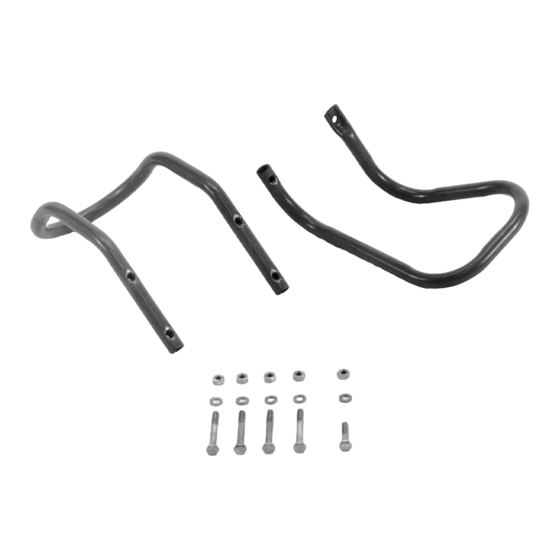
Kit Contents
(see Fig. 1)
Ref.
Part No.
Description
1
1904540
Bumper, Front ........1
2
1904539
Bumper, Side ..........1
3
1111608
Hex Hd. Screw,
5/16-18 x 2-1/2....4
4
1100799
Hex Hd. Screw,
5/16-18 x 1-1/2....1
5
1100242
Washer, Spring
Lock, 5/16............5
6
1186230
Hex Nut, 5/16-18 ....5
CAUTION
TO PREVENT INJURY FROM MOVING
PARTS OR HOT SURFACES:
• Stop the engine and wait for all mov-
ing parts to stop.
• Disconnect the spark plug wire from
the spark plug and allow the muffler
to cool.
Preparation
• Stop the engine, wait for all moving
parts to stop and disconnect the spark
plug wire. Allow the muffler to cool.
• You will need two 1/2-in. wrenches.
• References to "Left" and "Right" are
given from the operator's position
behind the handlebars.
• The engine shown in the figures may
not match the engine on your tiller.
Qty.
Figure 1
Installation Steps
1. On the right side (muffler side) of the
engine, position the rear leg of the
side bumper on the top edge of the
engine support bracket as shown in
Fig. 2. Then insert the new 1-1/2"
long screw (A) up through the holes
in the support bracket and the rear
leg. Add a new spring lockwasher
and hex nut and tighten finger-tight.
NOTE: If engine is equipped with a
throttle cable, route the cable above
the legs of the bumper.
2. Do not attach the front leg of the
bumper at this time, but do check that
the mounting hole in the front leg is
aligned with the front hole in the
engine support bracket (where front
of engine is attached to support
bracket). If so, go on to Step 3. If
not, move the rear leg to another hole
(if so equipped) in the support brack-
et and re-check the alignment.
Tiller Bumper/Guard
OEM-290-256 / 290-256-081
1
3
Figure 3: Remove engine mounting screws
(B) from right side.
6
5
4
Rear leg
Align front leg with
front mounting
A
Figure 2: Loosely attach rear leg of side
bumper to top of engine support bracket.
B
2
screw.
Advertisement

Related Manuals for Troy-Bilt OEM-290-256


Summary of Contents for Troy-Bilt OEM-290-256
- Page 1 Tiller Bumper/Guard OEM-290-256 / 290-256-081 Introduction Thank you for purchasing this Bumper/ Guard for your tiller. The Bumper/Guard is designed to protect the engine and tiller from costly impact damage. Kit Contents (see Fig. 1) Ref. Part No. Description Qty. 1904540 Bumper, Front ..1 1904539...
- Page 2 View from beneath 7. Tighten all of the bumper/guard mount- engine ing screws securely. For customer assistance, visit www.troybilt.com, contact your nearest authorized dealer or: TROY-BILT LLC, P.O. BOX 361131, CLEVELAND, OHIO 44136-0019, 1-866-840-6483 Printed in U.S.A. Form 769-00136 (03/2002)