Table of Contents
Advertisement
Quick Links
Advertisement
Table of Contents

Related Manuals for Painless Performance 60502

Summary of Contents for Painless Performance 60502
- Page 1 P/N 60502 & 60505 1994/1995 GM LT1 FUEL INJECTION WIRE HARNESS INSTALLATION INSTRUCTIONS Manual P/N 90517 Copyright © May 2002 PAINLESS PERFORMANCE PRODUCTS 2501 Ludelle Street - Fort Worth, Texas 76105-1036 - (817) 244-6898 E-Mail: tech@painlessperformance.com Web: painless@painlessperformance.com...
- Page 2 We have attempted to provide you with as accurate instructions as possible, and are always concerned about corrections or improvements that can be made. If you have found any errors or omissions, or if you simply have comments or suggestions concerning these instructions, please write us at the address on the cover and let us know about them.
-
Page 3: Table Of Contents
TABLE OF CONTENTS INTRODUCTION.......................... ABOUT THESE INSTRUCTIONS....................TOOLS NEEDED.......................... PRE-INSTALLATION AND HARNESS ROUTING GUIDELINES........... TRANSMISSION FUNCTION..................GET TO KNOW THE ENGINE THAT YOU ARE USING........... GENERAL INSTALLATION INSTRUCTIONS................GROUNDING THE VEHICLE..................ROUGH INSTALLATION....................4 HARNESS ATTACHMENT................... TERMINAL INSTALLATION INSTRUCTIONS............GM 94 & 95 LT1 SYSTEM WIRE HARNESS INSTALLATION..........CONTENTS OF THE 60502 OR 60505 WIRE HARNESS KIT........ - Page 4 14 & 15 INTRODUCTION You have purchased what we at Painless Performance Products believe to be the most up-to-date and easiest-to- install automotive fuel injection harness on the market. It is designed for easy installation, even if you have no electrical experience.
-
Page 5: Tools Needed
TOOLS NEEDED In addition to your regular tools, you will need, at least, the following: Crimping tool NOTE: USE A QUALITY TOOL TO AVOID OVER-CRIMPING. Wire stripper Continuity tester CAUTION: DO NOT USE A TEST LIGHT TO TEST THE COMPUTER OR SENSOR WIRING OR YOU WILL DAMAGE THE COMPUTER. -
Page 6: Get To Know The Engine That You Are Using
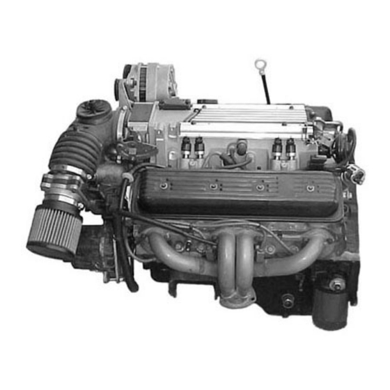
To keep the check engine light from coming on you will need to plug in a canister purge solenoid and air pump relay to the wires in the dash section. (The computer looks for signals from these controls and does not care if the actual devices are installed.) YOU SHOULD GET TO KNOW THE PARTICULAR ENGINE YOU ARE USING: NOTE: The 94 &... -
Page 7: General Installation Instructions
LT1 Fuel Injection Harness (94 & 95) Part # 60502 or 60505 Main Computer......Service#16188051 EGR. Solenoid........ Delco# 214-396 Brake Switch........GM# 25524845 Gear Indicator Switch....GM# 15705308 or Intake Air Temperature.....GM# 12110319 Delco #D2286A Ignition Module......Delco# D-1986-A MAP Sensor ........GM# 16137039 Fuel Pump Relay...GM# 14089936 Delco# 15-8240 Idle Air Control ........GM# 17113099 Coolant Temperature Sensor ..GM# 25036979 Knock Sensor ........Delco# 213-96... -
Page 8: Rough Installation
ROUGH INSTALLATION CAUTION: DISCONNECT THE POWER FROM YOUR VEHICLE BY REMOVING THE NEGATIVE BATTERY CABLE FROM THE BATTERY. Note: Make no wire connections or permanent mounting of any kind at this time. 5.2.1 Position the computer and sensors in their intend locations. 5.2.2 Drill a 1-5/8"... -
Page 9: Gm 94 & 95 Lt1 System Wire Harness Installation
Take inventory to see that you have everything you are supposed to have in this kit. If anything is missing, contact the dealer where you obtained the kit or contact Painless Performance at (817) 244-6898. The kit should contain the following items: The main wire harness with the connectors already on the ends of most of the wires. -
Page 10: Figure 6.2 Brake Switch Connection
WHEN THE KEY IS IN THE START AND RUN POSITION. This is the power wire for the fuel injection harness. If the pink wire is connected correctly, the check engine light will come on when the ignition is "ON or START". Locate the Orn/Blk and Blk/Wht wires in the dash group. -
Page 11: Figure 6.3 Brake Switch Relay
FIGURE 6.3 Brake Switch Relay FIGURE 6.4 Gear Indicator Switch... -
Page 12: Figure 6.5 Air Pump Relay Connector
If you are using the recommended brake switch then you will wire it according to Figure 6.2. The pink wire to the back of the switch in the illustration is the wire that has power on it whether or not the brake is being applied. CAUTION: FAILURE TO WIRE THIS SWITCH CORRECTLY WILL RESULT IN A DANGEROUS SITUATION ON THE VEHICLE. -
Page 13: Engine Group Installation
FIGURE 6.8 Fuel Pump Relay Connector FIGURE 6.7 Air Pump Connection ENGINE GROUP INSTALLATION The engine group is designed to be separated into left side (driver) and right side (passenger) sections. Each side is tie-wrapped separately, BUT NOT LABELED. The right side of the engine has the connectors for the idle air control, throttle position sensor, distributor, and map sensor, all of which ARE labeled. -
Page 14: Figure 6.9 Egr Solenoid
6.3.6 Engine Section Connections WIRE COLOR # OF POSITIONS LABELED CONNECT TO: IN CONNECTOR Brown, Gray EGR Solenoid Blue Knock Knock Sensor Purple/White, Tan/White, Brown, Black Driver Side Oxy Left Oxygen Sensor Purple, Tan, Brown, Black Pass. Side Oxy Right Oxygen Sensor Ring Terminal (2) Starter B+ Starter Solenoid... -
Page 15: Figure 6.11 Oxygen Sensor
FIGURE 6.11 Oxygen Sensor FIGURE 6.12 MAP Sensor FIGURE 6.13 Injectors 1, 3, 5, 7 FIGURE 6.14 Injectors 2, 4, 6, 8 FIGURE 6.16 IAC FIGURE 6.15 TPS Sensor... -
Page 16: Figure 6.17 Maf Sensor
FIGURE 6.18 Distributor FIGURE 6.17 MAF Sensor FIGURE 6.19 Ignition Module FIGURE 6.20 Coil FIGURE 6.21 ECT Sensor FIGURE 6.22 IAT Sensor... -
Page 17: Tail Section Installation
TAIL SECTION INSTALLATION 6.4.1 Locate the tail section that you earlier separated from the engine group. Begin routing it towards the rear of the vehicle. Be sure to avoid all sharp edges, moving or hot parts, or anything else that may damage the harness. -
Page 18: The "Check Engine" Light
FIGURE 7.1 Fuse Identification THE "CHECK ENGINE" LIGHT Normally, the "check engine" light should come on when the ignition is turned on, then go out a few moments after the engine starts running. If it reappears, or stays on while the engine is running, the computer has detected a problem and a trouble code has been set. - Page 19 7.2.6 Trouble Code Chart, Diagnostic Trouble Code (DTC) DTC 11 = Malfunction Indicator Lamp DTC 13 = Bank 1 (left) Heated Oxygen Sensor (HO2S) Open Circuit DTC 14 = Engine Coolant Temperature (ETC) Sensor Circuit (Signal Voltage Low) Overheated DTC 15 = Engine Coolant Temperature (ETC) Sensor Circuit (Signal Voltage High) Engine cold DTC 16 = Distributor Ignition System (Low Resolution Pulse) DTC 18 = Injector Circuits DTC 21 = Throttle Position (TP) Sensor Circuit (Signal Voltage High)
-
Page 20: When To Call "Painless Wiring" Tech Line
If you have any questions concerning the installation of this harness or having trouble in general, feel free to call Painless Performance Products' tech line at (817) 560-8324. Calls are answered from 8am to 5pm central time, Monday thru Friday, except holidays. Email questions to... - Page 21 Painless Performance will repair or replace defective products without charge during the first 12 months from the purchase date. No products will be considered for warranty without a copy of the purchase receipt showing the sellers name, address and date of purchase.
Need help?
Do you have a question about the 60502 and is the answer not in the manual?
Questions and answers