Table of Contents
Advertisement
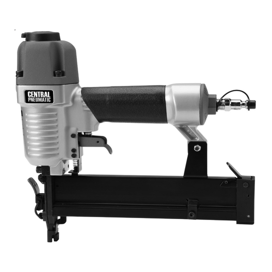
1/4" 18-GAUGE CROWN
SET UP AND OPERATING INSTRUCTIONS
Visit our website at: http://www.harborfreight.com
Read and understand tool labels and
manual. Failure to follow warnings could
result in DEATH or SERIOUS INJURY.
SAVE THIS MANUAL.
©
Copyright
2010 by Harbor Freight Tools
contained herein may be reproduced in any shape or form without the express written consent of
Harbor Freight Tools. Diagrams within this manual may not be drawn proportionally. Due to continuing
improvements, actual product may differ slightly from the product described herein. Tools required for
assembly and service may not be included.
For technical questions or replacement parts, please call 1-800-444-3353.
AIR STAPLER
Model
®
. All rights reserved. No portion of this manual or any artwork
68018
Advertisement
Table of Contents

Summary of Contents for CentralPneumatic 68018
- Page 1 1/4” 18-GAUGE CROWN AIR STAPLER Model 68018 SET UP AND OPERATING INSTRUCTIONS Visit our website at: http://www.harborfreight.com Read and understand tool labels and manual. Failure to follow warnings could result in DEATH or SERIOUS INJURY. SAVE THIS MANUAL. © ® Copyright 2010 by Harbor Freight Tools .
-
Page 2: Symbol Definitions
SAVE THIS MANUAL CAUTION, without the safety alert symbol, is Keep this manual for the safety warnings used to address practices not and precautions, assembly, operating, related to personal injury. inspection, maintenance and cleaning procedures. Write the product’s serial number Symbol Definitions in the back of the manual near the assembly diagram (or month and year of purchase if... -
Page 3: Work Area
WARNING – When using tools, basic Avoid unintentional starting. Be precautions should always be followed, sure the trigger is released before including the following: connecting to the air supply. Do not carry the tool with your finger on the General trigger or connect the tool to the air supply with the trigger pressed. -
Page 4: Air Source
Never carry the tool with finger on Use only accessories that are trigger, the tool is able to fire a fastener. identified by the manufacturer for the specific tool model. Use of an Tool use and care accessory not intended for use with the specific tool model, increases the risk of Use clamps or another practical way injury to persons. - Page 5 SAVE THESE c. Clearing a jam. d. Moving the tool to a new location. INSTRUCTIONS. 13. Do not make any modifications to tool. SAFETY INSTRUCTIONS Specific Safety Instructions 14. Refer to the tool maintenance instructions for detailed information on Operators and others in work area the proper maintenance of the tool.
- Page 6 23. Install in-line shutoff valve to allow particularly to the hands, arms and shoulders. immediate control over air supply in an To reduce the risk of vibration-related injury: emergency, even if a hose is ruptured. Anyone using vibrating tools regularly 24.
-
Page 7: Functional Description
to the Assembly Diagram near the end of FUNCTIONAL DESCRIPTION Functional Description this manual. Specifications Unpacking Maximum Air 120 PSI When unpacking, make sure the item Pressure is intact and undamaged. If any parts are Air Inlet 1/4”-18 NPT missing or broken, please call Harbor Freight Fastener 5/8”... - Page 8 Air Tool & Spray Gun Portable Setup Page 8 For technical questions, please call 1-800-444-3353. SKU 68018...
- Page 9 Air Tool & Spray Gun Stationary Setup SKU 68018 For technical questions, please call 1-800-444-3353. Page 9...
-
Page 10: Work Piece And Work Area Set Up
tool. Other components, such as coupler and release Trigger to prevent plug and industrial-grade quick coupler, accidental operation. will make operation more efficient, but Note: Residual air pressure should not be are not required. present after the tool is disconnected WARNING! TO PREVENT SERIOUS from the air supply. -
Page 11: Loading Staples
parts. If any problems are found, again. The tool must not cycle (fire). do not use tool until repaired. If it fails to act in the manner explained in bold, have it repaired by a qualified Testing the Single Sequential Safety service technician. - Page 12 To fire, open the shut-off valve, place the Safety against the workpiece. The Stapler should not fire if the nose is not depressed. Once depressed, gently and briefly squeeze the Trigger once. Do not fire repeatedly. Staples could bounce off of one another, damaging the work piece or causing PERSONAL INJURY.
-
Page 13: User Maintenance
USER-MAINTENANCE Note: These procedures are in addition to User-Maintenance Instructions the regular checks and maintenance explained as part of the regular operation of the air-operated tool. Procedures not specifically explained in this manual must Daily - Air Supply Maintenance: be performed only by a Every day, perform maintenance on the qualified technician. - Page 14 Hold the Stapler pointed away from you and any other people or fragile objects and lift up the Cover Latch (43). Pull up on the Switch, lifting the Cover Plate (44) up off the Drive Guide (41) and remove jammed fasteners. Inspect Drive Guide for bends or breakage.
-
Page 15: Troubleshooting
Troubleshooting Troubleshooting Problem Possible Causes Likely Solutions Insufficient 1. Not enough air pressure. 1. Check for loose connections and make sure that air fastener depth. supply is providing enough air pressure (PSI) to the tool’s air inlet. Do not exceed maximum 120 PSI air pressure. -
Page 16: Parts List
PLEASE READ THE FOLLOWING CAREFULLY THE MANUFACTURER AND/OR DISTRIBUTOR HAS PROVIDED THE PARTS LIST AND ASSEMBLY DIAGRAM IN THIS MANUAL AS A REFERENCE TOOL ONLY. NEITHER THE MANUFACTURER OR DISTRIBUTOR MAKES ANY REPRESENTATION OR WARRANTY OF ANY KIND TO THE BUYER THAT HE OR SHE IS QUALIFIED TO MAKE ANY REPAIRS TO THE PRODUCT, OR THAT HE OR SHE IS QUALIFIED TO REPLACE ANY PARTS OF THE PRODUCT. -
Page 17: Assembly Diagram
ASSEMBLY DIAGRAM Assembly Diagram 45 46 Record Product’s Serial Number Here: Note: If product has no serial number, record month and year of purchase instead. Note: Some parts are listed and shown for illustration purposes only, and are not available individually as replacement parts. - Page 18 Limited 1 Year Warranty Harbor Freight Tools Co. makes every effort to assure that its products meet high quality and durability standards, and warrants to the original purchaser that this product is free from defects in materials and workmanship for the period of one year from the date of purchase (90 days if used by a professional contractor or if used as rental equipment).
Need help?
Do you have a question about the 68018 and is the answer not in the manual?
Questions and answers