Table of Contents
Advertisement
Quick Links
Owner's Manual
BN°
TI
UAL
900 Series
17
ETLL
OTATI
Inch Tine Width
TI
iT
ES
Model No.
917.299081
• EspaSol,
p. 23
This product has a low emission
engine
which
operates
differently
from previously
built engines.
Before
you start the
engine,
read and understand
this Owner's
Manual.
IMPORTANT:
Read and follow all Safety
Rules and Instructions before
operating
this equipment.
Sears, Roebuck
and Co., Hoffman
Estates, IL 60179
Visit our Craftsman
website:www.sears.com/craftsman
U.S.A.
428422 Rev. 1
Advertisement
Table of Contents
Troubleshooting

Related Manuals for Craftsman 917.299081


Summary of Contents for Craftsman 917.299081
- Page 1 Before you start the engine, read and understand this Owner's Manual. IMPORTANT: Read and follow all Safety Rules and Instructions before operating this equipment. U.S.A. Sears, Roebuck and Co., Hoffman Estates, IL 60179 Visit our Craftsman website:www.sears.com/craftsman 428422 Rev. 1...
-
Page 2: Limited Two-Year Warranty
• If this Craftsman Tiller is used for commercial or rental purposes, this Warranty plies for only thirty (30) days from the date of purchase. Warranty... -
Page 3: Operation
• Use extension cords and receptacles • Never operate the machine at high as specified by the manufacturer for all speeds on slippery surfaces. Look be- units with electric drive motors or elec- hind and use care when backing. tric starting motors. -
Page 4: Product Specifications
NGK-BPR6ES REPAIR PROTECTION (Gap: .030"/0.76mm) TOROH-F6RTC AGREEMENTS Congratulations on making a smart pur- CONGRATULATIONS on your purchase chase. Your new Craftsman@ product of a Sears Tiller. It has been designed, designed and manufactured for years of engineered and manufactured to give you dependable operation. -
Page 5: Contents Of Hardware Pack
These accessories were available when the tiller was purchased. They are also avail- able at most Sears Retail outlets and Service Centers. Most Sears Stores can order repair parts for you when you provide the model number of your tiller. ENGINE SPARK PLUG MUFFLER... - Page 6 Your new tiller has been assembled at the factory with the exception of those parts left unassembled for shipping purposes. To ensure safe and proper operation of your tiller all parts and hardware you assemble must be tightened securely. Use the correct tools as necessary to insure...
-
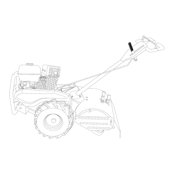
Page 7: Check Tire Pressure
CONNECT SHIFT ROD Rotate handle assembly down. Insert 1. Insert end of shift rod into hole of shift rear carriage bolt first, with head of lever indicator. bolt on LH. side of tiller and loosely assemble Iocknut. 2. Insert hairpin clip through hole of shift rod to secure. - Page 8 These symbols may appear on your Tiller or in literature supplied with the product. Learn and understand their meaning. KNOW YOUR TILLER READ THIS OWNER'S MANUAL AND SAFETY RULES BEFORE OPERATING YOUR TILLER. Compare the illustrations with your tiller to familiarize yourself with the location various...
- Page 9 The operation of any tiller can result in foreign objects thrown into the eyes, which can result in severe eye damage. Always wear safety glasses or eye shields before starting your tiller and while tilling. We recommend standard safety glasses or a wide vision safety mask...
-
Page 10: Drag Stake
DRAG STAKE Lift handle to raise tines out of ground. Swing the handle in the opposite direc- The drag stake should be raised when tion you wish to turn, being careful tilling the counter rotating (_) till position. keep feet and legs away from tines. The drag stake should be lowered... -
Page 11: Before Starting
AROUND TOWN AI_,CAUTION: Fill to within 1/2 inch of top Disconnect spark plug wire. of fuel tank to prevent spills and to allow Drain fuel tank. for fuel expansion. If gasoline is acciden- Transport in upright position to prevent tally spilled, move machine away from... - Page 12 If the choke lever has been moved • You will find tilling much easier if you the "ON" position to start the engine, leave a row untilled between passes. gradually move it to the opposite posi- Then go back between tilled rows.There tion as the engine...
-
Page 13: Tine Shear Pins
TINE SHEAR PINS The tine assemblies on your tiller are secured to the tine shaft with shear pins (See "TINE REPLACEMENT" in the Service and Adjustments section of this manual). If the tiller is unusually overloaded jammed, the shear pins are designed break before internal damage... - Page 14 MAI.'rE.A.CE / / / / / sc. ou, /JSZ oZ#/ SERVICE DATES REGULAR SERVICE Check Engine 0il Level Change Engine Oil _1,2 0il Pivot Points Inspect Spark Arrester / Muffler Inspect Air Screen Clean or Replace Air Cleaner Cartridge Clean Engine Cylinder Fins Replace Spark Plug 1 - Change more often when operating under a heavy load or in high ambient temperatures.
-
Page 15: Air Cleaner
_kCAUTION: Disconnect spark plug Remove oil filler plug. Be careful to allow dirt to enter the engine. wire before performing any maintenance (except carburetor adjustment) to prevent Refill engine with oil. See "CHECK accidental starting of engine. ENGINE OIL LEVEE' in the Operation section of this manual. -
Page 16: Cooling System
COOLING SYSTEM SPARK PLUG Your engine is air cooled. For proper Replace spark plugs at the beginning gine performance and long life keep your each tilling season or after every 25 hours engine clean. of use, whichever comes first. Spark plug •... - Page 17 Belt Guard TIRE CARE _CAUTION: When mounting tires, unless beads are seated, overinflation can cause Washer an explosion. (Located • Maintain 20 pounds of tire pressure. Behind tire pressures are not equal, tiller will Tire) pull to one side. • Keep tires free of gasoline or oil which can damage rubber.
-
Page 18: Tine Replacement
TINE REPLACEMENT To maintain the superb tilling perfor- mance of this machine the tines should ,_CAUT[ON: Tines are sharp. Wear be checked for sharpness, wear, and gloves or other protection when handling bending, particularly the tines which tines. are next to the transmission. If the gap A badly worn tine causes... - Page 19 ENGINE TO ADJUST CARBURETOR The carburetor has been preset at the Maintenance, repair, or replacement factory and adjustment should not be the emission control devices and systems, necessary. However, engine performance which are being done at the customers can be affected by differences in fuel, tem- pense, may be performed...
-
Page 20: Engine Fuel System
Immediately prepare your tiller for storage NOTE: Fuel stabilizer is an acceptable at the end of the season or if the unit will alternative in minimizing the formation not be used for 30 days or more. fuel gum deposits during storage. -
Page 21: Troubleshooting
TROUBLESHOOTING CHART: See appropriate section in manual unless directed to Sears service center PROBLEM CAUSE CORRECTION Will not start Fill fuel tank. Out of fuel. Fuel valve "OFF" Turn fuel valve to the "ON" position. Engine Switch "OFF" Turn engine switch to the "ON" position. Engine not "CHOKED"... - Page 22 TROUBLESHOOTING CHART: See appropriate section in manual unless directed to Sears service center PROBLEM CAUSE CORRECTION Excessive Ground too dry and hard. Moisten ground or wait for more favorable soil conditions bounce/ difficult Wheels and depth stake Adjust wheels and depth stake. handling incorrectly adjusted.
- Page 23 • Si la Cultivadora Craftsman se usa para fines de arriendo, esta garanfia se aplica solamente treinta (30) treintadias a partir de la fecha de compra. El Servicio de Garantia esta disponible...
- Page 24 MANTENIMIENTO Y ALMACENAIVIIENTO • Despues de pegarle a un objeto extraflo, pare el motor, remueva el alambre de la • Mantenga los accesorios y aditamentos bujia, inspeccione la cultivadora cuidadosa- la m&quina en buenas condiciones para el mente, para verificar si hay daflos, y repare funcionamiento.
- Page 25 Capacidad de gasotina: 3 Cuartos (2.8L) Congratulaciones por su buena compra. Sin ptomo, regular Su nuevo producto Craftsman® est& diseflado y fabricado para funcionar de modo fiable por Aceite (API-SG-SL): SAE 30 (Sobre 32°F) muchos aflos. Pero como todos los productos, (Capacidad:20 oz./0.6L)
- Page 26 Estos accesorios estaban disponibles cuando se compr6 la cultivadora. Tambien estan disponibles en la mayoria de las tiendas de Sears yen los centros de servicio. La mayoria de las tiendas Sears tambien pueden ordenar partes de repuesto para usted, si les proporciona el nOmero del modelo de su cultivadora.
- Page 27 Su cultivadora nueva ha sido montada en la f_tbrica, con la excepci6n de aquellas partes que se dejaron sin montar por razones de envio. Para asegurarse que la cultivadora operara en forma segura y adecuada, todas las partes y los articulos de ferreteria que monte tienen que estar apre- tados en forma segura.
- Page 28 Rote el conjunto del mango hacia abajo. In- Cotumna det serte el perno portador trasero primero, con Mango la cabeza del perno en el lado izquierdo de la cultivadora y ponga sueltamente la tuerca de seguridad. Cables Inserte el perno de pivote de la parte delan- tera de la placa y apriete en forma segura.
- Page 29 Estos simbolos pueden apareser sobre su cultivadora en la literature proporcionada con el pro- ducto, aprenda y comprenda sus significados. CONOZCA SU CULTIVADORA LEA ESTE MANUAL DEL DUENO Y LAS REGLAS DE SEGURIDAD ANTES DE OPERAR SU CULTWADORA Compare las ilustraciones con su cultivadora para familiarizarse con la ubicaci6n...
-
Page 30: Como Utilizar
La operaci6n de cualquier cultivadora puede hacer que salten objetos extraflos den- tro de sus ojos, Io que puede producir daflos graves en estos. Siempre use anteojos SEGURIDAD de seguridad o protecciones para los ojos antes de hacer arrancar su cultivadora mientras este labrando con ella. - Page 31 ESTACA DE ARRASTRE Cuando haya completado su vuelta, suelte La estaca de arrastre debe estar levantada la barra de control de la impulsi6n y baje el cuando este cultivando en el modo de contra mango. Ponga la palanca de cambio en la posici6n labrado y mueva el control de la rotaci6n (_).
-
Page 32: Antes De Arrancar
4. Mueva el control d e laaceleraci6n a la AGREGUE GASOLINA velocidad deseada. • Llene el estanque de combustible. Llene ENLA ClUDAD hasta la parte inferior del cuello de rel- leno del estanque de gasolina. No Io Ilene 1. Desconecte e l alambre de labujia. demasiado. - Page 33 CONSEJOS PARA LABRAR Mueve la palanca del regulador lejos ,_PRECAUCl6N: Antes de acostumbrarse de la posici6n ,,SLOW,, (lento), aproxi- madamente 1/3 de vuelta hacia manejar su cultivadora, empiece el uso de esta en el terreno con la aceleraci6n en la posici6n posici6n ,_FAST_ (rapido).
- Page 34 CULTIVO AJUSTE DE LAS RUEDAS PARA EL CULTIVO El cultivo quiere decir la destrucci6n de las malezas entre las hileras, para evitar que estas Ponga bloques debajo del lado derecho de le roben la nutrici6n y la humedad alas plantas. la cultivadora y remueva la abrazadera AI mismo tiempo, si se rompe la capa superior horqui!la y la clavija de horquilla de la rueda...
-
Page 35: Mantenimiento
/o//// MANTENIMIENTO /-_l LLENE LAS FECHAS DE MEDIDA /_X_OX_--_'7_od Q UEC oM LE -E IUo lo /o i SERVICIO REGULAR FECHAS DE SERVICIO Revisar et nivet del aceite del motor Cambiar et aceite del motor Aceitar los puntos de pivote Inspeccionar et supresor del sitenciador Inspeccionar la rejitta de aire Limpiar/cambiar el cartucho del fittro de aire... -
Page 36: Para Cambiar
Incline la cultivadora hacia adelante para ,_PRECAUCl6N:Desconecte el alambre de drenar el aceite. la bujia antes de dar mantenimiento (excepto Despues de que el aceite se haya drenado pot el ajuste del carburador) para evitar que el completamente, vuelva a colocar el tap6n motor arranque pot accidente. - Page 37 EL SISTEMA DE ENFRIAMIENTO LAS BUJIAS Este motor es un motor enfriado por aire. Para Reemplace las bujias al comienzo de la obtener un rendimiento adecuado del motor temporada de arado o despues de cada y una mayor vida Qtil, mant6ngalo limpio.
- Page 38 CUIDADO DE LAS LLANTAS Protecci6n de la correa Tuerca ,_PRECAUCI6N: Cuando monte las Ilantas, Hexagonal a menos que los talones esten asentados, si arandeta se inflan demasiado se puede producir una (Ubicadas explosi6n. detras de la • Mantenga 20 libras de presi6n en las Ilantas. Ilanta) Si la presi6n de las Ilantas no es la misma, la Tuerca de...
- Page 39 CAMBIO DE BRAZOS Para que esta m&quina pueda mantener un rendimiento excelente en el labrado, se _IPRECAUCl6N: Los brazos son afilados. deben revisar los brazos para verificar si Use guantes u otra protecci6n cuando maneje est&n afilados, desgastados o doblados, los brazos.
- Page 40 PARA AJUSTAR EL CARBURADOR EL MOTOR El carburador tiene un chorro de alta velocidad El mantenimiento, la reparaci6n o el y ha sido preajustado en la f&brica y no deberia reemplazo de los sistemas y dispositivos necesitar ajustes. Sin embargo, se pueden de control de emisi6n, Io cual se realiza...
-
Page 41: Aceite Del Motor
AVlSO: El estabilizador de combustible es una Inmediatamente prepare su cultivadora para el almacenamiento al final de la temporada o si la alternativa aceptable para reducir a un minimo unidad no se va a usar por 30 dias o m&s. la formaci6n de dep6sitos de goma en e! com- bustible durante el periodo de almacenamiento. - Page 42 IDENTIFICACION DE PROBLEMAS: Yea la secci6n apropiada en el manual a menos que este dirigido a un centro de servicio Sears. CORRECCION PROBLEMA CAUSA No arranca Se acab6 el combustible. Llene el tanque de combustible. La v&tvuta de combustible est& en Gire ta v&tvuta de combustible hasta la la posici6n -OFF,, (apagado) posici6n-ON>,...
- Page 43 IDENTIFICACION DE PROBLEMAS: Yea la secci6n apropiada en el manual a menos que este dirigido a un centro de servicio Sears. CORRECCION PROBLEMA CAUSA Controte el nivel de aceite/cambie el aceite. El motor El nivet de aceite esta bajo/el recalienta aceJte esta sucio.
- Page 44 TILLER - - MODEL NUMBER 917.299081 HANDLES KEY PART KEY PART DESCRIPTION DESCRIPTION 141406 Grip, Handle STD541437 Nut, Crowntock 3/8-16 110673X Grommet, Handle 19131611 Washer 13/32xlx11 127254X 109228X Lever, Lock, Handle Bar, Drive Control Assembly 6712J Cap, Vinyl 420524 Handle, Assemble 189347 Panel, Control 165197...
- Page 45 TILLER - - MODEL NUMBER 917.299081 MAINFRAME, LEFT SIDE ....-÷!. :_69 mainframe left PART PART DESCRIPTION DESCRIPTION STD541037 Nut, Hex 3/8-16 132801 Belt, V 432420 Shield, Inner Belt Guard 104679X Pulley, Idler 164329 Pin, Shift Lever 12000032 Ring, Klip 162756 Lever, Shift 159229...
- Page 46 TILLER - - MODEL NUMBER 917.299081 MAINFRAME, RIGHT SIDE mainframe righLLCT PART KEY PART DESCRIPTION DESCRIPTION 185190 Bumper Engine, (See Breakdown) 73970500 LOT Model No. Locknut, Hex, Flange 5/16-18 STD551031 PLM HK14600124P-BPQE2 Washer 11/32x11/16x16Ga. 74760512 74760528 Bolt, Fin Hex 5/16-18 unc x 1-3/4 Bolt, Hex 5/16-18 x 3/4 73510600 102332X...
- Page 47 TILLER - - MODEL NUMBER 917.299081 TRANSMISSION transmission PART PART DESCRIPTION DESCRIPTION 188240 Transmission Assembly (Includes 106388X Spacer 0.70 x 1.00 x 1.150 Key Nos. 2-52) 102121X Sprocket and Gear Assembly 188220 Shaft, Reduction (2nd) Gearcase, L.H. w/Bearing 102112X Screw, Whiz, Lock 5/16-18 x 3-1/2 (Includes Key No.
- Page 48 TILLER - - MODEL NUMBER 917.299081 TINE SHIELD 27 i tine shield 24 in rl PART PART DESCRIPTION DESCRIPTION 73900500 Nut, Lock Hex Flange 5/16-18 unc 74930632 Bolt, Hex 3/8-16 x 2 161415X428 Shield, Side, Outer L H. 4440J Hinge 8393J Pin, Stake, Depth 72140404...
-
Page 49: Tine Assembly
TILLER - - MODEL NUMBER 917.299081 TINE ASSEMBLY PART PART DESCRIPTION DESCRIPTION 132673 Pin, Shear 74610616 Bolt, Hex 3/8-24 x 1 3146R Clip, Hairpin 163499 Tine, Spade 188845 Tine Assembly 163500 Tine, Cleaning 73610600 Nut, Hex 3/8-24 NOTE: All component dimensions given in U.S. - Page 50 TILLER - - MODEL NUMBER 917.299081 DECALS KEY PART DESCRIPTION 423798 Decal Console 423790 Decal Logo 423786 Decal Belt Guard 418557 Decal Tine Shield 137538 Decal Caution, Drive Control 120431X Decal Hand Placement Shift Indicator 166202 Decal 166188 Decal Tine, Shield, Dual Rotating Tines 177568 Decal Warning, DRT...
- Page 51 TILLER - - MODEL NUMBER 917. 299081 ENGINE, LCT -- MODEL NUMBER PLMHK14600124P-BPQE2 208cc SERVICE KIT BREAKDOWN PART PART DESCRIPTION DESCRIPTION 420578 Cylinder Head Service Kit Sk208-1000 420595 ignition Coil Service Kit Sk208-2500 420579 Push Rod Service Kit Sk208-1001 420596 Ignition Module Service Kit Sk2750 420580 Valve Cover Service Kit Sk4500...
- Page 52 NEED HORE HELP? _ouql find the answer and mo_e on _a_agemyhomeoCOm _ [or [ree! o Find this and aLLyour other product manuals online. o 6et answers from our team of home experts. o 6et a personalized maintenance plan for your home. o Find information and tools to help with home projects.
- Page 53 Before you start the engine, read and understand this Owner's Manual. IMPORTANT: Read and follow all Safety Rules and Instructions before operating this equipment. U.S.A. Sears, Roebuck and Co., Hoffman Estates, IL 60179 Visit our Craftsman website:www.sears.com/craftsman 428422 Rev. 1...
- Page 54 • If this Craftsman Tiller is used for commercial or rental purposes, this Warranty plies for only thirty (30) days from the date of purchase. Warranty...
- Page 55 • Use extension cords and receptacles • Never operate the machine at high as specified by the manufacturer for all speeds on slippery surfaces. Look be- units with electric drive motors or elec- hind and use care when backing. tric starting motors.
- Page 56 NGK-BPR6ES REPAIR PROTECTION (Gap: .030"/0.76mm) TOROH-F6RTC AGREEMENTS Congratulations on making a smart pur- CONGRATULATIONS on your purchase chase. Your new Craftsman@ product of a Sears Tiller. It has been designed, designed and manufactured for years of engineered and manufactured to give you dependable operation.
- Page 57 These accessories were available when the tiller was purchased. They are also avail- able at most Sears Retail outlets and Service Centers. Most Sears Stores can order repair parts for you when you provide the model number of your tiller. ENGINE SPARK PLUG MUFFLER...
- Page 58 Your new tiller has been assembled at the factory with the exception of those parts left unassembled for shipping purposes. To ensure safe and proper operation of your tiller all parts and hardware you assemble must be tightened securely. Use the correct tools as necessary to insure...
- Page 59 CONNECT SHIFT ROD Rotate handle assembly down. Insert 1. Insert end of shift rod into hole of shift rear carriage bolt first, with head of lever indicator. bolt on LH. side of tiller and loosely assemble Iocknut. 2. Insert hairpin clip through hole of shift rod to secure.
- Page 60 These symbols may appear on your Tiller or in literature supplied with the product. Learn and understand their meaning. KNOW YOUR TILLER READ THIS OWNER'S MANUAL AND SAFETY RULES BEFORE OPERATING YOUR TILLER. Compare the illustrations with your tiller to familiarize yourself with the location various...
- Page 61 The operation of any tiller can result in foreign objects thrown into the eyes, which can result in severe eye damage. Always wear safety glasses or eye shields before starting your tiller and while tilling. We recommend standard safety glasses or a wide vision safety mask...
- Page 62 DRAG STAKE Lift handle to raise tines out of ground. Swing the handle in the opposite direc- The drag stake should be raised when tion you wish to turn, being careful tilling the counter rotating (_) till position. keep feet and legs away from tines. The drag stake should be lowered...
- Page 63 AROUND TOWN AI_,CAUTION: Fill to within 1/2 inch of top Disconnect spark plug wire. of fuel tank to prevent spills and to allow Drain fuel tank. for fuel expansion. If gasoline is acciden- Transport in upright position to prevent tally spilled, move machine away from...
- Page 64 If the choke lever has been moved • You will find tilling much easier if you the "ON" position to start the engine, leave a row untilled between passes. gradually move it to the opposite posi- Then go back between tilled rows.There tion as the engine...
- Page 65 TINE SHEAR PINS The tine assemblies on your tiller are secured to the tine shaft with shear pins (See "TINE REPLACEMENT" in the Service and Adjustments section of this manual). If the tiller is unusually overloaded jammed, the shear pins are designed break before internal damage...
- Page 66 MAI.'rE.A.CE / / / / / sc. ou, /JSZ oZ#/ SERVICE DATES REGULAR SERVICE Check Engine 0il Level Change Engine Oil _1,2 0il Pivot Points Inspect Spark Arrester / Muffler Inspect Air Screen Clean or Replace Air Cleaner Cartridge Clean Engine Cylinder Fins Replace Spark Plug 1 - Change more often when operating under a heavy load or in high ambient temperatures.
- Page 67 _kCAUTION: Disconnect spark plug Remove oil filler plug. Be careful to allow dirt to enter the engine. wire before performing any maintenance (except carburetor adjustment) to prevent Refill engine with oil. See "CHECK accidental starting of engine. ENGINE OIL LEVEE' in the Operation section of this manual.
- Page 68 COOLING SYSTEM SPARK PLUG Your engine is air cooled. For proper Replace spark plugs at the beginning gine performance and long life keep your each tilling season or after every 25 hours engine clean. of use, whichever comes first. Spark plug •...
- Page 69 Belt Guard TIRE CARE _CAUTION: When mounting tires, unless beads are seated, overinflation can cause Washer an explosion. (Located • Maintain 20 pounds of tire pressure. Behind tire pressures are not equal, tiller will Tire) pull to one side. • Keep tires free of gasoline or oil which can damage rubber.
- Page 70 TINE REPLACEMENT To maintain the superb tilling perfor- mance of this machine the tines should ,_CAUT[ON: Tines are sharp. Wear be checked for sharpness, wear, and gloves or other protection when handling bending, particularly the tines which tines. are next to the transmission. If the gap A badly worn tine causes...
- Page 71 ENGINE TO ADJUST CARBURETOR The carburetor has been preset at the Maintenance, repair, or replacement factory and adjustment should not be the emission control devices and systems, necessary. However, engine performance which are being done at the customers can be affected by differences in fuel, tem- pense, may be performed...
- Page 72 Immediately prepare your tiller for storage NOTE: Fuel stabilizer is an acceptable at the end of the season or if the unit will alternative in minimizing the formation not be used for 30 days or more. fuel gum deposits during storage.
-
Page 73: Troubleshooting
TROUBLESHOOTING CHART: See appropriate section in manual unless directed to Sears service center PROBLEM CAUSE CORRECTION Will not start Fill fuel tank. Out of fuel. Fuel valve "OFF" Turn fuel valve to the "ON" position. Engine Switch "OFF" Turn engine switch to the "ON" position. Engine not "CHOKED"... - Page 74 TROUBLESHOOTING CHART: See appropriate section in manual unless directed to Sears service center PROBLEM CAUSE CORRECTION Excessive Ground too dry and hard. Moisten ground or wait for more favorable soil conditions bounce/ difficult Wheels and depth stake Adjust wheels and depth stake. handling incorrectly adjusted.
- Page 75 • Si la Cultivadora Craftsman se usa para fines de arriendo, esta garanfia se aplica solamente treinta (30) treintadias a partir de la fecha de compra. El Servicio de Garantia esta disponible...
- Page 76 MANTENIMIENTO Y ALMACENAIVIIENTO • Despues de pegarle a un objeto extraflo, pare el motor, remueva el alambre de la • Mantenga los accesorios y aditamentos bujia, inspeccione la cultivadora cuidadosa- la m&quina en buenas condiciones para el mente, para verificar si hay daflos, y repare funcionamiento.
- Page 77 Capacidad de gasotina: 3 Cuartos (2.8L) Congratulaciones por su buena compra. Sin ptomo, regular Su nuevo producto Craftsman® est& diseflado y fabricado para funcionar de modo fiable por Aceite (API-SG-SL): SAE 30 (Sobre 32°F) muchos aflos. Pero como todos los productos, (Capacidad:20 oz./0.6L)
- Page 78 Estos accesorios estaban disponibles cuando se compr6 la cultivadora. Tambien estan disponibles en la mayoria de las tiendas de Sears yen los centros de servicio. La mayoria de las tiendas Sears tambien pueden ordenar partes de repuesto para usted, si les proporciona el nOmero del modelo de su cultivadora.
- Page 79 Su cultivadora nueva ha sido montada en la f_tbrica, con la excepci6n de aquellas partes que se dejaron sin montar por razones de envio. Para asegurarse que la cultivadora operara en forma segura y adecuada, todas las partes y los articulos de ferreteria que monte tienen que estar apre- tados en forma segura.
- Page 80 Rote el conjunto del mango hacia abajo. In- Cotumna det serte el perno portador trasero primero, con Mango la cabeza del perno en el lado izquierdo de la cultivadora y ponga sueltamente la tuerca de seguridad. Cables Inserte el perno de pivote de la parte delan- tera de la placa y apriete en forma segura.
- Page 81 Estos simbolos pueden apareser sobre su cultivadora en la literature proporcionada con el pro- ducto, aprenda y comprenda sus significados. CONOZCA SU CULTIVADORA LEA ESTE MANUAL DEL DUENO Y LAS REGLAS DE SEGURIDAD ANTES DE OPERAR SU CULTWADORA Compare las ilustraciones con su cultivadora para familiarizarse con la ubicaci6n...
- Page 82 La operaci6n de cualquier cultivadora puede hacer que salten objetos extraflos den- tro de sus ojos, Io que puede producir daflos graves en estos. Siempre use anteojos SEGURIDAD de seguridad o protecciones para los ojos antes de hacer arrancar su cultivadora mientras este labrando con ella.
- Page 83 ESTACA DE ARRASTRE Cuando haya completado su vuelta, suelte La estaca de arrastre debe estar levantada la barra de control de la impulsi6n y baje el cuando este cultivando en el modo de contra mango. Ponga la palanca de cambio en la posici6n labrado y mueva el control de la rotaci6n (_).
- Page 84 4. Mueva el control d e laaceleraci6n a la AGREGUE GASOLINA velocidad deseada. • Llene el estanque de combustible. Llene ENLA ClUDAD hasta la parte inferior del cuello de rel- leno del estanque de gasolina. No Io Ilene 1. Desconecte e l alambre de labujia. demasiado.
- Page 85 CONSEJOS PARA LABRAR Mueve la palanca del regulador lejos ,_PRECAUCl6N: Antes de acostumbrarse de la posici6n ,,SLOW,, (lento), aproxi- madamente 1/3 de vuelta hacia manejar su cultivadora, empiece el uso de esta en el terreno con la aceleraci6n en la posici6n posici6n ,_FAST_ (rapido).
- Page 86 CULTIVO AJUSTE DE LAS RUEDAS PARA EL CULTIVO El cultivo quiere decir la destrucci6n de las malezas entre las hileras, para evitar que estas Ponga bloques debajo del lado derecho de le roben la nutrici6n y la humedad alas plantas. la cultivadora y remueva la abrazadera AI mismo tiempo, si se rompe la capa superior horqui!la y la clavija de horquilla de la rueda...
- Page 87 /o//// MANTENIMIENTO /-_l LLENE LAS FECHAS DE MEDIDA /_X_OX_--_'7_od Q UEC oM LE -E IUo lo /o i SERVICIO REGULAR FECHAS DE SERVICIO Revisar et nivet del aceite del motor Cambiar et aceite del motor Aceitar los puntos de pivote Inspeccionar et supresor del sitenciador Inspeccionar la rejitta de aire Limpiar/cambiar el cartucho del fittro de aire...
- Page 88 Incline la cultivadora hacia adelante para ,_PRECAUCl6N:Desconecte el alambre de drenar el aceite. la bujia antes de dar mantenimiento (excepto Despues de que el aceite se haya drenado pot el ajuste del carburador) para evitar que el completamente, vuelva a colocar el tap6n motor arranque pot accidente.
- Page 89 EL SISTEMA DE ENFRIAMIENTO LAS BUJIAS Este motor es un motor enfriado por aire. Para Reemplace las bujias al comienzo de la obtener un rendimiento adecuado del motor temporada de arado o despues de cada y una mayor vida Qtil, mant6ngalo limpio.
- Page 90 CUIDADO DE LAS LLANTAS Protecci6n de la correa Tuerca ,_PRECAUCI6N: Cuando monte las Ilantas, Hexagonal a menos que los talones esten asentados, si arandeta se inflan demasiado se puede producir una (Ubicadas explosi6n. detras de la • Mantenga 20 libras de presi6n en las Ilantas. Ilanta) Si la presi6n de las Ilantas no es la misma, la Tuerca de...
- Page 91 CAMBIO DE BRAZOS Para que esta m&quina pueda mantener un rendimiento excelente en el labrado, se _IPRECAUCl6N: Los brazos son afilados. deben revisar los brazos para verificar si Use guantes u otra protecci6n cuando maneje est&n afilados, desgastados o doblados, los brazos.
- Page 92 PARA AJUSTAR EL CARBURADOR EL MOTOR El carburador tiene un chorro de alta velocidad El mantenimiento, la reparaci6n o el y ha sido preajustado en la f&brica y no deberia reemplazo de los sistemas y dispositivos necesitar ajustes. Sin embargo, se pueden de control de emisi6n, Io cual se realiza...
- Page 93 AVlSO: El estabilizador de combustible es una Inmediatamente prepare su cultivadora para el almacenamiento al final de la temporada o si la alternativa aceptable para reducir a un minimo unidad no se va a usar por 30 dias o m&s. la formaci6n de dep6sitos de goma en e! com- bustible durante el periodo de almacenamiento.
- Page 94 IDENTIFICACION DE PROBLEMAS: Yea la secci6n apropiada en el manual a menos que este dirigido a un centro de servicio Sears. CORRECCION PROBLEMA CAUSA No arranca Se acab6 el combustible. Llene el tanque de combustible. La v&tvuta de combustible est& en Gire ta v&tvuta de combustible hasta la la posici6n -OFF,, (apagado) posici6n-ON>,...
- Page 95 IDENTIFICACION DE PROBLEMAS: Yea la secci6n apropiada en el manual a menos que este dirigido a un centro de servicio Sears. CORRECCION PROBLEMA CAUSA Controte el nivel de aceite/cambie el aceite. El motor El nivet de aceite esta bajo/el recalienta aceJte esta sucio.
- Page 96 TILLER - - MODEL NUMBER 917.299081 HANDLES KEY PART KEY PART DESCRIPTION DESCRIPTION 141406 Grip, Handle STD541437 Nut, Crowntock 3/8-16 110673X Grommet, Handle 19131611 Washer 13/32xlx11 127254X 109228X Lever, Lock, Handle Bar, Drive Control Assembly 6712J Cap, Vinyl 420524 Handle, Assemble 189347 Panel, Control 165197...
- Page 97 TILLER - - MODEL NUMBER 917.299081 MAINFRAME, LEFT SIDE ....-÷!. :_69 mainframe left PART PART DESCRIPTION DESCRIPTION STD541037 Nut, Hex 3/8-16 132801 Belt, V 432420 Shield, Inner Belt Guard 104679X Pulley, Idler 164329 Pin, Shift Lever 12000032 Ring, Klip 162756 Lever, Shift 159229...
- Page 98 TILLER - - MODEL NUMBER 917.299081 MAINFRAME, RIGHT SIDE mainframe righLLCT PART KEY PART DESCRIPTION DESCRIPTION 185190 Bumper Engine, (See Breakdown) 73970500 LOT Model No. Locknut, Hex, Flange 5/16-18 STD551031 PLM HK14600124P-BPQE2 Washer 11/32x11/16x16Ga. 74760512 74760528 Bolt, Fin Hex 5/16-18 unc x 1-3/4 Bolt, Hex 5/16-18 x 3/4 73510600 102332X...
- Page 99 TILLER - - MODEL NUMBER 917.299081 TRANSMISSION transmission PART PART DESCRIPTION DESCRIPTION 188240 Transmission Assembly (Includes 106388X Spacer 0.70 x 1.00 x 1.150 Key Nos. 2-52) 102121X Sprocket and Gear Assembly 188220 Shaft, Reduction (2nd) Gearcase, L.H. w/Bearing 102112X Screw, Whiz, Lock 5/16-18 x 3-1/2 (Includes Key No.
- Page 100 TILLER - - MODEL NUMBER 917.299081 TINE SHIELD 27 i tine shield 24 in rl PART PART DESCRIPTION DESCRIPTION 73900500 Nut, Lock Hex Flange 5/16-18 unc 74930632 Bolt, Hex 3/8-16 x 2 161415X428 Shield, Side, Outer L H. 4440J Hinge 8393J Pin, Stake, Depth 72140404...
- Page 101 TILLER - - MODEL NUMBER 917.299081 TINE ASSEMBLY PART PART DESCRIPTION DESCRIPTION 132673 Pin, Shear 74610616 Bolt, Hex 3/8-24 x 1 3146R Clip, Hairpin 163499 Tine, Spade 188845 Tine Assembly 163500 Tine, Cleaning 73610600 Nut, Hex 3/8-24 NOTE: All component dimensions given in U.S.
- Page 102 TILLER - - MODEL NUMBER 917.299081 DECALS KEY PART DESCRIPTION 423798 Decal Console 423790 Decal Logo 423786 Decal Belt Guard 418557 Decal Tine Shield 137538 Decal Caution, Drive Control 120431X Decal Hand Placement Shift Indicator 166202 Decal 166188 Decal Tine, Shield, Dual Rotating Tines 177568 Decal Warning, DRT...
- Page 103 TILLER - - MODEL NUMBER 917. 299081 ENGINE, LCT -- MODEL NUMBER PLMHK14600124P-BPQE2 208cc SERVICE KIT BREAKDOWN PART PART DESCRIPTION DESCRIPTION 420578 Cylinder Head Service Kit Sk208-1000 420595 ignition Coil Service Kit Sk208-2500 420579 Push Rod Service Kit Sk208-1001 420596 Ignition Module Service Kit Sk2750 420580 Valve Cover Service Kit Sk4500...
- Page 104 NEED HORE HELP? _ouql find the answer and mo_e on _a_agemyhomeoCOm _ [or [ree! o Find this and aLLyour other product manuals online. o 6et answers from our team of home experts. o 6et a personalized maintenance plan for your home. o Find information and tools to help with home projects.
Need help?
Do you have a question about the 917.299081 and is the answer not in the manual?
Questions and answers