Table of Contents
Advertisement
Advertisement
Table of Contents

Subscribe to Our Youtube Channel
Summary of Contents for Ericsson F221m
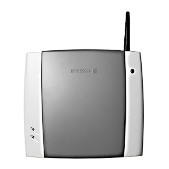
- Page 1 User guide F221m terminal Fixed Cellular Terminal for residential applications...
- Page 2 User guide F221m terminal Fixed Cellular Terminal for residential applications...
-
Page 4: Table Of Contents
Content F221m ... 7 SUPPLIED PARTS... 7 EXTERNAL CONNECTORS AND LIGHT INDICATORS... 8 SIM CARD ... 8 CONNECTIONS ... 9 Installing the FCT as a telephone line ... 9 Preparing your FCT... 10 Installing the FCT on the wall ... 12 Connecting fixed line devices ... - Page 5 Voice mail ... 29 Sending tone signals... 29 Controlling call time (minute minder) ... 29 Emergency number (hot line)... 29 Two voice lines (alternate line service) ... 30 SIM card security ... 31 TROUBLESHOOTING AND FCT INDICATORS 33 Light indicators... 33 Audible tones...
- Page 6 Disposing of the battery ... 52 Moving or storing the FCT ... 52 Accessing the battery compartment ... 52 LIMITED WARRANTY ... 53 Limited Warranty Conditions ... 53 Ericsson Warranty... 53 What Ericsson will do ... 53 Conditions... 53 REGULATORY INFORMATION ... 55 DEFINITIONS... 56...
- Page 7 Ericsson F221m First edition, February 2002 This manual has been published by Ericsson España, S.A. Bilbao Technology Centre, without any warranty. Improvements and changes to this manual needed by typographical errors, inaccuracies of current information, or improvements to programs and/or equipment, may be made by Ericsson España, S.A.
-
Page 8: F221M
The F221m terminal can be easily installed by the end- user following the instructions provided in this guide: • install the terminal • run cabling from the F221m to any location in your house • you will be ready to connect and use standard... -
Page 9: External Connectors And Light Indicators
External connectors and light indicators GSM radio indicator (green led) Power indicator (red led) Telephone interface RS232 port Reset Maintenance connector External connectors and light indicators / SIM card SIM card Your network operator provides you with a SIM (Subscriber Identity Module) card. The SIM card contains information about your telephone number and the services included in your subscription, among other things. -
Page 10: Connections
Connections Warning!: please, before you start any connections refer to section “Safe and Efficient Use” on page 49 in this guide and contact your network operator if you have any questions. Warning!: to get a good FCT protection against electrical discharges and the best audio quality, a good grounding of the power supply is strongly recommended. -
Page 11: Preparing Your Fct
The FCT is also equipped with an RS232 port that enables you to use it as a GSM modem for PC fax, data and SMS services. For this specific configuration, please refer to the FCT Data Reference Manual. See Accessories on page 39. Preparing your FCT You need to follow these steps before you install the FCT on the wall and make all definitive connections. - Page 12 Connect a telephone to the FCT Connect a fixed telephone to the FCT telephone line. Important: you will use this telephone to dial the PIN. Switch on the FCT Connect the power supply. The FCT switches on automatically and the green and red light indicators start flashing.
-
Page 13: Installing The Fct On The Wall
Network search After you have switched on your FCT and entered the PIN, the FCT automatically searches for a network. Note: if the red light is off, there is a problem with the power supply. See “Troubleshooting and FCT indicators” on page 33. When a network is found, the green light switches on or flashes depending on the GSM signal strength. - Page 14 • Do not install the FCT on walls or rooms that contain large amounts of metal, steel or wiring. • Do not expose the FCT to extreme temperatures (near radiators, cooling vents, etc). If you experience poor reception quality, an outdoor antenna may result in improvement.
-
Page 15: Connecting Fixed Line Devices
Warning!: once you have fixed the FCT to the wall and switched it on, check the final status of the red and green lights. If either one is off, there is a problem with the power supply or the GSM signal. See “Troubleshooting and FCT indicators”... - Page 16 Note: it is strongly recommended that the telephone wire is installed indoors in order to avoid lightning damage. Note: the telephone wire should not exceed 600 meters. Larger distances can be achieved by using high quality telephone wire. Checking connections Once the fixed line devices (1 up to 3) have been connected, make the “Ring Back Test”...
-
Page 17: Using Telephones
Using telephones Fixed telephones connected to the FCT telephone line work in the same way as if they were connected to a fixed network. Warning!: you will not be able to make or receive data or fax calls while a speech call is ongoing. Note: you can also benefit from some FCT functionality that you do not usually have on your fixed network. -
Page 18: Using Cli Displays
Using CLI displays Devices that display the incoming number (telephones with display, external displays, etc.) can be directly connected to the FCT line interface in the same way as an ordinary telephone. If your subscription includes the Calling Line Identification (CLI) service and the caller´s network sends the number, the FCT will send the caller´s number towards your CLI display. -
Page 19: Using Fax Machines
Using fax machines The FCT terminal allows the connection of Group 3 analog faxes to the FCT telephone line, in the same way as a telephone. Warning!: the fax communication service has to be registered with your network operator. Otherwise, the network will not allow faxes to be sent or received. -
Page 20: Using Pcs
Using PCs Analog modems connected to the FCT telephone line work in the same way as if they were connected to the fixed line. In this way, you can use your PC standard modem to make data calls (Internet browsing, e-mail, etc.) through the FCT line. To be able to send and receive data calls, you need: –... -
Page 21: Gsm Data Access Type
optionally, to improve the Internet connection, a DNS address and a Proxy address. All these settings will allow you to configure the Dial-up Networking program in your PC in order to establish a GPRS connection. Note: this procedure is similar to the way you configure an Internet connection from a specific ISP (Internet Service Provider). - Page 22 send the CNG tone so that the data call is made automatically by the FCT. Incoming data calls are received in the same way as using the fixed line. Note: if you have a SIM card that does not support separate voice and data numbers, the FCT does not recognize the type of incoming call.
-
Page 23: Advanced Features
Advanced features If a DTMF telephone is connected to the FCT, the following features can be accessed. Changing volume During a call, you can increase or decrease the reception volume level. • Increase volume: dial R# # # # • Decrease volume: dial R**** Diverting calls (call forward) You can divert incoming calls to another phone number when you are unable to answer. - Page 24 To manage diversion of calls … Always When busy When no answer When out of reach Note: if instead of hearing beeps you hear a deep tone, this means that there has been an error in the activation or deactivation. With Function …...
-
Page 25: Restricting Calls (Call Barring)
Restricting calls (call barring) You can restrict certain types of calls that can be made or received. You need a password to turn a call restriction on or off. Initially, this password will be 0000. We recommend you to change it by dialing: **03**OLD_PASSWORD*NEW_PASSWORD* NEW_PASSWORD# The following table shows the restriction alternatives... - Page 26 To manage restriction of calls … All outgoing calls All outgoing international calls All outgoing international calls except your home country All incoming calls All incoming calls when you are abroad With Function … Dial … Activate *33*Password# Deactivate #33*Password# Check status *#33# Activate...
-
Page 27: More Than One Call (Call Wait, Call Hold, Call Transfer, Multiparty Call)
Note: if instead of hearing beeps you hear a deep tone, this means that there has been an error in the activation or deactivation. More than one call (call wait, call hold, call transfer, multiparty call) You can handle more than one call simultaneously. For example, you can put an ongoing call on hold, while you make or answer a second call, and then switch between the two calls. - Page 28 • To ignore the waiting call, take no action. • To continue with the ongoing call and reject the waiting call (give a User Busy indication tone to the waiting call): press R0. • To end the ongoing call and answer the waiting call: press R1.
-
Page 29: Phonebook (Abbreviated Dialing)
Phonebook (abbreviated dialing) You can store telephone numbers in either the SIM card memory or the FCT memory. Up to 99 telephone numbers can be stored in each of them. The following table shows how to manage the phonebook with the 99 memory positions (Pos). Warning!: Pos has to have always two digits. -
Page 30: Voice Mail
Voice mail The answering service of your network allows callers to leave a voice message when you cannot answer your calls. If you have voice mail, you will hear 3 beeps before the dial tone, as soon as you pick up the receiver to make a call. -
Page 31: Two Voice Lines (Alternate Line Service)
To manage the hot line … Activate Deactivate service service and Check status for… phone number service, phone number and timer Note: if instead of hearing beeps you hear a deep tone, this means that there has been an error in the activation or deactivation. -
Page 32: Sim Card Security
To manage alternate line Dial … You will hear… service function … Activate Line 1 **591# 1 beep Activate Line 2 **592# 1 beep Check status Line 1 *#591# Check status Line 2 *#592# Note: if instead of hearing beeps you hear a deep tone, this means that there has been an error in the activation or deactivation. - Page 33 To unblock your SIM card while changing your PIN In order to unblock your SIM card and change the PIN at the same time, please dial the following sequence: **05*PUK*NEW_PIN*NEW_PIN# Advanced features...
-
Page 34: Troubleshooting And Fct Indicators
Troubleshooting and FCT indicators This chapter describes the procedures to identify and, if possible, correct problems that might occur with the FCT or its installation. Some problems require that you call your network operator, but most problems you encounter you can easily correct yourself. - Page 35 Simultaneous flashing Alarm status ENTER PIN ENTER PUK INSERT SIM 1 flash synchronized SIM ERROR Red - - - - - - - - WRONG NETWORK Green - - - - - - - - WRONG SUBNETWORK WRONG SIM FCT LOCKED 2 flashes synchronized - - - - - - - - WRONG XXXCK (where...
- Page 36 If you see… It means… Red light • AC power is ON Green light ON or • The FCT is connected to cellular flashing network and available for use Normal operation mode Both lights • AC Power is OFF • AC Power is ON Red light •...
-
Page 37: Audible Tones
Audible tones The FCT generates audible tones in your telephone set, thus providing the same service characteristics as the one given by the traditional fixed network. The following table describes the nature of the main tones you will get when using the unit. Other standard call progress tones, such as busy tone, number obtainable or ring back tone, are provided directly by the network. -
Page 38: Fct Technical Data
FCT technical data GSM AIR INTERFACE Frequency Bands: Triple-Band E-GSM 900, GSM 1800 and GSM 1900 E-GSM 900 Frequencies: TX 880-915 MHz, RX 925-960 MHz RF power: Maximum 2 W (33 dBm), Power class 4 GSM1800 Frequencies: TX 1710-1785 MHz, RX 1805-1880 MHz RF power: Maximum 1 W (30 dBm),... - Page 39 • Storage Temperature: -40ºC to +85ºC • Storage Humidity: 5 - 95% FCT technical data PRODUCT PRESENTATION Basic Kit: F221m residential, power supply, mains cable, wall-mount bracket, internal antenna, user guide, telephone cable. FCT Size: Height 148 mm, Width 165 mm, Depth 45 mm.
-
Page 40: Accessories
The F200 series terminals benefit from a wide range of accessories, which ensure the best and easiest way to install, serve and maintain the terminals, enhancing their functionality. Only these approved-by-Ericsson accessories will guarantee the quality and performance of the terminals. DA20 Display Adapter... -
Page 41: Dc/Dc Power Adapter
NiMH or NiCd rechargeable AA batteries can also be used with these accessory, but these batteries must be charged using an external charger. Warning!: Ericsson recommends precaution when handling lead-acid batteries, and also special attention over storage and power loss issues. -
Page 42: Annex: Pc Data Configurations
Annex: PC data configurations Windows 98 GPRS set-up Warning!: your PC must have the Dial-up Networking and the TCP/IP protocol installed within the network components. You can check this in ‘Start->Settings->Control Panel’ and double clicking on ‘Network’. If not, these components have to be previously added from your Windows installation disk. - Page 43 4) Click on ‘Finish’. 5) In the ‘Dial-Up Networking’ folder, right-click on the created connection and select ‘Properties’. Annex: PC data configurations 6) In the ‘General’ tab, turn off ‘Use area code and Dialing Properties’. 7) In the ‘Server Types’ tab: –...
- Page 44 8) Push the ‘TCP/IP Settings…’ button. – ‘Server assigned IP address’ must be checked. – ‘Server assigned name server addresses’ must be set if the network operator requires it. If the network operator provides DNS addresses, then these must be added once ‘Specify name server addresses’...
-
Page 45: Windows Nt Gprs Set-Up
You have now installed the GPRS connection. To connect to the GPRS network, follow steps 1 to 3: 1) Go to ‘My Computer’-> Dial-Up Networking’ and open the previously configured connection. 2) Type the user name and password provided by your network operator and verify that the telephone number is *98#. - Page 46 To configure your GPRS connection under a Windows NT PC, follow steps 1 to 8: 1) Go to ‘My Computer’ and double-click ‘Dial-Up Networking’. 2) If there are no previously configured connections, the following wizard will show up. Type a name for the connection and tick ‘I know all about phonebook entries and would rather edit the properties directly’.
- Page 47 5) In the ‘Server’ tab select ‘PPP: Windows NT, Windows 95 Plus, Internet’ from the ‘Dial-up server type’ list. Be sure that ‘TCP/IP’ is the only ticked protocol within the ‘Network protocols’ box. Annex: PC data configurations 6) Push the ‘TCP/IP Settings…’ button. –...
- Page 48 – ‘Use IP header compression’ optional. – ‘Use default gateway on remote network’ turned on. 7) Press ‘OK’ and go to the ‘Security’ tab. Select ‘Accept any authentication including clear text’. 8) Click ‘OK’ all the way to update the configuration. You have now installed the GPRS connection.
- Page 49 2) Type the user name and password provided by your network operator. If a ‘Domain’ field is present, then leave it blank. Annex: PC data configurations 3) Once you are connected, you may use your connection as an ordinary Internet connection. Note: if your network operator has provided you with a Proxy Address, you should configure your Web browser (Internet Explorer, Netscape, etc.)
-
Page 50: Safe And Efficient Use
Only Ericsson Service Points or Certified Service Centres should perform service. • Do not use any accessories other than Ericsson originals with the exception of products approved by Bluetooth Qualification Review Board. Use of... -
Page 51: Radio Frequency Energy
(RF) energy. The system that handles your call when you are using your FCT controls the power level at which your FCT transmits. All Ericsson terminals are designed to not exceed the limits for exposure to RF energy set by national authorities and international health agencies. -
Page 52: Power Supply
Power supply • Ensure that your AC power outlet is adequately grounded, that it is situated near the FCT and it is easily accessible. • Connect the power supply cord only to the AC power outlet that meet the specifications marked on the FCT power supply. -
Page 53: Disposing Of The Battery
• Do not expose the battery to extreme temperatures, never above +60°C. For maximum battery capacity, use the battery in room temperature. • Do not let the metal contacts on the battery touch another metal object. This could short-circuit and damage the battery. -
Page 54: Limited Warranty
• Read the Guidelines for safe and efficient use. • Read all of the terms and conditions of the Ericsson Warranty listed below. • Save your original receipt, which is necessary for warranty repair claims. - Page 55 Product due to normal wear and tear, misuse, including but not limited to use in other than a normal and customary manner, in accordance with Ericsson’s instructions for use and maintenance of the Product, accident, modification or adjustment, acts of God, improper ventilation, or damage resulting from liquid.
-
Page 56: Regulatory Information
Regulatory information Declaration of Conformity We, Ericsson Radio Systems AB of Kistagången 26, Kista S-16480 Stockholm, Sweden declare under our sole responsibility that our product Ericsson type 0130101-BV and in combination with our accessories, to which this declaration relates is in conformity with the appropriate standards 3GPP TS 51.010-1, EN 301... -
Page 57: Definitions
Definitions The following definitions are supplied in order to better understand certain concepts included in this manual: Switch-on: power up the FCT by connecting the AC power supply or a charged battery. Switch-off: power down the FCT by disconnecting the AC power supply or removing the battery. Fixed Line Devices: any analog devices that can be connected to the analog fixed line: •... - Page 59 : : / / / / w w w w w w . . e e r r i i c c s s s s o o n n . . c c o o m m / / w w i i r r e e l l e e s s s s / / p p r r o o d d u u c c t t s s / / f f i i x x e e d d Ericsson España, S. A.
Need help?
Do you have a question about the F221m and is the answer not in the manual?
Questions and answers