Table of Contents
Advertisement
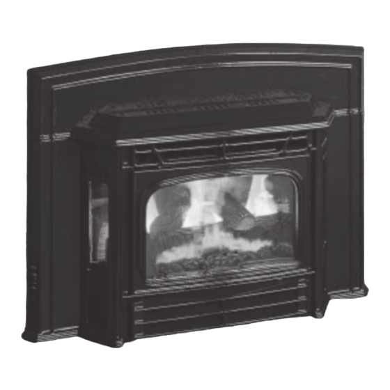
EMERALD Gas Fireplace Insert
WARNING:
If the information in these instructions are not followed exactly,
a fire or explosion may result causing property damage,
personal injury or loss of life.
FOR YOUR SAFETY
Do not store or use gasoline or other flammable vapors and
liquids in the vicinity of this or any other appliance.
Installation and service must be performed by a qualified
installer, service agency or the gas supplier.
Tested by:
908-429a
FPI FIREPLACE PRODUCTS INTERNATIONAL LTD. 6988 Venture St., Delta, BC Canada, V4G 1H4
www.waterfordstoves.com
MODELS:
E61-NG Natural Gas
Installer: Please complete the details on the back cover
and leave this manual with the homeowner.
Homeowner: Please keep these instructions for future reference.
Installation Manual
E61-LP Propane
FOR YOUR SAFETY
What to do if you smell gas:
Do not try to light any appliance
Do not touch any electrical switch:
do not use any phone in your
building.
Immediately call your gas supplier
from a neighbour's phone. Follow
the gas supplier's instructions.
If you cannot reach your gas
supplier, call the fire department.
Owners &
04/21/05
Advertisement
Table of Contents

Related Manuals for Waterford EMERALD E61-LP

Summary of Contents for Waterford EMERALD E61-LP
- Page 1 www.waterfordstoves.com Owners & EMERALD Gas Fireplace Insert Installation Manual MODELS: E61-NG Natural Gas E61-LP Propane WARNING: FOR YOUR SAFETY If the information in these instructions are not followed exactly, What to do if you smell gas: Do not try to light any appliance a fire or explosion may result causing property damage, Do not touch any electrical switch: personal injury or loss of life.
- Page 2 WATERFORD GAS FIREPLACE INSERT TO THE NEW OWNER Congratulations! You are the owner of a state-of-the-art Gas Insert by Waterford Irish Stoves. The Waterford Gas Fireplace Series of hand crafted appliances has been designed to provide you with all the warmth and charm of a fireplace, at the flick of a switch.
-
Page 3: Table Of Contents
TABLE OF CONTENTS WATERFORD GAS FIREPLACE INSERT Page Page SAFETY LABEL OPERATING INSTRUCTIONS Operating Instructions ..........15 Safety Label .............. Lighting Procedure ............15 Shutdown Procedure ........... 15 First Fire ..............15 INSTALLATION REQUIREMENTS Automatic Convection Fan Operation ......15 Normal Operating Sounds of Gas Appliances .... -
Page 4: Safety Label
SAFETY LABEL This is a copy of the label that accompanies each Waterford E61-NG Gas Insert Natural Gas. We have printed a copy of the contents here for your review. The safety label is located on the right side door panel. NOTE: Waterford units are constantly being improved. - Page 5 SAFETY LABEL This is a copy of the label that accompanies each Waterford E61-LP Gas Insert Propane. We have printed a copy of the contents here for your review. The safety label is located on the right side door panel. NOTE: Waterford units are constantly being improved.
-
Page 6: Installation Requirements
INSTALLATION envelope. Never vent to another room or INSTALLATION INTO IMPORTANT: inside a building. Make sure that the vent AFACTORY BUILT SAVE THESE is properly sized and is of adequate height to provide the proper draft. FIREPLACE INSTRUCTIONS 8) Inspect the venting system annually for blockage and any signs of deterioration. -
Page 7: Materials Required
INSTALLATION 5) Pull the vent connector plate through the WARNING: tapered brackets and fasten to the front Electrical Grounding Instructions plate. See page 9. 6) Slide the unit fully into the fireplace and This appliance is equipped with a level. three pronged (grounding) plug for your protection against shock 7) Test gas pressure, page 11. -
Page 8: Gas Connection
INSTALLATION 5) Once the gas has been connected ensure GAS CONNECTION System Data: that the pilot valve is in line with burner. E61 Converted to 27,000 (Natural Gas) The Emerald Insert is factory equipped to burn CAUTION: If the door is removed or Natural Gas, if necessary the unit can be opened for servicing, it must be replaced or 29,000 (Propane) -
Page 9: Flue Liner Installation
INSTALLATION Part # Description nections of liner to inlet and vent col- 948-305 3" Flex - 35 ft. lars. 946-529 Co-linear DV Vertical Termination Cap 10) Attach the top shield to the top front lip of the firebox using 3 screws. Alternate Approved Caps Vertical Termination Cap High Wind Cap... - Page 10 INSTALLATION the new screws (E) supplied with the kit. 9) Unscrew the pilot orifice with the allen key Tighten screws securely. and replace with the LP pilot orifice in the kit. 3) Remove the door by lifting it slightly up and off the front face.
-
Page 11: Reduction To Lower Btu
INSTALLATION 9) Attach the label "This unit has been con- Reduction Kit to Lower verted to..." on top of the Serial # decal over Btu Rating for Emerald the higher Btu information. E61 Gas Insert 10) Check for gas leaks. Natural Gas - Kit #: 260-920 11) Check inlet and outlet pressures. -
Page 12: Valve Description
INSTALLATION 3) To adjust the aeration: use the allen key to 2) Plug the 'quick connect' electrical connec- Valve Description turn the turning gear which will adjust the tion into the junction box. An alternative air shutter. Open the air shutter for a blue wire outlet is provided on the junction box 1) Gas cock knob flame or close it for a yellower flame. -
Page 13: Optional Door Grill Installation
INSTALLATION Front Right Log - Part # 902-020 5) Place the two Small Side Logs beside the OPTIONAL DOOR Front Left Log - Part # 902-021 burner on the firebox floor, as shown in GRILL diagram 4. Rear log - Part # 902-022 Embers - Part # 902-151 (1 bag) 6) Distribute the embers along the front burner Lava - Part # 902-154 (1 bag) -
Page 14: Optional Remote Control Installation
INSTALLATION 3) Install 3 AAA alkaline batteries in transmit- OPTIONAL REMOTE 1) Choose a convenient location on the wall to ter and 4 AA alkaline batteries in install the receiver and the receptacle box CONTROL receiver. Install the receiver and its cover (protection from extreme heat is very im- in the wall. -
Page 15: Operating Instructions
OPERATING INSTRUCTIONS OPERATING 5) Turn the gas control counterclockwise to During the first few fires, a white film "PILOT". Knob cannot be turned from "PI- may develop on the glass front as part INSTRUCTIONS LOT" to "OFF" unless knob is pushed in of the curing process. -
Page 16: Copy Of Lighting Plate Instructions
OPERATING INSTRUCTIONS Gas Control Valve: COPY OF THE As the gas control valve turns ON and OFF, a LIGHTING PLATE INSTRUCTIONS dull clicking sound may be audible, this is normal operation of a gas regulator or valve. Unit Body/Firebox: FOR YOUR SAFETY READ BEFORE LIGHTING Different types and thicknesses of steel will This appliance must be installed in accordance with local codes, if any;... -
Page 17: Log Replacement And Cleaning
MAINTENANCE LOG REPLACEMENT & WARNING: CHILDREN AND ADULTS SHOULD BE ALERTED CLEANING TO THE HAZARDS OF HIGH SUR- FACE TEMPERATURE AND The unit should never be used with broken logs. SHOULD STAY AWAY TO AVOID Turn off the gas valve and allow the unit to cool BURNS OR CLOTHING IGNITION. -
Page 18: Valve Maintenance
MAINTENANCE 7) Carefully lift the burner tray assembly out. VALVE MAINTENANCE IMPORTANT Disconnect power supply 8) Disconnect the 2 TP wires and the 2 TH before servicing If your valve requires maintenance or replace- wires from the valve. ment, use the following instructions: WARNING: Note: Always close off the gas supply before removing the valve. -
Page 19: Parts List
PARTS LIST REPLACEMENT / SPARE PARTS LIST Part # Description 936-243 Gasket - 7/8" w/adhesive Hose Clamp 3-1/16" - 4" 270-013 Front Glass Frame 940-080/P Front Glass 41212 Gasket - 1/4" x 1" Flat w/adhesive 270-014 Side Glass Frame 940-081/P Side Glass Right Mounting Bracket Stove Front Left Mounting Bracket... - Page 20 PARTS LIST REPLACEMENT / SPARE PARTS LIST Part # Description Part # Description 942-031** Decorative Door Grill Front W310770 Fan Speed Control Rheostat (120 V) Screw - 1/4 x 1/2" Flat Head Phillip Zinc Plate 904-656 Blanking Plug for Strain Relief 942-021** Front Door 910-822...
- Page 21 PARTS LIST REPLACEMENT / SPARE PARTS LIST Part # Description 910-190 Piezo Ignitor & Nut 908-672 Control Panel Decal 490-061 Control Panel 270-574/P S.I.T. Valve Assy - NG 270-576/P S.I.T. Valve Assy - LP 910-378 Valve S.I.T. - NG/LP 936-170 Orifice Gasket 910-038 Pilot Assy - S.I.T.
- Page 22 NOTES _____________________________________________________________________________________ ____________________________________________________________________________ ____________________________________________________________________________ ____________________________________________________________________________ _____________________________________________________________________________________ ____________________________________________________________________________ ____________________________________________________________________________ ____________________________________________________________________________ _____________________________________________________________________________________ ____________________________________________________________________________ ____________________________________________________________________________ ____________________________________________________________________________ _____________________________________________________________________________________ ____________________________________________________________________________ ____________________________________________________________________________ ____________________________________________________________________________ _____________________________________________________________________________________ ____________________________________________________________________________ ____________________________________________________________________________ ____________________________________________________________________________ _____________________________________________________________________________________ ____________________________________________________________________________ ____________________________________________________________________________ ____________________________________________________________________________ Waterford E61 Gas Fireplace Insert...
-
Page 23: Warranty
WARRANTY Waterford Fireplace Products are designed with reliability and simplicity in mind. In addition, our internal Quality Assurance Team carefully inspects each unit thoroughly before it leaves our facility. FPI Fireplace Products International Ltd. is pleased to extend this limited lifetime warranty to the original purchaser of a Waterford Product. - Page 24 Waterford fireplace products designed with reliability and simplicity in mind. In addition, our internal Quality Assurance Team carefully inspects each unit thoroughly before it leaves our door. Waterford Irish Stoves is pleased to extend this Limited Lifetime Warranty to the original purchaser of a Waterford Product.
Need help?
Do you have a question about the EMERALD E61-LP and is the answer not in the manual?
Questions and answers