Table of Contents
Advertisement
SG-2000 MANUAL
SG-2000
1.6-30 MHz
150 Watt Output
Multi-Mission
HF SSB
Transceiver
Operations and Programming Manual
Revised: Oct, 1995
Carefully read the "Quick Start"
(yellow card
CAUTION:
packed with your radio) and the "Operating the SG-2000" section
of this manual beginning on Page 41. The SG-2000 is a high
precision electronic device. Taking the time to learn all of its
capabilities will insure maximum performance, reliability and
enjoyment of the unit.
The SGC Building, 13737 S.E. 26th St. Bellevue, WA. 98005 USA
©1995, SGC, Inc.
TEL: (206) 746-6310
FAX: (206) 746-6384
Advertisement
Table of Contents
Troubleshooting

Related Manuals for SGC SG-2000


Summary of Contents for SGC SG-2000
- Page 1 Taking the time to learn all of its capabilities will insure maximum performance, reliability and enjoyment of the unit. The SGC Building, 13737 S.E. 26th St. Bellevue, WA. 98005 USA ©1995, SGC, Inc. TEL: (206) 746-6310 FAX: (206) 746-6384...
-
Page 2: Table Of Contents
Control Head Placement............16 Control Head Wiring..............17 External Speakers...............17 External Accessories ..............18 Radio Licenses ....................19 Station Licenses ................19 Operator Licenses ..............20 The SGC Building, 13737 S.E. 26th St. Bellevue, WA. 98005 USA ©1995, SGC, Inc. TEL: (206) 746-6310 FAX: (206) 746-6384... - Page 3 SG-2000 MANUAL The SGC Building, 13737 S.E. 26th St. Bellevue, WA. 98005 USA ©1995, SGC, Inc. TEL: (206) 746-6310 FAX: (206) 746-6384...
- Page 4 Front Panel Controls..............52 13.3 Primary Keyboard Functions ...........52 13.4 Shift Functions................57 13.5 Program Functions..............59 13.6 Operating Session ..............59 13.7 Channel..................60 13.8 Frequency..................61 The SGC Building, 13737 S.E. 26th St. Bellevue, WA. 98005 USA ©1995, SGC, Inc. TEL: (206) 746-6310 FAX: (206) 746-6384...
- Page 5 18.5 SG-2000 Connections to ALE Controller ........104 19.0 Accessories 106 19.1 Exsel-100 Selective Calling System..........106 19.2 Telerex™ ARQ/FEC/SELFEC System ........107 The SGC Building, 13737 S.E. 26th St. Bellevue, WA. 98005 USA ©1995, SGC, Inc. TEL: (206) 746-6310 FAX: (206) 746-6384...
- Page 6 SG-2000 MANUAL 20.0 Answers to Frequently Asked Questions.............108 The SGC Building, 13737 S.E. 26th St. Bellevue, WA. 98005 USA ©1995, SGC, Inc. TEL: (206) 746-6310 FAX: (206) 746-6384...
- Page 7 Head CPU and Main CPU Testing Procedures .....171 23.5 Final Assembly Testing Procedures ........178 24.0 Schematic Reference Section ................180 INDEX ........................210 Appendix A, Frequency List ..................A-1 The SGC Building, 13737 S.E. 26th St. Bellevue, WA. 98005 USA ©1995, SGC, Inc. TEL: (206) 746-6310 FAX: (206) 746-6384...
-
Page 8: General Description And Specifications
Fast attack slow release in Voice mode. Extremely fast attack fast release in telex and ALE modes. Keypad 21 push-buttons include power, up/down, all functions, and numeric entry The SGC Building, 13737 S.E. 26th St. Bellevue, WA. 98005 USA ©1995, SGC, Inc. TEL: (206) 746-6310 FAX: (206) 746-6384... -
Page 9: Power Requirements
Image and IF rejection +90 dB Audio output 4W with less than 10% distortion Audio distortion Less than 5% at 3W The SGC Building, 13737 S.E. 26th St. Bellevue, WA. 98005 USA ©1995, SGC, Inc. TEL: (206) 746-6310 FAX: (206) 746-6384... -
Page 10: Data Communications
Minimum required 100 mV RMS, 2V RMS maximum AFSK output level 240mV RMS at .5µV, maximum 1V RMS Computer Control of SG-2000 Input/Output RS 232 The SGC Building, 13737 S.E. 26th St. Bellevue, WA. 98005 USA ©1995, SGC, Inc. TEL: (206) 746-6310 FAX: (206) 746-6384... - Page 11 SG-2000 for DOS (Supplied with C language source code) System software DOS Ver. 3.0 or greater for IBM and compatibles (user supplied) The SGC Building, 13737 S.E. 26th St. Bellevue, WA. 98005 USA ©1995, SGC, Inc. TEL: (206) 746-6310 FAX: (206) 746-6384...
-
Page 12: Multiple Control Head Specifications
• Time of day or date display • Radio on/off timer • Intercom with all stations or private channel select The SGC Building, 13737 S.E. 26th St. Bellevue, WA. 98005 USA ©1995, SGC, Inc. TEL: (206) 746-6310 FAX: (206) 746-6384... -
Page 13: External Accessories
• Special Software options: Hong Kong, France (and Territories), Oil Platform Notes: * CFT8DK SG-2000 (1.8 to 26 MHz international radio marine bands) For international marine bands The SGC Building, 13737 S.E. 26th St. Bellevue, WA. 98005 USA ©1995, SGC, Inc. TEL: (206) 746-6310 FAX: (206) 746-6384... - Page 14 SG-2000 MANUAL Under ambient temperature and normal load conditions The SGC Building, 13737 S.E. 26th St. Bellevue, WA. 98005 USA ©1995, SGC, Inc. TEL: (206) 746-6310 FAX: (206) 746-6384...
-
Page 15: 2.0 Unpacking
The standard packaging for an SG-2000, the cardboard box and packing materials, should be retained for future use should the radio need to be shipped elsewhere. The SGC Building, 13737 S.E. 26th St. Bellevue, WA. 98005 USA ©1995, SGC, Inc. - Page 16 LCD may be removed with Plexiglas™ cleaner such as is used to clean aircraft windows. The SG-2000 should be closely inspected upon arrival. As the units leave the SGC factory, they are in perfect operating condition. Should you notice any bent sheet metal, or flecks of paint in the shipping box, you may assume that the radio has taken a hard shock somewhere in shipping.
-
Page 17: History Of The Sg-2000
This was done after a careful study of emerging HF radio technology in the military and government sector and with an eye to providing the users of SGC equipment with the highest level of flexibility, not only today but in the future as well. - Page 18 SG-2000 in appearance. In 1994, SGC introduced a SlimPak version. The SlimPak has all the features of the SG- 2000 and uses the same control head; yet the main unit measures a full 1 inch less in height, enabling placement in much tighter quarters.
-
Page 19: About The Sg-2000
For AM, the SG-2000 provides one of the few "true AM" detectors available today. This provides for extremely clear reception and excellent The SGC Building, 13737 S.E. 26th St. Bellevue, WA. 98005 USA ©1995, SGC, Inc. - Page 20 SG-2000 MANUAL capture of signals in all modes. The SGC Building, 13737 S.E. 26th St. Bellevue, WA. 98005 USA ©1995, SGC, Inc. TEL: (206) 746-6310 FAX: (206) 746-6384...
-
Page 21: Transmitter Signal Path
In the control heads, the audio signal is further amplified and processed. A syllabic squelch circuit (which was pioneered by SGC in 1976) is used to turn off the noise coming out of the speaker in the event that a signal is not being received. -
Page 22: Control Circuits
This means that the control head may be placed as much as 50 meters away from the radio. Although not supported by SGC, many users of the control heads have reported success at longer distances. As with all SGC specifications, 50 meters is a conservative number. -
Page 23: Control Heads
10-conductor control cable between our radios and remote heads rather than a fiber optic cable is one example. SGC has learned that while fiber optics are an excellent material, they are not easily reparable in the middle of the desert or ocean. - Page 24 In addition, just to the right of the "U" bracket is an RS-232 connector for computer control of the SG-2000 radio, as explained later in this manual. The SGC Building, 13737 S.E. 26th St. Bellevue, WA. 98005 USA ©1995, SGC, Inc.
-
Page 25: 5.0 Sgc Family Of Control Heads
They include the basic version, the aircraft version, the Exsel version and the remote mobile head with ADSP™ noise reduction. Please contact SGC for information on any of these optional heads. PowerTalk™ Another optional control head is our newly released PowerTalk™ head. The PowerTalk™... -
Page 26: 6.0 Sg-2000 Software And Accessories
Effective September 1, 1992, a special edition of the SG-2000 became available to users of the SG-2000 in Hong Kong. Certain radio programming features are deleted in order to meet Type Approval requirements of Hong Kong's G.P.O. The SGC Building, 13737 S.E. 26th St. Bellevue, WA. 98005 USA ©1995, SGC, Inc. TEL: (206) 746-6310... -
Page 27: 7.0 Planning For Installation
If your mobile installation is larger, as in a bus or large recreational vehicle, you may wish to have one control head in the rear area and another control head in the vehicle The SGC Building, 13737 S.E. 26th St. Bellevue, WA. 98005 USA ©1995, SGC, Inc. -
Page 28: Control Head Wiring
SG-2000 is attached to the radio. This is because a separate speaker audio line is run from the attached control head (where the audio amplifier is The SGC Building, 13737 S.E. 26th St. Bellevue, WA. 98005 USA ©1995, SGC, Inc. TEL: (206) 746-6310... -
Page 29: External Accessories
(TNC) for amateur use, a commercial standard SITOR modem, such as the SGC TELEREX™ system, or an ALE controller such as the SGC HardLink™ System, provision for the mounting and operation of these items should be made at the time of installation. -
Page 30: 8.0 Radio Licenses
On the license application, where "Type Acceptance Identifier" is requested please fill in the following: CFT8DKSG2000 The SGC Building, 13737 S.E. 26th St. Bellevue, WA. 98005 USA ©1995, SGC, Inc. TEL: (206) 746-6310 FAX: (206) 746-6384... -
Page 31: Operator Licenses
Information about becoming a ham radio operator in the U.S. is available by calling the National Amateur Radio Association, NARA, which maintains a toll-free (800) telephone number. The SGC Building, 13737 S.E. 26th St. Bellevue, WA. 98005 USA ©1995, SGC, Inc. TEL: (206) 746-6310... -
Page 32: 9.0 Installation
You will see the connectors when you loosen the Philips head screws which hold the protective sheet metal cover over the rear panel connectors and remove the cover. The SGC Building, 13737 S.E. 26th St. Bellevue, WA. 98005 USA ©1995, SGC, Inc. TEL: (206) 746-6310... -
Page 33: External Coupler Installation
Do not connect the Red/White wire from the SG-230/SG-235 as this wire is used to control coupler functions. See SG-230/SG-235 manuals for details on coupler control options via this wire. The SGC Building, 13737 S.E. 26th St. Bellevue, WA. 98005 USA ©1995, SGC, Inc. TEL: (206) 746-6310... -
Page 34: External Modem, Weatherfax And High Seas Direct
ARQ data transmission mode, then continuous duty ratings are required. All SGC equipment is conservatively rated. We use commercial service ratings for all of our equipment and make continuous service available upon request. -
Page 35: Rack Mount Kit Installation (Part No. 52-90)
120 watts continuous. Maintain an unrestricted air flow area of at least 1 inch around all surfaces of the radio. SGC Part Number 52-90 (Rack mount kit for SG-2000) has fans built in and is also suited for continuous duty operation. Field installation instructions for the rack mount follow. -
Page 36: Installation Procedure
"-" set radio back down (if necessary). Secure radio to bottom cover. Use four #6 black Philips Head screws removed in step #2. The SGC Building, 13737 S.E. 26th St. Bellevue, WA. 98005 USA ©1995, SGC, Inc. TEL: (206) 746-6310... - Page 37 Attach control head/front panel assembly to tray assembly using 7 each #4 lock washers and #4 nuts (supplied attached The SGC Building, 13737 S.E. 26th St. Bellevue, WA. 98005 USA ©1995, SGC, Inc. TEL: (206) 746-6310 FAX: (206) 746-6384...
- Page 38 SG-2000 MANUAL to front panel) The SGC Building, 13737 S.E. 26th St. Bellevue, WA. 98005 USA ©1995, SGC, Inc. TEL: (206) 746-6310 FAX: (206) 746-6384...
-
Page 39: Control Head Installations
SG-2000 and remove the top cover. Two screws are located on each side of the radio and two screws are located on the top The SGC Building, 13737 S.E. 26th St. Bellevue, WA. 98005 USA ©1995, SGC, Inc. - Page 40 Phillips head screws. Cable clamp on left side of rear panel is not used with external control head. Installation of the remote control head is now complete. The SGC Building, 13737 S.E. 26th St. Bellevue, WA. 98005 USA ©1995, SGC, Inc. TEL: (206) 746-6310...
-
Page 41: Additional Control Heads (Part No. 04-11)
REAR PANEL CONNECTION FOR ADDITIONAL CONTROL HEADS SG-2000 Rear J-503 Junction Box for Additional Control Heads Single control head The SGC Building, 13737 S.E. 26th St. Bellevue, WA. 98005 USA ©1995, SGC, Inc. TEL: (206) 746-6310 FAX: (206) 746-6384... -
Page 42: Remote Head Cable Extension
Carefully unplug the existing cable assembly from the control head and radio and replace it with the desired length. While we recommend that you use the control head wiring supplied by SGC, you may use any other 10-conductor shielded wiring. Remember, however, that the length of the cable run to a remote head is partly determined by the quality of wiring used. -
Page 43: 10.0 Power Supplies
The longer the distance between a power supply and a radio, the greater the voltage drop will be. SGC recommends placing a power supply no more than 25 feet from a radio. There are two reasons for this: First. -
Page 44: Ac Power Supplies
SGC does not generally recommend switching type power supplies in either a mobile or a base station installation for these two reasons: first, switching power supplies easily generate noise from the switching circuitry;... -
Page 45: Mobile Power Supplies
First, HF takes a lot of power on transmit. While you can use a single battery to power both the vehicle and the radio, SGC recommends the installation of an additional battery in all cases where this is practical. The reason for this is that the output voltage from a battery drops as the load increases. -
Page 46: Solar-Powered Chargers
It should operate over a wide range of loads and should continue to provide trickle charging to keep the battery system charged to its fullest between operating sessions. The SGC Building, 13737 S.E. 26th St. Bellevue, WA. 98005 USA ©1995, SGC, Inc. TEL: (206) 746-6310... -
Page 47: 11.0 Antenna Systems
Antenna length is not the only consideration. Another important factor is antenna wire size The SGC Building, 13737 S.E. 26th St. Bellevue, WA. 98005 USA ©1995, SGC, Inc. TEL: (206) 746-6310 FAX: (206) 746-6384... -
Page 48: Antenna Wire Size
— is lowered as the horizontal antenna moves up from ground level. The angle approaches its minimum one wavelength or more above ground. The SGC Building, 13737 S.E. 26th St. Bellevue, WA. 98005 USA ©1995, SGC, Inc. -
Page 49: Near Vertical Incidence Skywave
(dipole lobes are perpendicular to the wire axis), or beam antennas. The SGC Building, 13737 S.E. 26th St. Bellevue, WA. 98005 USA ©1995, SGC, Inc. TEL: (206) 746-6310... -
Page 50: Antenna Feed Lines
Medium Wave transmitters — then the best way to get RF from point "A" to point "B" is via 50 ohm impedance coaxial cable. The SGC Building, 13737 S.E. 26th St. Bellevue, WA. 98005 USA ©1995, SGC, Inc. TEL: (206) 746-6310... -
Page 51: Antenna Couplers
HF radio controllers. So SGC began to build computer controlled antenna couplers including the SG-230 and SG-235 Smartuner™ couplers. SGC began building the servo-motor type automatic couplers in 1975 so the transition to a computerized coupler with extremely fast retune times was a logical development. -
Page 52: Qms Recommended For Mobile Use
1.8 to 30 MHz. SGC is the only manufacturer to add the good attributes of a 108" whip (which performs well at the 20 MHz range and above) with the high performance of a helical antenna that performs well at the lower frequencies. -
Page 53: Unconventional Mobile Antennas
QMS mounts without drilling any holes in your vehicle. That's a major advantage at vehicle trade-in time. So, if you're planning to use HF while mobile, SGC's QMS system is the best solution you'll find. Contact your SGC dealer or call SGC direct. - Page 54 Other antennas which may be used successfully on HF may be found in the SG-230 Smartuner manual. We highly recommend the use of one of our Smartuners™ for all HF installations where practical. The SGC Building, 13737 S.E. 26th St. Bellevue, WA. 98005 USA ©1995, SGC, Inc. TEL: (206) 746-6310...
-
Page 55: Operating The Sg-2000
With a ham radio type memory, they would have to know where, among the typical 100 memories, were programmed the frequencies for KMI. The SGC Building, 13737 S.E. 26th St. Bellevue, WA. 98005 USA ©1995, SGC, Inc. TEL: (206) 746-6310... - Page 56 This means that when you wish to delete a channel, you must handle deletion from the channel display, not the frequency display. The SGC Building, 13737 S.E. 26th St. Bellevue, WA. 98005 USA ©1995, SGC, Inc.
-
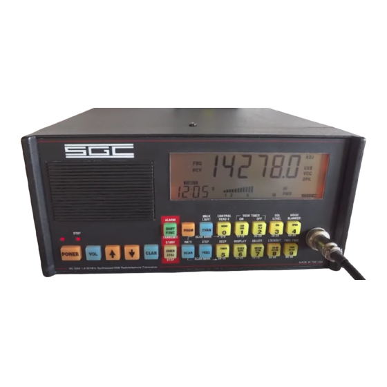
Page 57: Front Panel
The front panel of the control head of the SG-2000 radio is shown in the picture below. The next section, Key Functions, refers to the keys on this picture. The SGC Building, 13737 S.E. 26th St. Bellevue, WA. 98005 USA ©1995, SGC, Inc. -
Page 58: 12.3 Push-Button Functions
PRGM , FREQ enter frequency, PRGM NOTE: When a programming sequence begins with PRGM, you must press PRGM at the end of The SGC Building, 13737 S.E. 26th St. Bellevue, WA. 98005 USA ©1995, SGC, Inc. TEL: (206) 746-6310 FAX: (206) 746-6384... -
Page 59: Channel Functions
Voice - Telex Filter Switch Press Observe front panel display changes Squelch On / Off Press Observe front panel display changes and The SGC Building, 13737 S.E. 26th St. Bellevue, WA. 98005 USA ©1995, SGC, Inc. TEL: (206) 746-6310 FAX: (206) 746-6384... - Page 60 Beep each key stroke Press SHIFT/FUNC Alternate Time - Date Press SHIFT/FUNC SWR Forward - Reverse Press SHIFT/FUNC SCAN FUNCTIONS The SGC Building, 13737 S.E. 26th St. Bellevue, WA. 98005 USA ©1995, SGC, Inc. TEL: (206) 746-6310 FAX: (206) 746-6384...
-
Page 61: Channel Scan
Define User Channel Duplex Press PRGM CHAN enter channel #, FREQ enter RCV frequency, FREQ set parameters, FREQ enter TX frequency, PRGM The SGC Building, 13737 S.E. 26th St. Bellevue, WA. 98005 USA ©1995, SGC, Inc. TEL: (206) 746-6310 FAX: (206) 746-6384... -
Page 62: Sample Entries
If you hold the down arrow, you will keep moving down the band. You can change the size of the frequency step easily. See Frequency Functions. The SGC Building, 13737 S.E. 26th St. Bellevue, WA. 98005 USA ©1995, SGC, Inc. TEL: (206) 746-6310... - Page 63 SG-2000 MANUAL The SGC Building, 13737 S.E. 26th St. Bellevue, WA. 98005 USA ©1995, SGC, Inc. TEL: (206) 746-6310 FAX: (206) 746-6384...
-
Page 64: Tour Of The Sg-2000
403. It also says that the radio is in the receive mode, as indicated by the RCV indicator. The SGC Building, 13737 S.E. 26th St. Bellevue, WA. 98005 USA ©1995, SGC, Inc. TEL: (206) 746-6310... - Page 65 SWR. (A good automatic antenna coupler, such as the SG- 230 or SG-235 Smartuner™, will virtually eliminate SWR on antenna feed lines and increase transmitter efficiency.) The SGC Building, 13737 S.E. 26th St. Bellevue, WA. 98005 USA ©1995, SGC, Inc. TEL: (206) 746-6310...
- Page 66 The SGC Building, 13737 S.E. 26th St. Bellevue, WA. 98005 USA ©1995, SGC, Inc. TEL: (206) 746-6310 FAX: (206) 746-6384...
-
Page 67: Front Panel Controls
CHAN button enables the user to input a preprogrammed channel of their choosing . The SGC Building, 13737 S.E. 26th St. Bellevue, WA. 98005 USA ©1995, SGC, Inc. TEL: (206) 746-6310 FAX: (206) 746-6384... - Page 68 Government or special applications only. In the amateur bands, frequencies on 40 meters (the 7 MHz band) and lower have traditionally employed lower sideband. The SGC Building, 13737 S.E. 26th St. Bellevue, WA. 98005 USA ©1995, SGC, Inc. TEL: (206) 746-6310...
- Page 69 SG-2000. When this pad is in the ON position, the SG-2000 reduces it's sen- sitivity to overcome unwanted RF noise, interference signals The SGC Building, 13737 S.E. 26th St. Bellevue, WA. 98005 USA ©1995, SGC, Inc. TEL: (206) 746-6310...
- Page 70 U.S. Bureau of Standards time stations, WWV and WWVH. These may be found 24 hours a The SGC Building, 13737 S.E. 26th St. Bellevue, WA. 98005 USA ©1995, SGC, Inc. TEL: (206) 746-6310...
- Page 71 2.5, 5, 10, 15, and 20 MHz providing time of day, storm warnings and navigation aid updates including the status of GPS satellites. The SGC Building, 13737 S.E. 26th St. Bellevue, WA. 98005 USA ©1995, SGC, Inc. TEL: (206) 746-6310...
- Page 72 If the squelch is activated in scan, the unit will continue scanning until activity breaks the squelch. The unit will then pause for 5 The SGC Building, 13737 S.E. 26th St. Bellevue, WA. 98005 USA ©1995, SGC, Inc. TEL: (206) 746-6310...
-
Page 73: Shift Functions
This function allows you to set a squelch level by using the Up SQL Level The SGC Building, 13737 S.E. 26th St. Bellevue, WA. 98005 USA ©1995, SGC, Inc. TEL: (206) 746-6310... - Page 74 Hz), .5 (500 Hz), 1, 3 and 5 KHz. If you are operating in ham bands (and especially when using CW), the 100 Hz (.1 KHz) The SGC Building, 13737 S.E. 26th St. Bellevue, WA. 98005 USA ©1995, SGC, Inc.
-
Page 75: Program Functions
13.6 Operating Session This section will give you practical key entry sequences which will make operating the The SGC Building, 13737 S.E. 26th St. Bellevue, WA. 98005 USA ©1995, SGC, Inc. TEL: (206) 746-6310 FAX: (206) 746-6384... - Page 76 The temperature of the onboard crystal oven can be maintained ready for power-up if the oven switch (on the rear panel of the SGC-2000) supplies 12 VDC power. The red stand- by light will remain on. (As you will recall from the introduction to the radio, the onboard frequency standard uses a highly stable crystal oscillator.)
-
Page 77: Channel
There are two ways to change the operating frequency of an SG-2000. For large frequency changes, you may use the direct entry method. For small The SGC Building, 13737 S.E. 26th St. Bellevue, WA. 98005 USA ©1995, SGC, Inc. TEL: (206) 746-6310... - Page 78 Press “PRGM” to alert the memory that new information is coming. Press “FREQ” to specify that frequency numbers will follow. The SGC Building, 13737 S.E. 26th St. Bellevue, WA. 98005 USA ©1995, SGC, Inc. TEL: (206) 746-6310...
- Page 79 Alternatively, it may be used to adjust the tone of a CW station to a desired frequency. The sequence to use the Clarifier is: Press “CLAR.” Press the “Up” or “Down” arrows. The SGC Building, 13737 S.E. 26th St. Bellevue, WA. 98005 USA ©1995, SGC, Inc. TEL: (206) 746-6310 FAX: (206) 746-6384...
-
Page 80: Programming
Enter the desired channel number (09.) Press the “FREQ” button. Enter the desired frequency including one digit right of the decimal point. (147351.) The SGC Building, 13737 S.E. 26th St. Bellevue, WA. 98005 USA ©1995, SGC, Inc. TEL: (206) 746-6310 FAX: (206) 746-6384... -
Page 81: Scanning Functions
The SG-2000 will scan both frequencies and channels. You can scan from 2 to 30 MHz continuously in 100 Hz steps. Or, you may scan just a few of the hundreds of channels. The SGC Building, 13737 S.E. 26th St. Bellevue, WA. 98005 USA ©1995, SGC, Inc. TEL: (206) 746-6310... - Page 82 To allow the pause on detection, press the squelch by pressing “3” or “SQL.” To stop the scan, simply press the “SCAN” button. The SGC Building, 13737 S.E. 26th St. Bellevue, WA. 98005 USA ©1995, SGC, Inc. TEL: (206) 746-6310...
- Page 83 3.9 MHz and would then scan only from 4.00 MHz to 3.900 MHz after it reached that range.) The SGC Building, 13737 S.E. 26th St. Bellevue, WA. 98005 USA ©1995, SGC, Inc.
- Page 84 VOC or TLX mode respectively by engaging the “2” or “VOC/TLX” button. To stop the scan, simply press the “SCAN” button. The SGC Building, 13737 S.E. 26th St. Bellevue, WA. 98005 USA ©1995, SGC, Inc. TEL: (206) 746-6310...
-
Page 85: Changing Frequency Or Channel Scan Rates
1 step per second 2 steps per second 5 steps per second This function will automatically time out after four seconds. The SGC Building, 13737 S.E. 26th St. Bellevue, WA. 98005 USA ©1995, SGC, Inc. TEL: (206) 746-6310 FAX: (206) 746-6384... -
Page 86: Additional Functions
The function will automatically time out after four seconds. 13.12 Additional Functions Timer To turn timer on and off: Press “5” or “TIMER” The SGC Building, 13737 S.E. 26th St. Bellevue, WA. 98005 USA ©1995, SGC, Inc. TEL: (206) 746-6310 FAX: (206) 746-6384... - Page 87 Type in desired channel number Press “PRGM.” Clock / Date To toggle between time of day (24 hour format), and date: The SGC Building, 13737 S.E. 26th St. Bellevue, WA. 98005 USA ©1995, SGC, Inc. TEL: (206) 746-6310 FAX: (206) 746-6384...
- Page 88 SG-2000 MANUAL Press “CLOCK/DATE.” The SGC Building, 13737 S.E. 26th St. Bellevue, WA. 98005 USA ©1995, SGC, Inc. TEL: (206) 746-6310 FAX: (206) 746-6384...
- Page 89 Press the "7" or "INTCM/XCV" keys Depress a number key 1 to 8 for any specific control head or 0 for all control heads. The SGC Building, 13737 S.E. 26th St. Bellevue, WA. 98005 USA ©1995, SGC, Inc. TEL: (206) 746-6310...
- Page 90 Delete To delete last entry made: While in programming mode, press the “SHIFT/FUNC” button. Press the “7” or “INTCM/XCV” button. The SGC Building, 13737 S.E. 26th St. Bellevue, WA. 98005 USA ©1995, SGC, Inc. TEL: (206) 746-6310 FAX: (206) 746-6384...
- Page 91 Use the following sequence to enable transmit capability on all direct entry frequencies plus frequencies which are contained in channel memories: “SHIFT/FUNC”, “8”, “7”, “CHAN” The SGC Building, 13737 S.E. 26th St. Bellevue, WA. 98005 USA ©1995, SGC, Inc. TEL: (206) 746-6310...
- Page 92 To temporarily store settings, press the “PRGM” then “SHIFT/FUNC” buttons. To recover these temporary settings, press “SHIFT/FUNC” then “PRGM.” The SGC Building, 13737 S.E. 26th St. Bellevue, WA. 98005 USA ©1995, SGC, Inc. TEL: (206) 746-6310...
-
Page 93: 14.0 Mobile Installation
Here, displacement would be 1/2 inch or less. This means a calculation of: .5 inch times 2 = a vibration factor of 1. The SGC Building, 13737 S.E. 26th St. Bellevue, WA. 98005 USA ©1995, SGC, Inc. TEL: (206) 746-6310... -
Page 94: Mobile Grounds
#6 gauge stranded wire and that the ground of the battery be cleaned periodically to make as good a connection as possible. Wire runs will cause loss. SGC does not recommend any 12 VDC run of more than 25 feet. - Page 95 The SGC Building, 13737 S.E. 26th St. Bellevue, WA. 98005 USA ©1995, SGC, Inc. TEL: (206) 746-6310...
-
Page 96: Vehicular Noise Sources
The second step in the “cure” involves the use of what we call “Vitamin C,” electrical capacitance. Applying a capacitor at the right location will The SGC Building, 13737 S.E. 26th St. Bellevue, WA. 98005 USA ©1995, SGC, Inc. TEL: (206) 746-6310... - Page 97 Wheel static may be eliminated with brushes, and accessory noise may be isolated by turning on and off items such as heater fans and air con- ditioners. The SGC Building, 13737 S.E. 26th St. Bellevue, WA. 98005 USA ©1995, SGC, Inc. TEL: (206) 746-6310...
-
Page 98: 15.0 Marine Installation
The most common configuration of the SG-2000 in the marine environment is use of a standard mounting tray (SGC Part Number 52-46) and the remote head kit (SGC Part Number 04-12). With the control head detached from the body of the radio, the operating position may be made much more compact. - Page 99 SG-2000 MANUAL SGC does not endorse the use of artificial ground plates as a replacement for an adequate bonding system. While such plates, generally made out of a porous zinc alloy, provide some grounding, they are also subject to corrosion and marine growth which reduces their efficiency.
- Page 100 SG-2000 MANUAL The SGC Building, 13737 S.E. 26th St. Bellevue, WA. 98005 USA ©1995, SGC, Inc. TEL: (206) 746-6310 FAX: (206) 746-6384...
-
Page 101: Marine Antennas
Keep lower insulator as close to deck as possible - just above tensioner. SGC recommends that the top insulator be placed 4 feet down from the top of the mast to reduce the risk of lightning striking the radio antenna. In addition, we recommend... - Page 102 (Provides connection from Modem to SG-2000) Item Common PTT out Mic Out Audio In not used Ground (PTT and radio) The SGC Building, 13737 S.E. 26th St. Bellevue, WA. 98005 USA ©1995, SGC, Inc. TEL: (206) 746-6310 FAX: (206) 746-6384...
- Page 103 J301 Rear Panel Conn Item Item <--connect--> TX Out <--connect--> Audio In RX In <--connect--> Audio Out Ground <--connect--> Ground The SGC Building, 13737 S.E. 26th St. Bellevue, WA. 98005 USA ©1995, SGC, Inc. TEL: (206) 746-6310 FAX: (206) 746-6384...
-
Page 104: 16.0 Remote Control
Third is via computer network and auto-answer devices. The first method does not require any additional equipment. The second two require the addition of the SG-2000 RS-232 option (SGC Part Number 52-34) SGC does not warrant the remote installation of any unit in configurations which exceed the 50 meter limit of the RS-422 standard used by the local area network between control heads and the radio. -
Page 105: Short Haul Modems/Auto-Answer Devices
SGC and its dealers do not provide system integration with complex networks. Such services may be undertaken from time to time by either SGC or its dealers, but arrangements to do so are always separate agreements from supply of radio equipment. -
Page 106: Auto-Answer Devices
If this is the case, please refer to the section of the SG-2000 manual which covers The SGC Building, 13737 S.E. 26th St. Bellevue, WA. 98005 USA ©1995, SGC, Inc. - Page 107 SG-2000 MANUAL details of ALE (adaptive HF controllers) and serial port communications. The SGC Building, 13737 S.E. 26th St. Bellevue, WA. 98005 USA ©1995, SGC, Inc. TEL: (206) 746-6310 FAX: (206) 746-6384...
-
Page 108: 17.0 External Software
RS-232 connection enables this to be a smooth and user friendly process. The SGC RS-232 software system provides for direct computer control of the popular SG-2000 all band solid state HF transceiver. Because of its advanced design, the SG-2000 may be configured to support any combination of up to eight computers and control heads. -
Page 109: Software Installation
This section outlines system requirements, equipment setup, software instal- lation, and troubleshooting information. SGC software is shipped on a 3 .5" disk although 5.25" is available upon request. You may install the software on a hard disk or you may run it directly from the product disk. - Page 110 This software is for use on only one computer. One back up copy is permitted. Title to the medium is transferred to the customer but SGC, Inc. retains all title to the software. Customer is expressly prohibited from disassembly of the The SGC Building, 13737 S.E.
- Page 111 SG-2000 MANUAL software without written authorization from SGC. The SGC Building, 13737 S.E. 26th St. Bellevue, WA. 98005 USA ©1995, SGC, Inc. TEL: (206) 746-6310 FAX: (206) 746-6384...
- Page 112 All copyright notices shall be retained on all copies of the software. SGC, Inc shall be absolved from all liability resulting from the use of this software. SGC's sole liability will be for free replacement of damaged software.
-
Page 113: Main Menu Display
Active audio filter ___________________Middle right side Active Sideband _____________________Middle right side Meter selection ______________________Above left menu Power setting _______________________Above right menu The SGC Building, 13737 S.E. 26th St. Bellevue, WA. 98005 USA ©1995, SGC, Inc. TEL: (206) 746-6310 FAX: (206) 746-6384... -
Page 114: Main Menu Operations
To stop scanning, simply press the space bar. Change Mode Press "E" and you will toggle through various modes of operation. The SGC Building, 13737 S.E. 26th St. Bellevue, WA. 98005 USA ©1995, SGC, Inc. TEL: (206) 746-6310 FAX: (206) 746-6384... - Page 115 [A] USB/LSB [E]TIME / DATE [B] NOISE BLANKER [F]VOC / TLX [C] POWER METER MODE TIMER [D] POWER LEVEL QUIT The SGC Building, 13737 S.E. 26th St. Bellevue, WA. 98005 USA ©1995, SGC, Inc. TEL: (206) 746-6310 FAX: (206) 746-6384...
-
Page 116: Menu 2 Operations
Timer This selection enables you to activate or deactivate the timer. Quit This selection allows you to quit the program. The SGC Building, 13737 S.E. 26th St. Bellevue, WA. 98005 USA ©1995, SGC, Inc. TEL: (206) 746-6310 FAX: (206) 746-6384... -
Page 117: Programming Functions
"wake up" frequency and mode: Enter on Frequency MODE RX FREQUENCY 0.0 AUDIO FILTER TX FREQUENCY 0.0 SIDE BAND ATTENUATOR The SGC Building, 13737 S.E. 26th St. Bellevue, WA. 98005 USA ©1995, SGC, Inc. TEL: (206) 746-6310 FAX: (206) 746-6384... - Page 118 Program the time in the following format: hr : min : sec. Date: Program the date in the following format month-day-year, i.e., 01-01-92. The SGC Building, 13737 S.E. 26th St. Bellevue, WA. 98005 USA ©1995, SGC, Inc. TEL: (206) 746-6310 FAX: (206) 746-6384...
-
Page 119: Pc Cable Assembly
9-pin RS-232 socket on the back of the SG-2000 radio and a 25-pin female connector to be connected to the 25-pin RS-232 plug of the computer's COM port. The SGC Building, 13737 S.E. 26th St. Bellevue, WA. 98005 USA ©1995, SGC, Inc. TEL: (206) 746-6310... - Page 120 SG-2000 MANUAL This cable assembly is not supplied by SGC. This information is furnished solely for customers to successfully build their own cables. However, a standard modem cable with a 9-pin male end and either a 9- or 25-pin female end (available both ways) is normally set up this way and will function efficiently if these three wires are verified to be connected as shown.
-
Page 121: Ale And Adaptive Controllers
N O T I C E : The SG-2000 radio as described in this manual is not a controlled export item. ALE controllers provided by SGC or other vendors which incorporate link protection systems are export controlled technology. THE EXPORT OF THESE ALE CONTROLLERS REQUIRES A STATE DEPARTMENT EXPORT LICENSE. -
Page 122: Sg-2000 Serial Port Operation
The scan rate of the ALE controlled SG-2000 is either 2 channels per second or 5 channels per second. The SGC Building, 13737 S.E. 26th St. Bellevue, WA. 98005 USA ©1995, SGC, Inc. TEL: (206) 746-6310... -
Page 123: Serial Communication Protocol
U.S. Department of State. In addition, export of ALE controllers to certain countries is banned. Contact SGC directly for the current list of banned countries. -
Page 124: Ale Controller-Command Examples
[44] [15] ID/Cnt Store Channel Rx Frequency Tx FrequencyMode Check 10 Bytes Cmd (15 shown) (12.3456 MHz.) (12.3456 MHz.)(USB) sum The SGC Building, 13737 S.E. 26th St. Bellevue, WA. 98005 USA ©1995, SGC, Inc. TEL: (206) 746-6310 FAX: (206) 746-6384... -
Page 125: Recall A Selected Sg-2000 Memory Into Active Use
STORE CLEARED CHANNEL SMODE STEP RADIO MODE TSBFL TOGGLE SIDEBAND FILTER TVTFL TOGGLE VOICE/TELEX FILTER TATTN 8DH TOGGLE ATTENUATOR IN/OUT The SGC Building, 13737 S.E. 26th St. Bellevue, WA. 98005 USA ©1995, SGC, Inc. TEL: (206) 746-6310 FAX: (206) 746-6384... - Page 126 TOGGLE REC/XMT FRQ LKCHN 0ABH LOCK CHANNEL UNCHN 0ACH UNLOCK CHANNEL STSTG 0ADH STORE LSTSR 0AEH LAST CHANNEL STORE RESTORE The SGC Building, 13737 S.E. 26th St. Bellevue, WA. 98005 USA ©1995, SGC, Inc. TEL: (206) 746-6310 FAX: (206) 746-6384...
-
Page 127: Accessories
19.1 Exsel-100 Selective Calling System The SGC EXSEL-100 unit is designed to operate with the SG-2000 transceiver but may also be used with any high quality SSB transceiver. The EXSEL-100 system may be configured as a standard unit, compatible with GMDSS CCIR-493 series operation. -
Page 128: Telerex™ Arq/Fec/Selfec System
Telerex unit when the voice mode is being used in order to avoid the possibility of transmitting both voice and data at the same time. The SGC Building, 13737 S.E. 26th St. Bellevue, WA. 98005 USA ©1995, SGC, Inc. TEL: (206) 746-6310... - Page 129 Optional microphone splitter box which allows simultaneous hook-up of microphone, CW key, and headset (same connections as front panel microphone connector). The SGC Building, 13737 S.E. 26th St. Bellevue, WA. 98005 USA ©1995, SGC, Inc. TEL: (206) 746-6310 FAX: (206) 746-6384...
- Page 130 Grounds on boats - use all metal structures tied together. If not feasible, use 3 to 4 ground radial wire inside the bottom of the boat. The SGC Building, 13737 S.E. 26th St. Bellevue, WA. 98005 USA ©1995, SGC, Inc.
-
Page 131: 21.0 Technical Reference
This procedure involves identifying specific pins on integrated circuit chips. If you are not comfortable working at this level of detail on your SG-2000, please do not proceed. Return the radio to SGC or your SGC dealer for service. -
Page 132: Emergency Calling
In some areas, automatic equipment can determine the location of the sending unit. The emergency transmission can be aborted by The SGC Building, 13737 S.E. 26th St. Bellevue, WA. 98005 USA ©1995, SGC, Inc. TEL: (206) 746-6310 FAX: (206) 746-6384... - Page 133 SG-2000 MANUAL depressing the EMER (STOP) button. The SGC Building, 13737 S.E. 26th St. Bellevue, WA. 98005 USA ©1995, SGC, Inc. TEL: (206) 746-6310 FAX: (206) 746-6384...
-
Page 134: Basic Tune-Up Procedure (Alignment)
Key unit and adjust R337 on the exciter for a carrier level of -16 dB +/- 2 dB, (2.3 to 6 watts). Note: Bird wattmeter reads 40.5% on two tone test. The SGC Building, 13737 S.E. 26th St. Bellevue, WA. 98005 USA ©1995, SGC, Inc. TEL: (206) 746-6310... -
Page 135: Am Filter Bypass
11.94 Master oscillator with oven VCOs PLLs Serial Logic Switches Tone generator Refer to Schematic Section at the end of this document. The SGC Building, 13737 S.E. 26th St. Bellevue, WA. 98005 USA ©1995, SGC, Inc. TEL: (206) 746-6310 FAX: (206) 746-6384... - Page 136 The tone generator is a serial programmable divider controlled by the MicroProcessor to produce an audio frequency based on the reference clock. The SGC Building, 13737 S.E. 26th St. Bellevue, WA. 98005 USA ©1995, SGC, Inc. TEL: (206) 746-6310 FAX: (206) 746-6384...
-
Page 137: Microprocessor Assembly
One of the four PLLs is used in the tone generation, and does not require an output frequency feedback. (See Tone Generator.) The SGC Building, 13737 S.E. 26th St. Bellevue, WA. 98005 USA ©1995, SGC, Inc. TEL: (206) 746-6310... -
Page 138: Serial Logic Switches
SW position will eliminate this drain but you will need to let the SG-2000 warm up for 10 minutes after turning it on before you can transmit. SGC recommends that if you are operating a fixed station on AC power, use the BAT position; if you are operating a mobile or marine station powered by a battery and go long periods between using the radio, select the SW position. -
Page 139: Master Oscillator With Oven
The complete oven assembly is enclosed in a thermal cover which retains the heat, reducing the amount of power required and providing more precise control of the oven temperature. The SGC Building, 13737 S.E. 26th St. Bellevue, WA. 98005 USA ©1995, SGC, Inc. TEL: (206) 746-6310... -
Page 140: Output Low Pass Filters
Results are shown graphically below. Audio frequency was varied over the range of 100 Hz to 5000 Hz. The SGC Building, 13737 S.E. 26th St. Bellevue, WA. 98005 USA ©1995, SGC, Inc. TEL: (206) 746-6310... - Page 141 150 watts. Note that the modulation limiting circuit includes a peak detector thereby performing the identical function for A3A, A3J and A3H modulation. The SGC Building, 13737 S.E. 26th St. Bellevue, WA. 98005 USA ©1995, SGC, Inc. TEL: (206) 746-6310...
- Page 142 131.2 144.5 144.5 141.1 147.9 147.9 147.9 147.9 147.9 147.9 147.9 147.9 150 watts DECIBELS Input modulation level 0 Db=300mV The SGC Building, 13737 S.E. 26th St. Bellevue, WA. 98005 USA ©1995, SGC, Inc. TEL: (206) 746-6310 FAX: (206) 746-6384...
-
Page 143: Sg-2000 Performance Measurements
The SG-2000 is completely aligned and tested at the SGC factory prior to shipment. No further adjustment of the radio should be necessary. - Page 144 SG-2000 MANUAL TEST EQUIPMENT SET-UP FOR SG-2000 The SGC Building, 13737 S.E. 26th St. Bellevue, WA. 98005 USA ©1995, SGC, Inc. TEL: (206) 746-6310 FAX: (206) 746-6384...
- Page 145 SG-2000 MANUAL The SGC Building, 13737 S.E. 26th St. Bellevue, WA. 98005 USA ©1995, SGC, Inc. TEL: (206) 746-6310 FAX: (206) 746-6384...
- Page 146 TO RADIO SGC P.N. 291-310 AUDIO AUDIO SHLDS SHLDS DATA DATA ON/OFF OVEN SHLD 13.6VDC J20100152 CABLE ASSY TRANCEIVER =21 INCHES The SGC Building, 13737 S.E. 26th St. Bellevue, WA. 98005 USA ©1995, SGC, Inc. TEL: (206) 746-6310 FAX: (206) 746-6384...
- Page 147 SHLD OVEN ON/OFF DATA DATA SHLDS SHLDS AUDIO AUDIO SGC P.N. 291-310 J20100155 CABLE ASSY REMOTE 1 TO 150 FT The SGC Building, 13737 S.E. 26th St. Bellevue, WA. 98005 USA ©1995, SGC, Inc. TEL: (206) 746-6310 FAX: (206) 746-6384...
- Page 148 Total length 8 inches Speaker assembly and connection SPEAKER NO CONECTION SGC P.N. 8 ohm 490-011 SGC P.N. 294-203 SPEAKER ASSY J20100560 The SGC Building, 13737 S.E. 26th St. Bellevue, WA. 98005 USA ©1995, SGC, Inc. TEL: (206) 746-6310 FAX: (206) 746-6384...
- Page 149 SG-2000 MANUAL Front panel microphone connector assembly and connection The SGC Building, 13737 S.E. 26th St. Bellevue, WA. 98005 USA ©1995, SGC, Inc. TEL: (206) 746-6310 FAX: (206) 746-6384...
-
Page 150: Trouble Shooting
SG-2000 BEFORE USE OF CLARIFIER. Make tone adjustments using clarifier AFTER you have set your transmit The SGC Building, 13737 S.E. 26th St. Bellevue, WA. 98005 USA ©1995, SGC, Inc. TEL: (206) 746-6310... -
Page 151: Scanning In One Direction Only
22.2 Scanning in One Direction Only SGC has received several technical support calls inquiring about the radio scanning only in a single direction. In these cases, the radio is reported to be scanning in only one direction toward a certain frequency. If the radio is set to a low frequency, it may only scan upward toward a higher frequency. -
Page 152: Test Procedures
It is highly recommended, however, that any SG-2000 with board-level problems be sent back to SGC Inc or to an authorized dealer for repair. For testing purposes the SG-2000 is broken down to four subassemblies: Exciter, LPA, Head and Main CPU (treated as one), and the Display subassembly. - Page 153 RMS power level and to produce a more intelligible signal when the signal is received on the other end. This signal is The SGC Building, 13737 S.E. 26th St. Bellevue, WA. 98005 USA ©1995, SGC, Inc.
- Page 154 Program the frequency 15.0 MHz into the head to verify if head displays data and there is interaction between radio and head. Refer to operating instructions for programming procedures. The SGC Building, 13737 S.E. 26th St. Bellevue, WA. 98005 USA ©1995, SGC, Inc. TEL: (206) 746-6310 FAX: (206) 746-6384...
- Page 155 Frequency on TP402 should be 75.60 MHz. In the event of failure, see the VCO troubleshooting section. Secure L410 on PCB with a few drops of polystyrene Q-dope. The SGC Building, 13737 S.E. 26th St. Bellevue, WA. 98005 USA ©1995, SGC, Inc. TEL: (206) 746-6310...
- Page 156 Adjust L402 for 7.0 volts ± 0.2 volts on the voltmeter. Secure L401 and L402 on PCB with a few drops of polystyrene Q-dope. The SGC Building, 13737 S.E. 26th St. Bellevue, WA. 98005 USA ©1995, SGC, Inc. TEL: (206) 746-6310...
- Page 157 2) connect the Spectrum Analyzer on points A and B at the ends of the 82 MHz filter noted on the schematic, with the radio turned OFF. The filter will be swept and should be adjusted as follows: The SGC Building, 13737 S.E. 26th St. Bellevue, WA. 98005 USA ©1995, SGC, Inc. TEL: (206) 746-6310...
- Page 158 Connect the Spectrum Analyzer to the second mixer, pin 8 (VCO 2 input) Check for the following values: The SGC Building, 13737 S.E. 26th St. Bellevue, WA. 98005 USA ©1995, SGC, Inc. TEL: (206) 746-6310...
- Page 159 Change modes to A3A, CW, A3J. There should not be any difference in the The SGC Building, 13737 S.E. 26th St. Bellevue, WA. 98005 USA ©1995, SGC, Inc. TEL: (206) 746-6310...
-
Page 160: Am Mode Alignment
Adjust T301 and T302 in the AM filter and T202 for maximum audio output of the modulating tone. Repeat the above step to reach a S/N ratio = 10 dB. The SGC Building, 13737 S.E. 26th St. Bellevue, WA. 98005 USA ©1995, SGC, Inc. - Page 161 Decrease the RF In to .5 µV and verify that S/N in A3J did not change. In the event of failure, refer to the Receive Troubleshooting section. The SGC Building, 13737 S.E. 26th St. Bellevue, WA. 98005 USA ©1995, SGC, Inc.
- Page 162 The increase of Audio Out should not be more than 5 dB and the scope signal should increase without distortion. In the event of failure, refer to the Receive troubleshooting section. The SGC Building, 13737 S.E. 26th St. Bellevue, WA. 98005 USA ©1995, SGC, Inc. TEL: (206) 746-6310...
- Page 163 This should be 1700 ±100 Hz, flat within 3 dB. Voice: Change mode on the radio to VOC. The audio band-pass should be wider; 350 to 3200 Hz, flat within 3 dB. The SGC Building, 13737 S.E. 26th St. Bellevue, WA. 98005 USA ©1995, SGC, Inc. TEL: (206) 746-6310...
- Page 164 TP301 = 240 ± 10 mVpp (for Rev H and later PCBs) TP605 = 200 ± 10 mVpp (for Rev H and later PCBs) The SGC Building, 13737 S.E. 26th St. Bellevue, WA. 98005 USA ©1995, SGC, Inc. TEL: (206) 746-6310...
- Page 165 Adjust R121 to obtain a level of 2 Vpp on the collector pin of Q103. This should be able to be adjusted in the range of 30-60% of the R121 value. The SGC Building, 13737 S.E. 26th St. Bellevue, WA. 98005 USA ©1995, SGC, Inc.
-
Page 166: Carrier Insertion Adjustment
IC208 pin 2 = 2.6 ± .1 VDC HI power without ALC (R41, R42 fully clockwise), 200 W FR Out IC208 pin 2 = 2.9 ±.1 VDC at LO power The SGC Building, 13737 S.E. 26th St. Bellevue, WA. 98005 USA ©1995, SGC, Inc. TEL: (206) 746-6310... - Page 167 SG-2000 MANUAL IC208 pin 2 = 2.7 ±.1 VDC at HI power The SGC Building, 13737 S.E. 26th St. Bellevue, WA. 98005 USA ©1995, SGC, Inc. TEL: (206) 746-6310 FAX: (206) 746-6384...
-
Page 168: Troubleshooting
Check that FL202 was selected only Check that the AM detector voltage levels are correct and that Q506 is turned on. 3) AGC Failure The SGC Building, 13737 S.E. 26th St. Bellevue, WA. 98005 USA ©1995, SGC, Inc. TEL: (206) 746-6310 FAX: (206) 746-6384... - Page 169 • The voltmeter should read 5.5 ±0.2 VDC. If the frequency is different, remove from the circuit one side of R427. The SGC Building, 13737 S.E. 26th St. Bellevue, WA. 98005 USA ©1995, SGC, Inc. TEL: (206) 746-6310 FAX: (206) 746-6384...
- Page 170 The following tables give approximate measurements for DC voltage and AC voltage peak to peak for Exciter boards of revision G and earlier and revision H boards. The SGC Building, 13737 S.E. 26th St. Bellevue, WA. 98005 USA ©1995, SGC, Inc. TEL: (206) 746-6310...
- Page 171 5.6 V Rx/Tx 1.4 V 1.4 V Rx/Tx, ALC\ 2.6 V 2.6 V Rx/Tx 5.1 V 5.1 V DC Voltage The SGC Building, 13737 S.E. 26th St. Bellevue, WA. 98005 USA ©1995, SGC, Inc. TEL: (206) 746-6310 FAX: (206) 746-6384...
- Page 172 5.3 V 5.3 V Rx/Tx 0.07 V 0.07 V Rx/Tx 5.1 V 5.1 V Rx/Tx 5.1 V 5.1 V DC Voltage The SGC Building, 13737 S.E. 26th St. Bellevue, WA. 98005 USA ©1995, SGC, Inc. TEL: (206) 746-6310 FAX: (206) 746-6384...
- Page 173 235 mVpp 235 mVpp Rx, A3J 3.8 Vpp 3.8 Vpp 300 mVpp 150 mVpp 515 mVpp 220 mVpp AC Voltage Peak-to-Peak The SGC Building, 13737 S.E. 26th St. Bellevue, WA. 98005 USA ©1995, SGC, Inc. TEL: (206) 746-6310 FAX: (206) 746-6384...
- Page 174 Tx, CW 700 mVpp Rx, Tx 10 Vpp Rx, Tx 6 Vpp 150 mVpp 200 mVpp 200 mVpp AC Voltage Peak-to-Peak The SGC Building, 13737 S.E. 26th St. Bellevue, WA. 98005 USA ©1995, SGC, Inc. TEL: (206) 746-6310 FAX: (206) 746-6384...
- Page 175 SG-2000 MANUAL J30100920 sh 1 The SGC Building, 13737 S.E. 26th St. Bellevue, WA. 98005 USA ©1995, SGC, Inc. TEL: (206) 746-6310 FAX: (206) 746-6384...
- Page 176 SG-2000 MANUAL J30100920 sh 2 The SGC Building, 13737 S.E. 26th St. Bellevue, WA. 98005 USA ©1995, SGC, Inc. TEL: (206) 746-6310 FAX: (206) 746-6384...
- Page 177 SG-2000 MANUAL J30100920 sh 3 The SGC Building, 13737 S.E. 26th St. Bellevue, WA. 98005 USA ©1995, SGC, Inc. TEL: (206) 746-6310 FAX: (206) 746-6384...
- Page 178 SG-2000 MANUAL J30100920 sh 4 The SGC Building, 13737 S.E. 26th St. Bellevue, WA. 98005 USA ©1995, SGC, Inc. TEL: (206) 746-6310 FAX: (206) 746-6384...
- Page 179 SG-2000 MANUAL J30100920 sh 5 The SGC Building, 13737 S.E. 26th St. Bellevue, WA. 98005 USA ©1995, SGC, Inc. TEL: (206) 746-6310 FAX: (206) 746-6384...
- Page 180 SG-2000 MANUAL J30100920 sh 6 The SGC Building, 13737 S.E. 26th St. Bellevue, WA. 98005 USA ©1995, SGC, Inc. TEL: (206) 746-6310 FAX: (206) 746-6384...
-
Page 181: Lpa Testing Procedures
Diode D11 sets the level of the logic switch. During normal operation, transistor Q20 is on and Q19 and Q21 are off. Current flows through The SGC Building, 13737 S.E. 26th St. Bellevue, WA. 98005 USA ©1995, SGC, Inc. - Page 182 Top View Set the resistors, approximately mid value approximately mid value approximately mid value approximately mid value fully clockwise fully clockwise The SGC Building, 13737 S.E. 26th St. Bellevue, WA. 98005 USA ©1995, SGC, Inc. TEL: (206) 746-6310 FAX: (206) 746-6384...
- Page 183 Increase the voltage to 40 V, keep it there for 3-5 seconds and decrease to 0. Observe K14 turning on and off when it reaches the above voltages. The SGC Building, 13737 S.E. 26th St. Bellevue, WA. 98005 USA ©1995, SGC, Inc.
- Page 184 SG-2000 MANUAL Reduce the voltage to zero and turn off the power supply. The SGC Building, 13737 S.E. 26th St. Bellevue, WA. 98005 USA ©1995, SGC, Inc. TEL: (206) 746-6310 FAX: (206) 746-6384...
- Page 185 Connect Tracking Generator RF Out to J9 (RCVR) and set it to 0 dB RF Out. Connect Spectrum Analyzer RF In to output dummy load antenna and set it to 5 MHz/division, 10 dB input attenuation. The SGC Building, 13737 S.E. 26th St. Bellevue, WA. 98005 USA ©1995, SGC, Inc. TEL: (206) 746-6310...
- Page 186 4 A. Use R20 and R28 to bring them to = 2 A difference. The SGC Building, 13737 S.E. 26th St. Bellevue, WA. 98005 USA ©1995, SGC, Inc. TEL: (206) 746-6310...
- Page 187 With SW5 on Low power, switch to transmit and note the voltage level at TP1 on Test Box. Write this value as V2 on the Test form. The SGC Building, 13737 S.E. 26th St. Bellevue, WA. 98005 USA ©1995, SGC, Inc.
- Page 188 Flip SW4 through the 3 positions. If the temperature is less than 55° C ±5° C, L4 will stop lighting only in the Left position. The SGC Building, 13737 S.E. 26th St. Bellevue, WA. 98005 USA ©1995, SGC, Inc. TEL: (206) 746-6310...
- Page 189 SG-2000 MANUAL Turn power supply off. The SGC Building, 13737 S.E. 26th St. Bellevue, WA. 98005 USA ©1995, SGC, Inc. TEL: (206) 746-6310 FAX: (206) 746-6384...
-
Page 190: Display Section Testing Procedures
IC11A and B. The balanced audio signal is sent to the exciter through J1. When in CW mode, the CW signal is received from the exciter and treated as The SGC Building, 13737 S.E. 26th St. Bellevue, WA. 98005 USA ©1995, SGC, Inc. -
Page 191: Lcd Installation
Turn the power off. Install new LCD, lamps and foam. See the working sample of Display PCB on the Display PCB under test. The SGC Building, 13737 S.E. 26th St. Bellevue, WA. 98005 USA ©1995, SGC, Inc. TEL: (206) 746-6310... - Page 192 SG-2000 MANUAL Voltage Check Turn power on. The SGC Building, 13737 S.E. 26th St. Bellevue, WA. 98005 USA ©1995, SGC, Inc. TEL: (206) 746-6310 FAX: (206) 746-6384...
- Page 193 One banana plug to the audio signal generator sine wave out. One banana plug to the input of the distortion analyzer. SPKR connector to B.U.T. J5. The SGC Building, 13737 S.E. 26th St. Bellevue, WA. 98005 USA ©1995, SGC, Inc. TEL: (206) 746-6310...
- Page 194 If test fails, check IC14 pin 2. For .5 VRMS Audio Input from generator, it should read 2.7 VDC and for .05 VRMS it should read .2 VDC. The SGC Building, 13737 S.E. 26th St. Bellevue, WA. 98005 USA ©1995, SGC, Inc.
- Page 195 If test fails, check for the following levels: IC19 Pin 9 R81 & C44 mVpp IC17 Pin 3 mVpp Output .6 to .8 The SGC Building, 13737 S.E. 26th St. Bellevue, WA. 98005 USA ©1995, SGC, Inc. TEL: (206) 746-6310 FAX: (206) 746-6384...
- Page 196 1 KHz. You should read a 4 to 5 Vpp square wave on IC13A pin 12 and 5V level data on IC13A pin 11. The SGC Building, 13737 S.E. 26th St. Bellevue, WA. 98005 USA ©1995, SGC, Inc. TEL: (206) 746-6310...
- Page 197 1 KHz tone from the generator on the speaker. If any tone can be heard, check Q3; it could be defective. The SGC Building, 13737 S.E. 26th St. Bellevue, WA. 98005 USA ©1995, SGC, Inc. TEL: (206) 746-6310...
- Page 198 J4, the reading on pins 9 and 10 of J1 should be 1.5 VRMS. 23.3.14 Microphone Voice Check With J6 in CARB configuration, plug in an SGC carbon microphone and check with the base station for quality of transmission. With J6 in DYN configuration, plug in an SGC dynamic microphone and check with the base station for quality of transmission.
-
Page 199: Head Cpu And Main Cpu Testing Procedures
The two processors communicate with each other over the SIN and SOUT lines. The main functions of the Main Processor are to select the proper frequency and to control the various modes of the SG-2000. The SGC Building, 13737 S.E. 26th St. Bellevue, WA. 98005 USA ©1995, SGC, Inc. TEL: (206) 746-6310... - Page 200 Connect the ribbon connector on board test board to J1 on the head processor board under test. Install the SGC 6805 Processor Ports Test Chip in the IC16 socket on the CPU. Install the MicroProcessor chip in IC9 and all other socketed ICs.
- Page 201 Secure the battery with foam before soldering it on top of IC14 and IC 12. While the CPU is removed from the radio, check that pin 2 of IC7 reads 2.8 VDC. The SGC Building, 13737 S.E. 26th St. Bellevue, WA. 98005 USA ©1995, SGC, Inc. TEL: (206) 746-6310...
- Page 202 Ten minutes after the Main CPU is removed from the charger, check that the voltage across C31 is still no less than 5VDC. The SGC Building, 13737 S.E. 26th St. Bellevue, WA. 98005 USA ©1995, SGC, Inc. TEL: (206) 746-6310...
- Page 203 IC5 is a Triple 3-Input NOR Gate, 74HC27. Truth Table IC5B Outputs Inputs H = high L = low X = don't care The SGC Building, 13737 S.E. 26th St. Bellevue, WA. 98005 USA ©1995, SGC, Inc. TEL: (206) 746-6310 FAX: (206) 746-6384...
- Page 204 The IRQ bar stays low as long as the cause of the interrupt is present within the ACIA. The Clear-to-Send (CTS bar, pin 24) should be connected to ground. The SGC Building, 13737 S.E. 26th St. Bellevue, WA. 98005 USA ©1995, SGC, Inc. TEL: (206) 746-6310...
- Page 205 Read/Write (R/W pin 15) is used to control the direction of data. A "high" on the Read/Write enables a read cycle and a "low" a write cycle. The SGC Building, 13737 S.E. 26th St. Bellevue, WA. 98005 USA ©1995, SGC, Inc.
-
Page 206: Final Assembly Testing Procedures
135 W RF Out spectrum quality adjustment RS-232 port check 11.94 oscillator check Installation on Rack #1 for 12 hour transmit test and Test Log entry The SGC Building, 13737 S.E. 26th St. Bellevue, WA. 98005 USA ©1995, SGC, Inc. TEL: (206) 746-6310 FAX: (206) 746-6384... - Page 207 150/50 W power check for 1.6-30 MHz SGC Smartuner™ check Head functions check Communication with SGC Base Station 11.94 oscillator check and adjustment The SGC Building, 13737 S.E. 26th St. Bellevue, WA. 98005 USA ©1995, SGC, Inc. TEL: (206) 746-6310 FAX: (206) 746-6384...
-
Page 208: Schematic Reference Section
Block Diagram, Head J40100550 Page 207 Block Diagram, Exciter J40100920 Page 208 Block Diagram, LPA J40100500 Page 209 Block Diagram, MicroProcessor J40100930,35 The SGC Building, 13737 S.E. 26th St. Bellevue, WA. 98005 USA ©1995, SGC, Inc. TEL: (206) 746-6310 FAX: (206) 746-6384... - Page 209 SG-2000 MANUAL J30100920 sh 1 of 6 The SGC Building, 13737 S.E. 26th St. Bellevue, WA. 98005 USA ©1995, SGC, Inc. TEL: (206) 746-6310 FAX: (206) 746-6384...
- Page 210 SG-2000 MANUAL J30100920 sh 2 of 6 The SGC Building, 13737 S.E. 26th St. Bellevue, WA. 98005 USA ©1995, SGC, Inc. TEL: (206) 746-6310 FAX: (206) 746-6384...
- Page 211 SG-2000 MANUAL J30100920 sh 3 of 6 The SGC Building, 13737 S.E. 26th St. Bellevue, WA. 98005 USA ©1995, SGC, Inc. TEL: (206) 746-6310 FAX: (206) 746-6384...
- Page 212 SG-2000 MANUAL J30100920 sh 4 of 6 The SGC Building, 13737 S.E. 26th St. Bellevue, WA. 98005 USA ©1995, SGC, Inc. TEL: (206) 746-6310 FAX: (206) 746-6384...
- Page 213 SG-2000 MANUAL J30100920 sh 5 of 6 The SGC Building, 13737 S.E. 26th St. Bellevue, WA. 98005 USA ©1995, SGC, Inc. TEL: (206) 746-6310 FAX: (206) 746-6384...
- Page 214 SG-2000 MANUAL J30100920 sh 6 of 6 The SGC Building, 13737 S.E. 26th St. Bellevue, WA. 98005 USA ©1995, SGC, Inc. TEL: (206) 746-6310 FAX: (206) 746-6384...
- Page 215 SG-2000 MANUAL J30100500 sh 1 of 2 The SGC Building, 13737 S.E. 26th St. Bellevue, WA. 98005 USA ©1995, SGC, Inc. TEL: (206) 746-6310 FAX: (206) 746-6384...
- Page 216 SG-2000 MANUAL J30100500 sh 2 of 2 The SGC Building, 13737 S.E. 26th St. Bellevue, WA. 98005 USA ©1995, SGC, Inc. TEL: (206) 746-6310 FAX: (206) 746-6384...
- Page 217 SG-2000 MANUAL J30100910 sh 1 of 2 The SGC Building, 13737 S.E. 26th St. Bellevue, WA. 98005 USA ©1995, SGC, Inc. TEL: (206) 746-6310 FAX: (206) 746-6384...
- Page 218 SG-2000 MANUAL J30100910 sh 2 of 2 The SGC Building, 13737 S.E. 26th St. Bellevue, WA. 98005 USA ©1995, SGC, Inc. TEL: (206) 746-6310 FAX: (206) 746-6384...
- Page 219 SG-2000 MANUAL J30100930 sh 1 of 2 The SGC Building, 13737 S.E. 26th St. Bellevue, WA. 98005 USA ©1995, SGC, Inc. TEL: (206) 746-6310 FAX: (206) 746-6384...
- Page 220 SG-2000 MANUAL J30100930 sh 2 of 2 The SGC Building, 13737 S.E. 26th St. Bellevue, WA. 98005 USA ©1995, SGC, Inc. TEL: (206) 746-6310 FAX: (206) 746-6384...
- Page 221 SG-2000 MANUAL J30100935 sh 1 of 1 The SGC Building, 13737 S.E. 26th St. Bellevue, WA. 98005 USA ©1995, SGC, Inc. TEL: (206) 746-6310 FAX: (206) 746-6384...
- Page 222 SG-2000 MANUAL J30100913 sh 1 of 1 The SGC Building, 13737 S.E. 26th St. Bellevue, WA. 98005 USA ©1995, SGC, Inc. TEL: (206) 746-6310 FAX: (206) 746-6384...
- Page 223 SG-2000 MANUAL J30100921 sh 1 of 1 The SGC Building, 13737 S.E. 26th St. Bellevue, WA. 98005 USA ©1995, SGC, Inc. TEL: (206) 746-6310 FAX: (206) 746-6384...
- Page 224 SG-2000 MANUAL J40100920-1 The SGC Building, 13737 S.E. 26th St. Bellevue, WA. 98005 USA ©1995, SGC, Inc. TEL: (206) 746-6310 FAX: (206) 746-6384...
- Page 225 SG-2000 MANUAL J40100920-2 The SGC Building, 13737 S.E. 26th St. Bellevue, WA. 98005 USA ©1995, SGC, Inc. TEL: (206) 746-6310 FAX: (206) 746-6384...
- Page 226 SG-2000 MANUAL J40100920-3 The SGC Building, 13737 S.E. 26th St. Bellevue, WA. 98005 USA ©1995, SGC, Inc. TEL: (206) 746-6310 FAX: (206) 746-6384...
- Page 227 SG-2000 MANUAL J40100920-4 The SGC Building, 13737 S.E. 26th St. Bellevue, WA. 98005 USA ©1995, SGC, Inc. TEL: (206) 746-6310 FAX: (206) 746-6384...
- Page 228 SG-2000 MANUAL J40100500 The SGC Building, 13737 S.E. 26th St. Bellevue, WA. 98005 USA ©1995, SGC, Inc. TEL: (206) 746-6310 FAX: (206) 746-6384...
- Page 229 SG-2000 MANUAL J40100910 The SGC Building, 13737 S.E. 26th St. Bellevue, WA. 98005 USA ©1995, SGC, Inc. TEL: (206) 746-6310 FAX: (206) 746-6384...
- Page 230 SG-2000 MANUAL J40100935 The SGC Building, 13737 S.E. 26th St. Bellevue, WA. 98005 USA ©1995, SGC, Inc. TEL: (206) 746-6310 FAX: (206) 746-6384...
- Page 231 SG-2000 MANUAL J40100930 The SGC Building, 13737 S.E. 26th St. Bellevue, WA. 98005 USA ©1995, SGC, Inc. TEL: (206) 746-6310 FAX: (206) 746-6384...
- Page 232 SG-2000 MANUAL J20100200 The SGC Building, 13737 S.E. 26th St. Bellevue, WA. 98005 USA ©1995, SGC, Inc. TEL: (206) 746-6310 FAX: (206) 746-6384...
- Page 233 SG-2000 MANUAL J40100300 The SGC Building, 13737 S.E. 26th St. Bellevue, WA. 98005 USA ©1995, SGC, Inc. TEL: (206) 746-6310 FAX: (206) 746-6384...
- Page 234 SG-2000 MANUAL J40100550 The SGC Building, 13737 S.E. 26th St. Bellevue, WA. 98005 USA ©1995, SGC, Inc. TEL: (206) 746-6310 FAX: (206) 746-6384...
- Page 235 SG-2000 MANUAL J40100920 The SGC Building, 13737 S.E. 26th St. Bellevue, WA. 98005 USA ©1995, SGC, Inc. TEL: (206) 746-6310 FAX: (206) 746-6384...
- Page 236 SG-2000 MANUAL J40100500 Block Diagram The SGC Building, 13737 S.E. 26th St. Bellevue, WA. 98005 USA ©1995, SGC, Inc. TEL: (206) 746-6310 FAX: (206) 746-6384...
- Page 237 SG-2000 MANUAL J40100930, 935 The SGC Building, 13737 S.E. 26th St. Bellevue, WA. 98005 USA ©1995, SGC, Inc. TEL: (206) 746-6310 FAX: (206) 746-6384...
-
Page 238: Index
Basic Tune-up Procedure (Alignment) 112 DEFINE MEMORY Battery Installation (Main CPU only) 173 Delete 58, 72 Beep 58, 72 Delete a Channel from Memory The SGC Building, 13737 S.E. 26th St. Bellevue, WA. 98005 USA ©1995, SGC, Inc. TEL: (206) 746-6310 FAX: (206) 746-6384... - Page 239 Ham Radio Use Mobile Grounds Hard Disk Installation Mobile Installation HEAD CPU and MAIN CPU TESTING Mobile Power Supplies PROCEDURES Mode The SGC Building, 13737 S.E. 26th St. Bellevue, WA. 98005 USA ©1995, SGC, Inc. TEL: (206) 746-6310 FAX: (206) 746-6384...
- Page 240 PWR Hi / Lo Scanning in One Direction Only QMS Recommended for Mobile Use SCHEMATIC REFERENCE Rack Mount Kit Installation SECTION The SGC Building, 13737 S.E. 26th St. Bellevue, WA. 98005 USA ©1995, SGC, Inc. TEL: (206) 746-6310 FAX: (206) 746-6384...
- Page 241 Voltage Values for the Exciter PCB Squelch Scale Recalibration Volume Squelch Test SSB Alignment SSB Transmit Alignment Standard Features Station Licenses Step The SGC Building, 13737 S.E. 26th St. Bellevue, WA. 98005 USA ©1995, SGC, Inc. TEL: (206) 746-6310 FAX: (206) 746-6384...
- Page 242 SG-2000 MANUAL The SGC Building, 13737 S.E. 26th St. Bellevue, WA. 98005 USA ©1995, SGC, Inc. TEL: (206) 746-6310 FAX: (206) 746-6384...
Need help?
Do you have a question about the SG-2000 and is the answer not in the manual?
Questions and answers
buenas noches, tengo un sgc-2000 al cambiar de lsb a usb no se nota diferencia en recepcion y esta recibiendo **** muchos ruidos raros, la verdad no se que pieza podria estar dañada.