Advertisement
Quick Links
NOTICE
This equipment has been tested and found to comply with the
limits for a Class B digital device, pursuant to part 15 of the
FCC Rules. These limits are designed to provide reasonable
protection against harmful interference in a residential
installation. This equipment generates, uses and can radiate
radio frequency energy and, if not installed and used in
accordance with the instructions, may cause harmful
interference to radio communication. However, there is no
guarantee that interference will not occur in a particular
installlation. If this equipment does cause harmful interference
to radio or television reception, which can be determined by
turning the equipment off and on, the user is encouraged to try
to correct the interference by one or more of the following
measures:
Reorient or relocate the receiving antenna.
Increase the separation between the equipment and
receiver.
Connect the equipment into an outlet on a circuit different
from that to which the receiver is connected.
Consult the dealer or an experienced radio / TV technician
for help.
Warning as to USE
This CD-RW & DVD+RW drive together with its bundled
software is a product for using rewritable, erasable, and
readable CD-R/RW&DVD+RW disc media. Copying or
reproducing commercial CD-ROM or any other copyrighted
materials is against the copyright laws and prohibited unless
specifically permitted by the copyright laws (including the case
of personal use), or unless you have obtained permission to do
so from the rightholder.
Take notice that unauthorized reproduction may be subject to
claims for the loss and to penalties.
Advertisement

Related Manuals for Ricoh MP5120A


Summary of Contents for Ricoh MP5120A
- Page 1 NOTICE This equipment has been tested and found to comply with the limits for a Class B digital device, pursuant to part 15 of the FCC Rules. These limits are designed to provide reasonable protection against harmful interference in a residential installation.
- Page 2 Windows® 2000 and Windows® XP are trademarks registered in the United States and other countries by the Microsoft Corporation. The company names and product names written in this manual are trademarks or registered trademarks. For information on Windows® XP supports, visit Ricoh's Web site.
- Page 3 This manual uses the following symbols to indicate important information relating to the drive. Failing to comply with the information in this manual and/or incorrect handling of the drive may result in serious personal injury or damage to the product. Indicates restriction or precaution that should be observed.
- Page 4 Buffer underrun errors that would occur when data transfer falls behind writing operation has been inevitable for CD-R/RW drives. Just Link, which we at Ricoh developed on our own, is a new technology that predicts possible occurrences of buffer underrun errors in advance and automatically avoids them.
- Page 5 capabilities. DVD writing has been made possible by tuning up a two-LD (laser diode) one-lens pick-up that has one laser diode for CD and another for DVD. With our analog front-end processor LSI for controlling pick-up, seek, and servo mechanisms, as well as our digital controller LSI for controlling encoding/decoding, both of which are newly developed, 2.4x-speed DVD writing which requires even more precise control has been achieved.
- Page 6 Obey the following cautions when handling the drive or discs. Cautions During Installation Install the drive in accordance with the specifications. Be careful to avoid locations likely to cause vibration or shock. Avoid locations where there is high humidity, excessive dust, or poor ventilation. Avoid locations in direct sunlight, with severe changes in humidity, or places where there are extremely high or low temperature variations.
- Page 7 In wintertime, don't use a disc soon after bringing in from outdoors. Use it only after it has reached room temperature. Cautions Concerning Disc Cleaning Remove the disc by pressing the eject button. Use compressed air to clear dust from the disc. (Spray the compressed air for about 5 seconds).
- Page 8 fig1 Check Recording surface fig2 50 to 100mm Back...
- Page 9 The drive is a super-combination drive that integrates DVD+RW and CD-RW capabilities. Capitalizing on Ricoh's expertise accumulated with existing CD-RW and DVD-ROM combination drives, we have developed some new mechanisms to achieve incorporation of DVD+RW rewrite capabilities. DVD writing has been made possible by tuning up a two-LD (laser diode) one-lens pick-up that has one laser diode for CD and another for DVD.
- Page 10 Ricoh's original phase-change recording material which is field-proven for CD-RW is being used after being customized for DVD use. Rewritable DVD+RW having the capacity of 4.7 GB, the same as DVD-ROM.
-
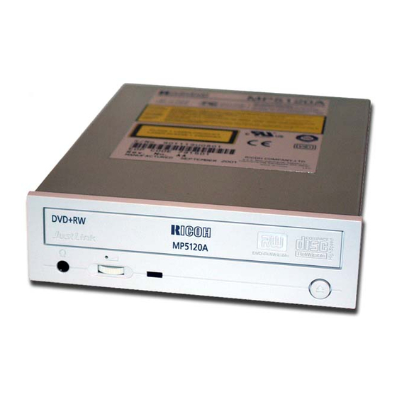
Page 11: Front Panel
Front Panel Rear panel Front Panel Disc tray This is the tray for the disc. Place the disc on the ejected disc tray, then lightly push the tray (or push the eject button) and the disc will be mounted. Caution Don't use force to pull out or push in the disc tray. -
Page 12: Rear Panel
Emergency eject hole This drive has a function that allows the disc to be ejected manually for an emergency case such as failure of the drive or a power outage. Caution This feature is a last measure to be used only in an emergency. Using it excessively will cause malfunction. - Page 13 Emergency Eject This drive has a function that allows the CD to be ejected manually, if this becomes necessary in an emergency such as failure of the drive or a power outage. Follow the following procedures in such a case. Caution This feature is a last measure to be used only in an emergency.
- Page 14 The structure inside the emergency eject hole is as shown below. When you push a thin, stiff wire into the hole, it presses one of the vanes around the gear, thus rotating the gear for ejecting the tray. Repeating this action three times or so ejects the tray out.
- Page 15 Disc ejection Press the eject button Slowly take the disc out of the disc tray Press the eject button or push the disc tray and the tray will be inserted back into the drive.
- Page 16 Caution After ejecting the disc, return the disc tray inside the unit quickly. When the disc tray is in the ejected position, dust and other debris will enter, possibly causing read errors, write errors, or drive failure. Back Next Load the disc Disc ejection Emergency Eject Using the Drive in a Vertical Position...
- Page 17 Load the disc Press the eject button. Place the disc on the disc tray. Be careful not to touch the recording surface of the disc. Cautions DVD-R/RW (DVD minus R/RW) disc media cannot be used. When using a 120-mm CD, place the disc in the larger circular depression with its label side facing upside.
- Page 18 Load the disc by pressing the eject button or by lightly pushing in the disc tray. Next...
- Page 19 Disc ejection Load the disc Emergency Eject Using the Drive in a Vertical Position...
- Page 20 Using the Drive in a Vertical Position The drive can be installed in a vertical position. Locate the four tabs on the disc tray. Turn each of them inwards untill they click into place. When loading a disc, insert it into the inner side of the tabs. Caution Cannot be used with 80mm CDs.
-
Page 21: Installing The Drive
Specific knowledge of hardware and software is necessary to install the drive. We cannot guarantee against direct or indirect damage resulting from improper connections. Ask your supplier for details of the installation procedure. Before Installation Before installing the drive, please note the following points. You will need the following: A Phillips head screw driver of a suitable size to fit the securing screws for the drive unit. - Page 22 1. Jumper Set Up Before installation, set the jumper on the jumper connector on the rear panel. Master (MA) Drive set as Master (factory default) Slave (SL) Drive set as Slave Cable Select (CS) Drive mode set by CSEL on the host IDE interface The drive can be connected as the Master or Slave on an E-IDE (ATAPI) interface.
- Page 23 Only one jumper should be installed on the jumper connector. If more than one jumper is installed, the drive may malfunction or be damaged. Next 2. Removing the Computer Cover 1. Jumper Set Up 3. Mounting the Drive 4. Connecting the Power Connector 5.
- Page 24 2. Removing the Computer Cover Make sure all peripheral devices of the computer and the computer itself are turned off, and then remove the cover. Refer to the manual for the computer for details about removing the cover. Caution There may be sharp edges inside the computer take care to avoid injury. (Example: When newly installing the MP5120A drive into a PC.) Back Next...
-
Page 25: Mounting The Drive
3. Mounting the Drive Remove the 5 inch drive bay panel from the computer. Refer to the manual for the computer for details. Insert the drive unit into the bay. Do not apply excessive pressure to the cables inside the computer. Secure the drive with the screws provided. - Page 26 Back Next 1. Jumper Set Up 2. Removing the Computer Cover 4. Connecting the Power Connector 3. Mounting the Drive 5. PC Connections 6. Sound Card Connection 7. Replacing the Computer Cover 8. Device Drivers...
- Page 27 4. Connecting the Power Connector Connect the power cable from the computer's power supply to the socket on the drive unit, fitting the connector properly into the socket. Back Next 1. Jumper Set Up 2. Removing the Computer Cover 3. Mounting the Drive 4.
- Page 28 5. PC Connections The drive connects to the motherboard of the host computer using an IDE interface cable. Both Primary and Secondary connectors are usually provided on the motherboard, which may be connected as follows: Master Slave Motherboard Primary Secondary less than 6 inches less than 18 inches To Install as a Master Drive...
- Page 30 To Install as a Slave Drive When connecting the drive as a slave drive, change the position of the slave setting jumper pin on the rear of the system unit. Master drive (Booting hard disk) Slave drive (MP5120A) Secondary connector Primary connector Master drive (Other IDE drive)
- Page 31 Back Next 1. Jumper Set Up 2. Removing the Computer Cover 3. Mounting the Drive 4. Connecting the Power Connector 6. Sound Card Connection 5. PC Connections 7. Replacing the Computer Cover 8. Device Drivers...
-
Page 32: Sound Card Connection
6. Sound Card Connection If the computer has a sound card, the drive can be connected to the sound card with an audio cable. Make sure the connections are oriented so that L corresponds to L and R to R. Refer to the manual for the sound card for detailed information regarding connection. - Page 33 1. Jumper Set Up 2. Removing the Computer Cover 3. Mounting the Drive 4. Connecting the Power Connector 5. PC Connections 6. Sound Card Connection 7. Replacing the Computer Cover 8. Device Drivers...
- Page 34 7. Replacing the Computer Cover When the installation of the drive unit is complete, replace the computer cover. Back Next 1. Jumper Set Up 2. Removing the Computer Cover 3. Mounting the Drive 4. Connecting the Power Connector 5. PC Connections 6.
-
Page 35: Device Drivers
8. Device Drivers When using Windows 98/95, Window NT Workstation Ver. 4.0, Windows 2000 (Professional) the installation of any special device drivers are not required. In order to ensure normal drive operation or if the drive is not recognized by your computer, please check the following: In order to ensure normal drive operation If the drive is not recognized by your computer... - Page 36 After checking the above-mentioned points, contact the manufacturer of your PC or PC mother-board, if applicable, to obtain an appropriate IDE controller driver. Back 1. Jumper Set Up 2. Removing the Computer Cover 3. Mounting the Drive 4. Connecting the Power Connector 5.
- Page 37 Caution When using CD-ROM discs, DVD-ROM discs, CD-R discs or CD-RW discs, do not attach any stickers or labels to the discs. Using discs with labels attached not only causes read and write errors, but data on the disc may be lost due to damage to the disc itself. Load the disc Disc ejection Emergency Eject...
- Page 38 Drive : MP5120A Type Internal type Interface Enhanced-IDE (ATAPI) Data buffer memory Data transfer speed 33.3MB/sec. (Max.) (Ultra DMA mode2) CD-RW/High Speed Read Speed CD-RW Write/Read speed 600KB/sec. (Ave.) 1200KB/sec. 20X: 3000KB/sec. 32X: 4.8MB/sec. Write Speed CD-R: 600KB/sec. 1200KB/sec. 12X: 2.1MB/sec.
- Page 39 CD-Text DVD-ROM DVD-RW Loading system Tray type (automatic loading/eject) Power DC5V, DC12V Power consumption Weight Less than 1.2 Kg. Dimensions 146 X 196.5 X 41.3mm Reliability Error Rate: bits or less MTBF: 100,000hours or greater MTTR: Within 30 minutes Environmental Conditions When operating When not operating Temperature...
- Page 40 * All references to the product in this document are to specifications in effect when the product was released. Copyright RICOH Co.Ltd. All rights reserved.
Need help?
Do you have a question about the MP5120A and is the answer not in the manual?
Questions and answers