JVC KD-AVX33 Installation & Connection Manual
Hide thumbs
Also See for KD-AVX33:
- Instruction manual (213 pages) ,
- Instructions manual (74 pages) ,
- Installation manual (6 pages)
Advertisement
Quick Links
KD-AVX33
Installation/Connection Manual
LVT1708-004A
[A]
This unit is designed to operate on 12 V DC, NEGATIVE ground electrical systems. If your vehicle does
not have this system, a voltage inverter is required, which can be purchased at JVC car audio dealers.
WARNINGS
• DO NOT install any unit and wire any cable in locations where;
– it may obstruct the steering wheel and gearshift lever operations, as this may result in a traffic accident.
– it may obstruct the operation of safety devices such as air bags, as this may result in a fatal accident.
– it may obstruct visibility.
• DO NOT operate any unit while manipulating the steering wheel, as this may result in a traffic accident.
• The driver must not watch the monitor while driving. If the driver watches the monitor while driving, it
may lead to carelessness and cause an accident.
• The driver must not put on the headphones while driving. It is dangerous to shut off the outside sounds
while driving.
• If you need to operate the unit while driving, be sure to look around carefully.
• If the parking brake is not engaged, "Parking Brake" appears on the monitor, and no playback picture
will be shown.
– This warning appears only when the parking brake lead is connected to the parking brake system built
in the car.
Notes on electrical connections:
• Replace the fuse with one of the specified rating. If the fuse blows frequently, consult your JVC car audio
dealer.
• It is recommended to connect to the speakers with maximum power of more than 50 W (both at the rear
and at the front, with an impedance of 4 Ω to 8 Ω).
If the maximum power is less than 50 W, change "Amplifier Gain" setting to prevent the speakers from
being damaged (see page 51 of the INSTRUCTIONS).
• To prevent short-circuit, cover the terminals of the UNUSED leads with insulating tape.
• The heat sink becomes very hot after use. Be careful not to touch it when removing this unit.
Heat sink
Required space for installation
Control panel
Caution when installing
Fit the unit into the mounting sleeve by using four corners of the trim plate.
• DO NOT press the panel (shaded in the illustration).
INSTALLATION (IN-DASH MOUNTING)
The following illustration shows a typical installation. If you have any questions or require information regarding installation kits, consult your JVC car audio dealer or a company supplying kits.
• If you are not sure how to install this unit correctly, have it installed by a qualified technician.
• Make sure not to block the fan on the rear panel to maintain proper ventilation when installed.
• You cannot install the unit on the car which has any obstacles in the space shown in "Required space for installation" above.
Dashboard
Trim plate is detached on this
illustration for explanation.
5 mm
5 mm
*
1
When you stand the unit,
be careful not to damage
the fuse on the rear.
Parts list for installation and connection
The following parts are provided for this unit. After checking them, please set them correctly.
A
/
B
C
Hard case/Control panel
Sleeve
F
G
Audio/video cord
Crimp connectors
K
L
Microphone clip
Microphone
N
o
Washer (ø5)
Lock nut (M5)
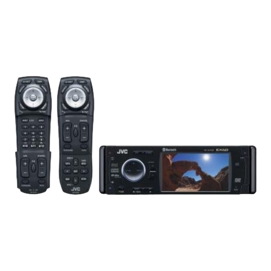
Installing the remote controller
Remote controller
Do the required electrical connections.
Do not block the fan.
1
0207MNMMDWJEIN
©2007 Victor Company of Japan, Limited
D
E
Trim plate
Power cord
H
I
Remote controller / Holder
Batteries
J
Double-sided
adhesive tape
M
Reverse gear signal extension cord
P
Q
R
Handles
Rubber cushion
Mounting bolt—
M5 x 20 mm
Holder
Double-sided
adhesive tape
Bend the appropriate
tabs to hold the sleeve
firmly in place.
Fit the protrusions
outside the unit.
EN
Advertisement

Related Manuals for JVC KD-AVX33


Summary of Contents for JVC KD-AVX33
- Page 1 INSTALLATION (IN-DASH MOUNTING) The following illustration shows a typical installation. If you have any questions or require information regarding installation kits, consult your JVC car audio dealer or a company supplying kits. • If you are not sure how to install this unit correctly, have it installed by a qualified technician.
- Page 2 When using the optional stay When installing the unit without using the sleeve Stay (option) In a car having the “Required space for installation” (see page 1), first remove the car radio and install the unit in its place. Fire wall Flat type screws—M5 x 8 mm Not included for this unit.
-
Page 3: Electrical Connections
ELECTRICAL CONNECTIONS To prevent short circuits, we recommend that you disconnect the battery’s negative terminal and make all electrical connections before installing the unit. PRECAUTIONS on power supply and speaker connections: • Be sure to ground this unit to the car’s chassis again after installation. •... -
Page 4: Troubleshooting
Audio cord (not supplied) Before connecting the external components, make sure that the unit is turned off. • To use JVC CD changer, Apple iPod or JVC D. player, set “External Input” to “Changer/iPod/D. External Player” (see page 50 of the INSTRUCTIONS).
Need help?
Do you have a question about the KD-AVX33 and is the answer not in the manual?
Questions and answers