Table of Contents
Advertisement
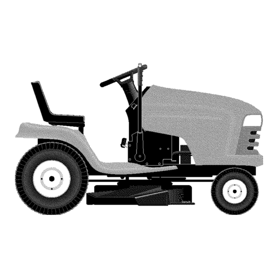
Owner's Manual
J CRIIFTSMIIN°J
LAWN TRACTOR
25.0 HP, 48" Mower
Electric Start
Automatic Transmission
Model No.
917.273240
[_
This product has a low emission engine which operates differently
from previously
built engines.
Before you start the engine, read
and understand
this Owner's Manual.
IMPORTANT:
Read and follow all
Safety Rules and Instructions
before operating this equip-
ment.
For answers
to your questions
about
this product, Call:
1-800-659-5917
Sears Craftsman
Help Line
5 am - 5 pm, Mon - Sat
Sears, Roebuck and Co., Hoffman Estates, IL 60179
U.S.A.
Visit our Craftsman website: www.sears.com/craftsman
Advertisement
Table of Contents

Related Manuals for Craftsman 917.273240


Summary of Contents for Craftsman 917.273240
- Page 1 Read and follow all 1-800-659-5917 Safety Rules and Instructions Sears Craftsman Help Line before operating this equip- 5 am - 5 pm, Mon - Sat ment. Sears, Roebuck and Co., Hoffman Estates, IL 60179 U.S.A. Visit our Craftsman website: www.sears.com/craftsman...
- Page 2 IN HOME warranty service will still be available after the first 30 days of pur- chase, but a trip charge will apply. This charge will be waived if the Craftsman product is dropped off at an authorized Sears location. For the nearest authorized Sears location, please call 1-800-4-MY-HOME®.
- Page 3 IMPORTANT: This cutting machine is capable of amputating hands and feet and throw- ing objects. Failure to observe the following safety instructions could result in serious injury or death. • Be aware of the mower discharge direc- _WARNING: In order to prevent ac- tion and do not point it at anyone.
- Page 4 • Never carry children. They may fall off and be seriously injured or interfere with • Mow up and down slopes, not across. safe machine operation. • Remove obstacles such as rocks, tree • Never allow children to operate the limbs, etc.
- Page 5 • Remove obstacles such as rocks, tree • Be sure the area is clear of other people limbs, etc. before mowing. Stop machine if anyone enters the area. • Watch for holes, ruts, or bumps. Uneven terrain could overturn the machine. Tall •...
- Page 6 Here's what's included in the Agreement: _WARNING: This tractor is equipped • Expert service by our 12,000 profe- with an internal combustion engine and sional repair specialists. should not be used on or near any unim- • Unlimited service and no charge for proved forest-covered, brush-covered parts and labor on all covered repairs.
- Page 7 Your new tractor has been assembled at the factory. Review the video cassette before you begin. When right or left hand is mentioned in this manual, it means, from your point of view, when you are in the operating posi- tion (seated behind the steering wheel).
- Page 8 JCHECKLIST 6. Start the engine. After engine has started, move throttle control to idle Before you operate your new tractor, we position. wish to assure that you receive the best 7. Release parking brake. performance and satisfaction from this 8. Slowly depress forward drive pedal and Quality Product.
- Page 9 These symbols may appear on your tractor or in literature supplied with the product. Learn and understand their meaning. I'.,I REVERSE NEUTRAL HIGH CHOKE FAST SLOW IGNITION ENGINE OFF LIGHTS ON ENGINE ENGINE START PARKING BRAKE PARKING BRAKE PARKING BRAKE LOCKED UNLOCKED OVER TEMP...
- Page 10 KNOW YOUR TRACTOR READ THIS OWNER'S MANUAL AND SAFETY RULES BEFORE OPERATING YOUR TRACTOR Compare the illustrations with your tractor to familiarize yourself with the locations of various controls and adjustments. Save this manual for future reference. Hourmeter Switch Position Ignition Attachment Clutch Switch Switch...
- Page 11 The operation of any tractor can result in foreign objects thrown into the eyes, which can result in severe eye damage. Always wear safety glasses or eye shields while operating your tractor or performing any adjustments or repairs. We recommend standard safety glasses or a wide vision safety mask worn over spectacles.
- Page 12 TO ADJUST MOWER CUTTING HEIGHT remain fully and centrally positioned in the seat to prevent the engine from hesitating The position of the attachment lift lever or cutting off when operating your equip- determines the cutting height. • Grasp lift lever. ment on rough, rolling terrain or hills.
- Page 13 Transmission Engaged CAUTION: Alcohol blended fuels (called gasohol or using ethanol or methanol) can attract moisture which leads to separa- tion and formation of acids during storage. Acidic gas can damage the fuel system of an engine while in storage. To avoid engine problems, the fuel system should be emptied before storage of 30 days or longer.
- Page 14 7. When engine starts, slowly push choke NOTE: During this step there will be no movement of drive wheels. The air is being control in until the engine begins to run smoothly. Continue to push the choke removed from hydraulic drive system. control in small steps allowing the engine 5.
- Page 15 FILL IN DATES _0/_ ,XO' ,_C_ ,_._ _-£_ _9._ _,4._ e.4,_ _,4,_ e.4_ _,._ _e-_ DATES AS YOU COMPLETE R EGU LAR SERVICE /___ICE Check Operator Presence Interlock Systems Check for Loose Fasteners Lubrication Chart Check Baitery Level Sharpen/Replace Mower Blades Clean Battery...
- Page 16 TRACTOR IMPORTANT: To ensure proper assembly, center hole in blade must align with star Always observe safety rules when per- on mandrel assembly. forming any maintenance. Install and tighten blade bolt securely BRAKE OPERATION (45-55 Ft. Lbs. torque). If tractor requires more than six (6) feet IMPORTANT: Special blade bolt is heat...
- Page 17 NOTE: The original equipment battery on your tractor is maintenance free. Do not attempt to open or remove caps or covers. Adding or checking level of electrolyte is not necessary. TO CLEAN BATTERY AND TERMINALS Corrosion and dirt on the battery and terminals can cause the battery to "leak"...
- Page 18 ENGINEOIL FILTER CLEAN AIR INTAKE/COOLING AREAS Replacethe engine oil filter every season To insure proper cooling, make sure the or everyother oil change if the tractoris grass screen, cooling fins, and other external surfaces of the engine are kept used morethan 100 hours in one year. clean at all times.
- Page 19 WARNING:TO AVOID SERIOUS INJURY, BEFORE PERFORMING ANY SER- VICE OR ADJUSTMENTS: 1. Depress brake pedal fully and set parking brake. 2. Place attachment clutch in "DISENGAGED" position. 3. Turn ignition key "STOP" and remove key. 4. Make sure the blades and all moving parts have completely stopped. 5.
- Page 20 Bubble Between 9. Position front plate assembly between Bubble Level front mower brackets. Raise deck and Lines plate assembly to align holes and insert flanged pins. Secure pins with double loop retainer springs between Decal the plate assembly and mower brack- ets.
- Page 21 TO REPLACE MOWER DRIVE BELT To obtain the best cutting results, the mower blades should be adjusted so the MOWER DRIVE BELT REMOVAL front tip is approximately 1/8" to 1/2" lower 1. Park tractor on a level surface. Engage than the rear tip when the mower is in its parking brake.
- Page 22 B.H. Mandrel Cover Belt Tension Rod (Disengaged Electric Position) _,,,_; Pulley Idler Pulleys R.H. Mandrel Spring Arm R.H. Suspension Primary Idler Arm TO REPLACE MOWER BLADE 10. Check secondary idler arm and idler pulley to see that they rotate freely. (SECONDARY) DRIVE BELT 11.
- Page 23 Secondary Idler Arm Idler Pulley L.H. ring Mandrel Secondary Mandrel Mower Blade (Secondary) Drive Belt R.H. Mandrel TO CHECK AND ADJUST BRAKE 5. Road test tractor for proper stopping distance as stated above. Readjust Your tractor is equipped with an adjustable if necessary.
- Page 24 TO REMOVE WHEEL FOR REPAIRS 5. Removebelt downwardfrom engine pulleyand around electricclutch. 1. Block up axle securely. 6. Pull belt slack toward rearof tractor. 2. Remove axle cover, retaining ring and Carefullyremovebelt upwardsfrom washers to allow wheel removal (rear transmissioninput pulleyand over wheels have a square key - Do not coolingfan blades.
- Page 25 5. Reconnect harness to lamp assembly. 6. Close hood. INTERLOCKS AND RELAYS Loose or damaged wiring may cause your tractor to run poorly, stop running, or prevent it from starting. • Check wiring. See electrical wiring diagram in the Repair Parts section. TO REPLACE FUSE Weak or Dead Fully Charged...
- Page 26 TO ADJUST CHOKE CONTROL In general, turning the adjusting needles in (clockwise) decreases the supply of The choke control has been preset at the fuel to the engine giving a leaner fuel/air factory and adjustment should not be nec- mixture. Turning the adjusting needles out essary, check adjustment...
- Page 27 Immediatelyprepareyour tractorfor stor- blended fuels (called gasohol or using age at the end of the season or if the trac- ethanol or methanol) can attract moisture which leads to separation and formation of _will not be used for 30 days or more. CAUTION: Never store the tractor acids during storage.
- Page 28 TROUBLESHOOTING CHART: See appropriate section in manual unless directed to Sears service center PROBLEM CAUSE CORRECTION Will not start 1. Out of fuel. 1. Fill fuel tank. 2. See "TO START ENGINE" in 2. Engine not "CHOKED" properly. Operation section. 3.
- Page 29 TROUBLESHOOTING CHART: See appropriate section in manual unless directed to Sears service center CAUSE CORRECTION PROBLEM 4. Clean/replace air filter. LOSS of power 4.Dirty air filter. 5. Check oil level/change oil. (continued) Low oil level/dirty oil. 6. Clean and regap or change Faulty spark plug.
- Page 30 TROUBLESHOOTING CHART: See appropriate section in manual unless directed to Sears service center PROBLEM CAUSE CORRECTION 1. Place throttle control in iPoor grass Engine speed too slow. idischarge "FAST" position. Travel speed too fast. 2. Shift to slower speed. Wet grass. 3.
- Page 31 TRACTOR - - MODEL NUMBER 917.273240 SCHEMATIC lilili BATTERY FUSE STARTER AMMETER (OPTIONAL) W,ITE SOLENOID CLUTCH/DRAKE (PEDAL SEAT SWITCH (NOT OCCUPIED) • i 85 86 i PTOL(DtSE I 87 "_) 87A FUEL I OPERATOR PRESENCE RELAY #1 IGNITION II__LI_I BLUE LINE PLUG SPARK...
- Page 32 TRACTOR - - MODEL NUMBER 917.273240 ELECTRICAL...
- Page 33 TRACTOR - - MODEL NUMBER 917.273240 ELECTRICAL PART DESCRIPTION 144927 Battery 74760412 Bolt, Hex 1/4-20 x 3/4 7603J Tray, Battery 145211 Bolt, Battery, Front 1/4-20 x 7-1/2 150109 Holddewn, Battery, Front 145769 Nut, Push, Nylon, Battery, Front 1/4 176138 Switch, Interlock 175449 Harness, Light 178909...
- Page 34 TRACTOR - - MODEL NUMBER 917.273240 CHASSIS AND ENCLOSURES 166_ _166 /142 chassis-LTX-s...
- Page 35 TRACTOR - - MODEL NUMBER 917.273240 CHASSIS AND ENCLOSURES PART DESCRIPTION 174619 Chassis 176554 Drawbar 17060612 Screw, 3/8-16x3/4 172542X418 Dash 72140608 Bolt RDHD SQNK 3/8-16 x 1 174996 Panel, Dash, LH 179174X010 Panel, Dash, RH 17490608 Screw Thdrol 3/8-16 x 1/2 172540X615 Hoed Assembly 180679...
- Page 36 TRACTOR - - MODEL NUMBER 917.273240 GROUND DRIVE "239 2._1 29'_ 26 h drive-hydro.stlt...
- Page 37 TRACTOR - - MODEL NUMBER 917.273240 GROUND DRIVE PART PART DESCRIPTION DESCRIPTION 121748X Washer 25/32 x 1-5/8 x 16 Ga. - - - Transaxle, HydroGear, Model Number 336-0510 (See Break 174901X418 Console, Shift Nut Self-Thd Wsh-hd 1/4 Zinc down) 124346X 17060512 Screw 5/16-18 180825...
- Page 38 TRACTOR - - MODEL NUMBER 917.273240 STEERING ASSEMBLY .._ i_1 steering+.pMt45...
- Page 39 TRACTOR - - MODEL NUMBER 917.273240 STEERINGASSEMBLY PART DESCRIPTION 175139X418 Wheel Steering 184706 Axle Asm 169840 Spindle Asm LH 169839 Spindle Asm RH 6266H Bearing Race Thrust Harden 121748X Washer 25/32 x 1-5/8 x 16 Ga 12O00O29 Ring Klip #t5304-75 175121 Link Drag STD551137...
- Page 40 TRACTOR - - MODEL NUMBER 917.273240 ENGINE OPTIONAL EQUIPMENT Spark Arrester engine_ko,twinJ...
- Page 41 TRACTOR - - MODEL NUMBER 917.273240 ENGINE PART DESCRIPTION 175439X505 Control, Throttle 171875 Screw Hwhd Hi-Lo #13-16 x 314 - - - Engine, Kohler, Model Number CV730-0018 (See Breakdown) 149723 Muffler, Asm. Twin Lo-Tone 146700 Pipe Exhaust Intek 20 RH 146699 Pipe Exhaust Intek 20 LH 171877...
- Page 42 TRACTOR - - MODEL NUMBER 917.273240 SEAT ASSEMBLY seatjt.knob2 KEY PART KEY PART NO. NO. DESCRIPTION DESCRIPTION 175134 Seat 121248X Bushing Snap BIk Ny150 Id 140551 Bracket Pivot Seat 8 720 72050412 Bolt Rdhd Sqnk 1/4-20 x 14/2 STD523710 Bolt Fin Hex 3/8-16 Unc x 1 121249X Spacer Split 28x .88 Zinc 19131610...
- Page 43 Decal, Steering Wheel 186329 Decal, Hood RH 177955 Decal, Fender, Cruise 186330 Decal, Hood LH 177914 Decal, Engine, Kohler 180978 Decal, Seat Craftsman 149516 Decal, Battery 146046 Decal, Hood, Side Panel Decal, V-Belt, Drive Schematic 186331 185980 Decal, Engine 177889...
- Page 44 TRACTOR - - MODEL NUMBER 917.273240 LIFT ASSEMBLY lift-rh.l piecej...
- Page 45 TRACTOR - - MODEL NUMBER 917.273240 LIFT ASSEMBLY PART DESCRIPTION 179504 Plunger Assembly 159476 Shaft Assembly, Lift 178981 Pin, Groove 12000002 E-Ring 19211621 Washer 21/32xl x21 Gauge 120183X Bearing, Nylon 175830 Grip, Handle, Fluted 175370 Link, Lift, L.H. 175371 Link, Lift, R.H. 4939M Retainer Spring 175562...
- Page 46 TRACTOR - - MODEL NUMBER 917.273240 MOWER DECK 33"_ mower deck.48prem stir I...
- Page 47 TRACTOR - - MODEL NUMBER 917.273240 MOWER DECK KEY PART PART NO. NO. DESCRIPTION DESCRIPTION 180358 Deck Weldment Mower 48 72110612 Bolt, Carr. 3/8-16 x 1-1/2 Gr. 5 138017 175820 Bracket Asm., Sway Bar Pulley Idler Flat 4939M 74780616 Bolt Fin Hex 3/8-16 Uric x 1 Gr. 5 Retainer Spring 178024 72140608...
- Page 48 "-19 ,.L, M .!24 €) 6-Sealant (Joint d' etancheite) 57-20W50 Oil - 78,80Z (OZ de 78.820 d' Huile) 127 - Seal and O-ring Kit (Phoque 0 Sonne Jeu)
- Page 49 TRACTOR - - MODEL NUMBER 917.273240 HYDRO GEAR TRANSAXLE -- MODEL NUMBER 336-0510 PART PART DESCRIPTION DESCRIPTION Arm, Brake 170351 Main Housing, Assembly 178782 Slotted Hex Nut 5/16-24 170352 Side Housing, Assembly 170415 Cotter Pin 3/32 X 3/4 170353 Center Section, Assembly 170416 Compression Spring Brake Anti- 170354...
- Page 50 TRACTOR - - MODEL NUMBER 917.273240 KOHLER ENGINE-MODEL NUMBER CV730TYPE NUMBER 0018 CYLINDER HEAD, VALVE AND RREATHERT_ _34i _ 16 CRANKCASEJ / o-'== ..15"...
- Page 51 TRACTOR - - MODEL NUMBER 917.273240 KOHLER ENGINE-MODEL NUMBER CV730 TYPE NUMBER 0018 CRANKCASE HEAD/VALVE/BREATHER PART PART DESCRIPTION DESCRIPTION Seal, front oi_ 24-033-01-S Kit, breather cover w/gasket 24-032-01-S Crankcase (Includes 2-4) (USE: Miniblock 24 782 24) 24-041-23-S Gasket, breather Fitting 24-096-87-S Cover, breather 24-294-13-S...
- Page 52 TRACTOR - - MODEL NUMBER 917.273240 KOHLER ENGINE-MODEL NUMBER CV730TYPE NUMBER 0018 IGNITIONJELECTRICALJ BLOWER HOUSING AND BAFFLESJ...
- Page 53 TRACTOR - - MODEL NUMBER 917.273240 KOHLER ENGINE-MODEL NUMBER CV730TYPE NUMBER 0018 BLOWER HOUSING & BAFFLES IGNITION/ELECTRICAL PART PART DESCRIPTION DESCRIPTION 24-027-114-S Housing, blower 54-755-15-S Kit, grass screen (Includes (Incl. 2-4) 2-4,and 24 113 18-S) 24-100-01-S Nut plastic (2) M-403025-S Screw, hex.
- Page 54 TRACTOR - - MODEL NUMBER 917.273240 KOHLER ENGINE-MODEL NUMBER CV730TYPE NUMBER 0018 STARTING SYSTEMJ ENGINECONTROLSJ _ 27 OiL PAN / LUBRICATION j___'J 11f'_...
- Page 55 TRACTOR - - MODEL NUMBER 917.273240 KOHLER ENGINE-MODEL NUMBER CV730TYPE NUMBER 0018 STARTING SYSTEM OIL PAN/LUBRICATION PART PART DESCRIPTION DESCRIPTION 24-199-07-S M-839080-S Screw, hex.flange Pan assembly, oil M8x1.25x80 (2) olnCludes 2-11 ) 25-098-09-S Starter, solenoid shift assem 24-393-37-S il pump assembly (Includes bly (Includes 3-7) 3,4) 25 086 113-S Screw, external torx.
- Page 56 TRACTOR - - MODEL NUMBER 917.273240 KOHLER ENGINE-MODEL NUMBER CV730TYPE NUMBER 0018 EXHAUST CRANKSHAFT FUEL SYSTEM...
- Page 57 TRACTOR - - MODEL NUMBER 917.273240 KOHLER ENGINE-MODEL NUMBER CV730TYPE NUMBER 0018 FUEL SYSTEM CRANKSHAFT PART PART DESCRIPTION DESCRIPTION 24-853-90-S Kit, carburetor w/gaskets 24-014-42-S Crankshaft (includes2) (includes 2-4) 52-139-09-S Plug, cup 24-041-52-S Gasket, carburetor 24-053-90 Carburetor assembly EXHAUST (For information only not available separately) PART (Service with kits 24-757-18-...
- Page 59 SUGGESTED GUIDE FOR SIGHTING SLOPES FOR SAFE OPERATION down the face of slopes, never across the face. Do not mow ARNING: To avoid serious injury, operate your tractor up and slopes greater than 15 degrees. Make turns gradually to prevent tipping or loss of control.
- Page 60 Your Home For repair - in your home - of all major brand appliances, lawn and garden equipment, or heating and cooling systems, no matter who made it, no matter who sold it! For the replacement parts, accessories owner's manuals that you need to do-it-yourself. For Sears professional installation of home appliances...
Need help?
Do you have a question about the 917.273240 and is the answer not in the manual?
Questions and answers