Table of Contents
Advertisement
SEARS
OWNER'S
MANUAL
MODEL NO.
225.581508
15" TRANSOM
225.581498
20" TRANSOM
CAUTION:
Read and Follow
all Safety Rules
and Instructions
Before Operating
This Equipment
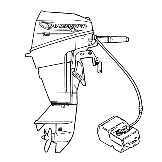
GAMEFISHER
15 HORSEPOWER
OUTBOARD MOTOR
WITH 6 GALLON REMOTE TANK
• Installation
• Operation
• Customer
Responsibilities
• Service Adjustments
• Repair Parts
Sears Roebuck and Co., Hoffman Estates, IL 60179 U.S.A.
Advertisement
Table of Contents

Related Manuals for Sears GAMEFISHER 225.581508


Summary of Contents for Sears GAMEFISHER 225.581508
- Page 1 SEARS OWNER'S MANUAL MODEL NO. 225.581508 15" TRANSOM 225.581498 20" TRANSOM GAMEFISHER CAUTION: Read and Follow 15 HORSEPOWER all Safety Rules OUTBOARD MOTOR and Instructions WITH 6 GALLON REMOTE TANK Before Operating This Equipment • Installation • Operation • Customer Responsibilities •...
- Page 2 SAFETY RULES BOATER'S RESPONSIBILITIES The operator (driver) is responsible for the correct USING AN OUTBOARD THAT EXCEEDS THE MAXI- safe operation of the boat and safety of its occupants HORSEPOWER LIMIT OF A BOAT CAN: and general public. It is strongly recommended that 1.
-
Page 3: Specifications
CONGRATULATIONS... PRODUCT SPECIFICATIONS You are to be congratulated on your selection of this Engine 15 HP Outboard Motor which will give you years of satisfactory Horsepower Rating @ 6000 RPM service. Your Gamefisher is the end product of years of Recommended research, engineering and development. - Page 4 TABLE OF CONTENTS CUSTOMER RESPONSIBILITIES ..... 17-24 SAFETY RULES ......... MOTOR SPECIFICATIONS ...... SERVICE AND ADJUSTMENTS ....WARRANTY ........STORAGE ........26-27 MOTOR ACCESSORIES ......TROUBLESHOOTING POINTS ....INSTALLATION ......... REPAIR PARTS ........ MOTOR NOMENCLATURE ...... PARTS ORDERING ....REAR COVER OPERATION .........
-
Page 5: Accessories
OUTBOARD MOTOR ACCESSORIES These accessories were available when the outboard motor was purchased. They are also available at most Sears retail outlets, catalog and service centers. Most Sears stores can order repair parts for you, when you provide the model number of your outboard motor. - Page 6 GENERAL INFORMATION LANYARD STOP SWITCH DISADVANTAGES: INADVERTENT ACTIVATION THE SWITCH IS ALSO A POSSIBILITY. THIS COULD The purpose of the lanyard stop switch is to turn off CAUSE ANY, OR ALL, OF THE FOLLOWING POTEN- the engine ignition whenever the operator (when TIALLY HAZARDOUS...
-
Page 7: Removing Motor
INSTALLATION BOATTRANSOM TRANSOM TYPE • Make sure the transom of your boat is designed for mounting an outboard motor. (Figure 1) The keel should be tapered from a point about 30" (76.2cm) ahead of the transom so that it is no more than 1/2" (1.27cm) thick at the transom. - Page 8 OPERATION KNOW YOUR OUTBOARD MOTOR Read this owner's manual and safety rules before operating your outboard motor. Compare the illustrations (Figures and 5) with your outboard motor to familiarize yourself with the location of various controls and adjustments. Save this manual for future reference.
-
Page 9: Steering Friction
OPERATION TO USE YOUR OUTBOARD MOTOR MOTOR TILT • To tilt the motor up out of the water push tilt release lever down to "Release" position. (Figure 6) • Grasp handle on back of motor cover and pull forward until end of travel of tilt stop. -
Page 10: Shallow Water Drive Bar
OPERATION SHALLOW WATER DRIVE TILLER HANDLE POSITIONS The shallow water drive bar allows the motor to operate The motor is equipped with a throttle arm that drops at low speeds in shallow water. down for convenient handling during transportation storage. To drop the handle, lift the arm up slightly,... - Page 11 OPERATION MOTOR TILT ANGLE IMPORTANT: ADJUST MOTOR TILT ANGLE, IF NECESSARY, BY CHANGING THE POSITION OF THE LOCK BAR SO THAT THE PROPELLER SHAFT IS PARALLEL TO THE SURFACE OF THE WATER WHEN THE BOAT IS PLANING. SEE FIGURE 15 TO DETERMINE CORRECT MOTOR ANGLE.
- Page 12 OPERATION BEFORE STARTING ENGINE FOR A PROPER FUEL MIX OIL SELECTION Recommended lubricant and gasoline must be properly mixed or serious damage will result to the engine. • Use NMMA certified TC-W3 or TC-W II outboard oil. • Maintain a clean fuel tank. GASOLINE SELECTION •...
- Page 13 • OPERATION BREAK-IN PROCEDURE -- USE 25:1 MIX ,A CAUTION SEVERE DAMAGE TO THE ENGINE CAN RESULT BY NOT COMPLYING WITH FOLLOWING BREAK-IN PROCEDURE. • Mix correct amount of outboard motor oil with each gallon of gasoline (see gasoline -- oil mixture require- ments and fuel ratio conversion table).
-
Page 14: Start Engine
OPERATION TO STOP • Shift lever (A) must be in neutral position, when starting. The motor has a lock out device that pre- Retard throttle control to "slow" position, shift engine into "neutral." Depress "stop" button (E) and hold until motor vents the motor from starting when in gear. - Page 15 OPERATION OPERATING CHECKS AND CHECK COOLING SYSTEM Cooling water ispicked up on the side ofthe gear housing just ahead of the propeller, goes through the powerhead, and then goes out with the exhaust gases. IMPORTANT: NEVER RUN MOTOR OUT OF THE WA- TER, AND NEVER RUN MOTOR UNLESS WATER PUMP IS WORKING NORMALLY OR OVERHEATING AND MO- TOR DAMAGE MAY RESULT.
-
Page 16: Salt Water Operation
OPERATION SHAKEDOWN CHECKLIST IMPORTANT: IF THE MOTOR IS TILTED OUT OF THE WATER, WATER REMAINING IN THE COOLING SYSTEM Operator has read and understood the entire opera- AND GEAR HOUSING MAY FREEZE AND CAUSE PARTS tor's manual. TO BREAK. Operator has carried out pre-operation checklist. •... - Page 17 CUSTOMER RESPONSIBILITIES MAINTENANCE SCHEDULE/ ._ /.o,. ._j/_o_.# F.,,._ates as .o,, I/' _;_ lt._f l _"._t ..:#I/'&"'! .&_'! SERVICE DATES complete regular service ._o- Check for loose fasteners • Check fuel pump filter • Check fuel tank filter • Check spark plug •...
- Page 18 CUSTOMER RESPONSIBILITIES TO REMOVE MOTOR COVER PUSH DOWN REMOVE OR INSTALL COVER WHILE MOTOR IS RUNNING. THE COVER PROTECTS YOU FROM MOVING PARTS, WHICH COULD CATCH HANDS, HAIR OR CLOTHING AND CAUSE SERIOUS INJURY. • Push down hard on cover and turn cover release lever REAR on rear of motor.
-
Page 19: Remove Motor Cover
CUSTOMER RESPONSIBILITIES FUEL PUMP FILTER PUMP COVER • Remove motor cover. • Remove fuel line from pump. (Figure 22) • Remove filter/fitting from pump cover. NOTE: FILTER IS PART OF THE FUEL FITTING. • Clean or replace filter. • Reinstall filter/fitting and connect fuel line and secure with clamp. -
Page 20: Spark Plug
CUSTOMER RESPONSIBILITIES SPARK PLUG • Remove motor cover. • Disconnect spark plug lead by twisting slightly and pulling (Figure 24). FIGURE 24 • Remove, clean and inspect spark plug. (Figure 25). • Replace plug if tip of insulator is rough, cracked, bro- ken or blistered, or if the electrodes are eroded. - Page 21 CUSTOMER RESPONSIBILITIES COOLING SYSTEM • If motor overheats, have your Sears Service Center check the water pump for damage. PROPELLER Your motor comes with a propeller designed for good all-around performance on most boats. Check that motor is not over-rewing (R.RM.
- Page 22 CUSTOMER RESPONSIBILITIES LUBRICATION NOTE: Bold letters indicate type of lubrication as specified below, CARBLINKAGE SHIFT LINKAGE CLAMP SCREWS SHIFT LINKAGE WARM UP BUTTON LINKAGE SWIVELBRACKET & GREASEFITTING GEAR HOUSING PROPELLER SHAFT FIGURE LUBRICATION CODE A. Sears Outboard Gear Lube. (If not available, use non-corrosive, EP 90 outboard gear lube.)
- Page 23 CUSTOMER RESPONSIBILITIES DRAINING GEAR HOUSING LUBRICANT • With motor upright, remove the vent screw and the fill and drain screw. Allow lubricant to drain completely (Figure 32). IMPORTANT: WHEN ADDING OR CHANGING LUB- RICANT, INSPECT FOR WATER CONTAMINATION. TO INSPECT, LOOSEN (DO NOT REMOVE) GEAR HOUSING DRAIN...
-
Page 24: Submerged Motor Fresh Water
CUSTOMER RESPONSIBILITIES SPECIAL SITUATIONS If motor starts, run for at least an hour until parts thoroughly warmed up and water has evaporated from SUBMERGED MOTOR FRESH WATER moving parts inside. • If motor is recovered within a few hours, is not SUBMERGED MOTOR SALT WATER... -
Page 25: Initial Setting
SERVICE AND ADJUSTMENTS CARBURETOR NOTE: Adjust the carburetor for better starting and low speed operation when there are changes in temperature, humidity or barometric pressure. The high speed system, which meters fuel from high idle to wide open throttle, is factory equipped with a jet that is not adjustable. -
Page 26: Storage
STORAGE PREPARATION FOR STORAGE © • We recommend that your Sears Service Center pre- pare your motor for storage during the off season for long periods of time. • The Service Center has the latest tools, materials and information and can also carry out maintenance required. - Page 27 STORAGE • Remove spark plug and put an ounce or two of out- board oil into spark plug hole (Figure 42). • Reinstall spark plug. • Pull starter rope several times to lubricate piston, rings and cylinder walls and to remove water from cooling system.
-
Page 28: Points
TROUBLESHOOTING POINTS FL'el Line Air Locked Fuel Une Not Connected Fuel Tank Empty Recirculating Fuel System Dirty or Clogged Fuel Line Kinked or Pinched Fuel Filters Dirty or Clogged Vent Screw Gasket Obstructing Air Flow Vent Screw on Fuel Tank Filler Cap Closed Air Leak in Motor •... -
Page 29: Table Of Contents
" INUI"_: COWL ASSEMBLY - TOP AND BO-I-rOM ........IGNITION SYSTEM ............SHIFT LINKAGE ............FUEL AND RECIRCULATION SYSTEM ........CARBURETOR ............STARTER ASSEMBLY ............ CRANKSHAFT AND PISTON ..........CYLINDER BLOCK ............STEERING HANDLE/TWIST GRIP THROTTLE ....... SWIVEL BRACKET AND DRIVESHAFT HOUSING ...... -
Page 30: Cowl Assembly - Top And Bo-I-Rom
BOTTOM L;UWL/_:3_t:IVlI_LY I UP GAMEFISHER 15 H.P. MODELS: 225.581508 - 15" TRANSOM and 225.581498 - 20" TRANSOM PORT SiDE ) (STARBOARD SIDE 1920... - Page 31 COWL ASSEMBLY - TOP AND BOTTOM MODELS: 225.581508 - 15" TRANSOM and 225.581498 -20" TRANSOM GAMEFISHER 15 H.P. DESCRIPTION PART NO. QUAN. 100- 820i54A6 COWL ASSEMBLY-Top (Witl_ Decals) (Painted) COWL ASSEMBLY-Top (Without Decals) (Painted) 100- 820154A2 WASHER 12- 89302 WASHER 12- F8143 HANDLE-Tilt F681269...
-
Page 32: Ignition System
" IGNITION SYSTEM GAMEFISHER 15 H.P. MODELS: 225.581508 - 15" TRANSOM and 225.581498 -20" TRANSOM... - Page 33 IGNITION SYSTEM GAMEFISHER 15 H.P. MODELS: 225.581508 - 15" TRANSOM and 225.581498 - 20" TRANSOM PART NO. QUAN. DESCRIPTION F681091 NUT-Flywheel 200- 824380T1 FLYWHEEL (Painted) 87- 824440A9 SWITCH ASSEMBLY-Stop 824466A3 COVER ASSEMBLY-Stop Switch 824915 BEZEL-Stop Switch Cover 87- 826214A1 SWITCH ASSEMBLY-Emergency Stop 819399A1...
-
Page 34: Shift Linkage
SHIFT LINKAGE GAMEFISHER 15 H.P. MODELS: 225.581508 - 15" TRANSOM and 225.581498 - 20" TRANSOM I"__ 9.._.>... - Page 35 SHIFT LINKAGE MODELS: 225.581508 - 15" TRANSOM and 225.581498 - 20" TRANSOM GAMEFISHER 15 H.E REF. DESCRIPTION PART NO. QUAN. F681490 STOP-Starter Pulley Interlock ARM-Starter Interlock F681003-1 12- F8143 WASHER 10- 48408 SCREW (10-16 x 1/2") SPRING-Interlock Lever 24- F681424 STUD-Interlock Lever 16- F681134...
-
Page 36: Fuel And Recirculation System
FUEL AND RECIRCULATION SYSTEM GAMEFISHER 15 H.P. MODELS: 225.581508 - 15" TRANSOM and 225.581498 - 20" TRANSOM 31 32 ,TO CARB ;IDE ELBOW <" TO CARB_ TOP FITTING... - Page 37 I"UIF_.L/-_I_IIU I1F-..LplII_,UL./-_I IUI_II _._ ; _,_ t _-tvt MODELS: 225.581508 - 15" TRANSOM and 225.581498 - 20" TRANSOM GAMEFISHER 15 H.P. REF. DESCRIPTION PART NO. QUAN. 34- FA7i 5158 PLATE ASSEMBLY-Reed 10- 28430 SCREW (6-32 x 1/4") 13- F1704 LOCKWASHER (#6 Internal) STOP-Reed 34- F715161...
-
Page 38: Carburetor
CARBURETOR GAMEFISHER 15 H.P. MODELS: 225.581508 - 15" TRANSOM and 225.581498 - 20" TRANSOM 31-o... - Page 39 %J,I"_,FIII;_,,,I hi,.,,, ii _b,,,_ r l MODELS: 225.581508 - 15" TRANSOM and 225.581498 - 20" TRANSOM GAMEFISHER 15 H.P. REF. DESCRIPTION PART NO. QUAN. 1300- F715061-1 CARBURETOR (FO-1B) 19- FO16128 PLUG-By Pass Chamber 19- FO10588 PLUG-Body Channel Plug FO4784 BALL-Choke Friction FO8805 SPRING F10343...
-
Page 40: Starter Assembly
STARTER ASSEMBLY GAMEFISHER 15 H.P. MODELS: 225.581508 - 15" TRANSOM and 225.581498 - 20" TRANSOM... - Page 41 IJr_l r-i_,.Pvi..iWmil,,,,p,,-,-- MODELS: 225.581508 - 15" TRANSOM and 225.581498 - 20" TRANSOM GAMEFISHER 15 H.P. REF. DESCRIPTION PART NO. QUAN. 826693 HOUSING-Starter 10- 90192 SCREW (1/4-20 x 3/4") 826559A1 BRACKET ASSEMBLY-Starter Housing Front 53- 42689 RING-Retaining F681428 INSERT-Starting Housing Rope 23- F681405 INSERT-Starter Housing...
-
Page 42: Crankshaft And Piston
!JMAI_II_I'IAI" I AND PISTON GAMEFISHER 15 H.P. MODELS: 225.581508 - 15" TRANSOM and 225.581498 - 20" TRANSOM 1"... - Page 43 _=rllI/'ll_ill\,,.,_l I/'ll-- /'ll_iil./ I--I,_ I _IPl_il GAMEFISHER 15 H.P. MODELS: 225.581508 - 15" TRANSOM and 225.581498 - 20" TRANSOM DESCRIPTION PART NO. QUAN. 10- 28636 SCREW (1/4-20 x 3/4") 1100- 817753A1 CAGE ASSEMBLY-Crankshaft Bearing • 26-819801 SEAL-Crankshaft-Upper • 27- F286277 GASKET-Crankshaft Bearing Cage 400- 819803A2...
-
Page 44: Cylinder Block
CYLINDER BLOCK GAMEFISHER 15 H.P. MODELS: 225.581508 - 15" TRANSOM and 225.581498 - 20" TRANSOM... - Page 45 GAMEFISHER 15 H.P. MODELS: 225.581508 - 15" TRANSOM and 225.581498 - 20" TRANSOM REF. QUAN. DESCRIPTION PART 800- 819553A14 SHORT BLOCK ASSEMBLY (Painted) CYLINDER 800- 819553A12 10- Fl107 • SCREW (1/4-20 x 3/4") 10- F1335 SCREW (5/16-18 x 1-1/4") 17- F8559 PIN-Dowel FG 1O35 GASKET SET...
-
Page 46: Steering Handle/Twist Grip Throttle
STEERING HANDLE/TWIST GRIP THROTTLE GAMEFISHER 15 H.P. MODELS: 225.581508 - 15" TRANSOM and 225.581498 - 20" TRANSOM 20 19... - Page 47 LINI_(_P_. I ILLr'I't n/-_m,_ULr- l-_l_lU I I'IHU MODELS: 225.581508 - 15" TRANSOM and 225.581498- 20" TRANSOM GAMEFISHER 15 H.P. PART NO. DESCRIPTION QUAN. 817751T1 BRACKET-Steering (Painted) 17- F1807 PIN-Groove 10- 823595 SCREW-Steering Handle Pivot 10- 823594 SCREW-Steering Handle Pivot 24- F286868 SPRING-Steering Handle Stop 23- 26856...
-
Page 48: Swivel Bracket And Driveshaft Housing
SWIVEL BRACKET AND DRIVESHAFT HOUSING GAMEFISHER 15 H.P. MODELS: 225.581508 - 15" TRANSOM and 225.581498 - 20" TRANSOM See Page 46/47 Ref. No. 8... - Page 49 _,,,.} VV 1__1.-- I.,,/I i/"lVl\l.- /"_itliJ I,..,P! I,.._.,./I It'll 1%.,/_../,_,.,711'I1'%,_i GAMEFISHER 15 H.P. MODELS: 225.581508 - 15" TRANSOM and 225.581498 - 20" TRANSOM REF. DESCRIPTION PART NO. QUAN. F7154O4 PLATE-Leg Tuner 10- F2417 SCREW (1/4-20 x 3/8") 1400- 817750A4 BRACKET KIT-Swivel (Painted) FITTING-Grease...
-
Page 50: Clamp Brackets
CLAMP BRACKETS GAMEFISHER 15 H.P. MODELS: 225.581508 - 15" TRANSOM and 225.581498 - 20" TRANSOM REF. PART NO. QUAN. DESCRIPTION 1400- 820068T1 BRACKET-Stem (Painted) SCREW-Stern Bracket 826248 F24074 FOOT-Stern Bracket Screw 10- 69022 SCREW (10-32 x 1/2") F424075T HANDLE (Painted) PIN-Roll 17- 24198 F286647... -
Page 51: Thermostat
I I-II'-I-IMU_ MODELS: 225.581508 - 15" TRANSOM and 225.581498 - 20" TRANSOM GAMEFISHER 15 H.P. REF. PART NO. DESCRIPTION QUAN. GASKET-Thermostat Cover 27- 819669 12- F658504 WASHER-Thermostat 819550 THERMOSTAT (105 ° ) 24- 819329 SPRING-Thermostat 819321 COVER-Thermostat 10- 819382 SCREW (1/4-20 x 1") 823694 INSERT-Thermostat... -
Page 52: Gear Housing
GEAR HOUSING GAMEFISHER 15 H.P. MODELS: 225.581508 - 15" TRANSOM and 225.581498 - 20" TRANSOM 35--... - Page 53 I_I::AH I-IUU:51N_ MODELS: 225.581508 - 15" TRANSOM and 225.581498 - 20" TRANSOM GAMEFISHER 15 H.P. REF. PART NO. DESCRIPTION QUAN. 1600- 819483A2 HOUSING KIT-Gear (COMPLETE) (Painted) 1600- 817749A2 HOUSING KIT-Gear (BASIC) (Painted) 10- F50109 PLUG WASHER 12- 19183 PIN-Dowel 17- 48450 43- 819251A1 GEAR ASSEMBLY-Pinion 30- F127910-2...
-
Page 54: Fuel Tank And Line
FUEL TANK AND LINE GAMEFISHER 15 H.P. MODELS: 225.581508 - 15" TRANSOM and 225.581498 - 20" TRANSOM 12 13 | _-.-2... -
Page 55: Miscellaneous Parts
I-UEL TANK AND LINE GAMEFISHER 15 H.P. MODELS: 225.581508 - 15" TRANSOM and 225.581498 - 20" TRANSOM PART NO. QUAN. DESCRIPTION :NO. 1259- 823504A3 TANK ASSEMBLY-Fuel (COMPLETE) TANK ASSEMBLY-Fuel 1259- 823504A1 823536 GAUGE & CAP ASSEMBLY 22- 823532 CONNECTOR ASSEMBLY-Fuel 25- 823533 O RING 35- 823534... - Page 56 GAMEFISHER SEARS OWNER'S 15 HORSEPOWER OUTBOARD MOTOR MANUAL Each Outboard Motor has its own model and serial MODEL NO. number. 225.581508 The model and serial number of your outboard motor will 15" TRANSOM be found on a decal attached to the port stern bracket. All parts listed herein...