Table of Contents
Advertisement
Quick Links
Advertisement
Table of Contents

Subscribe to Our Youtube Channel
Related Manuals for Gigabyte GA-P61-S3


Summary of Contents for Gigabyte GA-P61-S3
- Page 1 GA-P61-S3 User's Manual Rev. 2001 12ME-P61S3-2001R...
-
Page 3: Identifying Motherboard Revision
The trademarks mentioned in this manual are legally registered to their respective owners. Disclaimer Information in this manual is protected by copyright laws and is the property of GIGABYTE. Changes to the specifications and features in this manual may be made by GIGABYTE without prior notice. -
Page 4: Table Of Contents
Table of Contents GA-P61-S3 Motherboard Layout ..................5 GA-P61-S3 Motherboard Block Diagram ................6 Chapter 1 Hardware Installation ..................7 Installation Precautions ................... 7 Product Specifications ..................8 Installing the CPU ..................10 Installing the Memory ..................11 Installing an Expansion Card ................11 Back Panel Connectors ................. 12 Internal Connectors .................. -
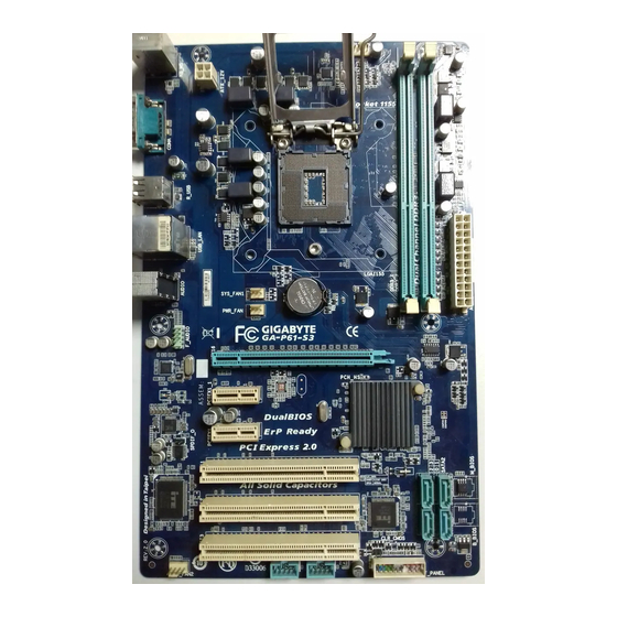
Page 5: Ga-P61-S3 Motherboard Layout
GA-P61-S3 Motherboard Layout KB_MS CPU_FAN ATX_12V LGA1155 R_USB USB_LAN AUDIO SYS_FAN1 PWR_FAN GA-P61-S3 PCIEX16 Atheros/Realtek GbE LAN PCIEX1_1 CODEC Intel PCIEX1_2 ® SPDIF_O SATA2 PCI1 PCI2 M_BIOS PCIe to PCI PCI3 Bridge B_BIOS CLR_CMOS SYS_FAN2 F_USB2 F_USB1 F_PANEL Box Contents... -
Page 6: Ga-P61-S3 Motherboard Block Diagram
GA-P61-S3 Motherboard Block Diagram 1 PCI Express x16 CPU CLK+/- (100 MHz) LGA1155 DDR3 1333/1066/800 MHz Dual Channel Memory PCIe CLK (100 MHz) PCI Express Bus 2 PCI Express x1 Dual BIOS 4 SATA 3Gb/s PCI Express Bus Intel 8 USB 2.0/1.1 ®... -
Page 7: Chapter 1 Hardware Installation
Chapter 1 Hardware Installation Installation Precautions The motherboard contains numerous delicate electronic circuits and components which can become damaged as a result of electrostatic discharge (ESD). Prior to installation, carefully read the user's manual and follow these procedures: Prior to installation, make sure the chassis is suitable for the motherboard. •... -
Page 8: 1-2 Product Specifications
Dual channel memory architecture Š Support for DDR3 1333/1066/800 MHz memory modules Š Support for non-ECC memory modules Š (Go to GIGABYTE's website for the latest supported memory speeds and memory modules.) Audio Realtek/VIA HD audio codec Š High Definition Audio Š... - Page 9 Operating Support for Microsoft Windows 7/Vista/XP Š ® System Form Factor ATX Form Factor; 30.5cm x 19.0cm Š * GIGABYTE reserves the right to make any changes to the product specifications and product-related information without prior notice. - 9 -...
-
Page 10: Installing The Cpu
Read the following guidelines before you begin to install the CPU: Make sure that the motherboard supports the CPU. • (Go to GIGABYTE's website for the latest CPU support list.) Always turn off the computer and unplug the power cord from the power outlet before installing the •... -
Page 11: Installing The Memory
• same capacity, brand, speed, and chips be used. (Go to GIGABYTE's website for the latest supported memory speeds and memory modules.) Always turn off the computer and unplug the power cord from the power outlet before installing the •... -
Page 12: Back Panel Connectors
Back Panel Connectors PS/2 Keyboard and PS/2 Mouse Port Use the upper port (green) to connect a PS/2 mouse and the lower port (purple) to connect a PS/2 keyboard. Serial Port Use the serial port to connect devices such as a mouse, modem or other peripherals. USB 2.0/1.1 Port The USB port supports the USB 2.0/1.1 specification. -
Page 13: Internal Connectors
Internal Connectors ATX_12V F_PANEL F_AUDIO CPU_FAN F_USB1/2 SYS_FAN1/2 SPDIF_O PWR_FAN CLR_CMOS SATA2 0/1/2/3 Read the following guidelines before connecting external devices: First make sure your devices are compliant with the connectors you wish to connect. • Before installing the devices, be sure to turn off the devices and your computer. Unplug the power •... - Page 14 1/2) ATX_12V/ATX (2x2 12V Power Connector and 2x12 Main Power Connector) With the use of the power connector, the power supply can supply enough stable power to all the components on the motherboard. Before connecting the power connector, first make sure the power supply is turned off and all devices are properly installed.
-
Page 15: Fan Headers
3/4/5) CPU_FAN/SYS_FAN1/SYS_FAN2/PWR_FAN (Fan Headers) The motherboard has a 4-pin CPU fan header (CPU_FAN), a 4-pin (SYS_FAN2) and a 3-pin (SYS_FAN1) system fan headers, and a 3-pin power fan header (PWR_FAN). Most fan headers possess a foolproof insertion design. When connecting a fan cable, be sure to connect it in the correct orientation (the black connector wire is the ground wire). -
Page 16: F_Panel (Front Panel Header)
7) F_PANEL (Front Panel Header) Connect the power switch, reset switch, speaker, chassis intrusion switch/sensor and system status indicator on the chassis to this header according to the pin assignments below. Note the positive and negative pins before connecting the cables. Message/Power/ Power Speaker... -
Page 17: Front Panel Audio Header
8) F_AUDIO (Front Panel Audio Header) The front panel audio header supports Intel High Definition audio (HD) and AC'97 audio. You may connect your chassis front panel audio module to this header. Make sure the wire assignments of the module connector match the pin assignments of the motherboard header. - Page 18 10) SPDIF_O (S/PDIF Out Header) This header supports digital S/PDIF Out and connects a S/PDIF digital audio cable (provided by expansion cards) for digital audio output from your motherboard to certain expansion cards like graphics cards and sound cards. For example, some graphics cards may require you to use a S/PDIF digital audio cable for digital audio output from your motherboard to your graphics card if you wish to connect an HDMI display to the graphics card and have digital audio output from the HDMI display at the same time.
-
Page 19: Battery
12) BAT (Battery) The battery provides power to keep the values (such as BIOS configurations, date, and time information) in the CMOS when the computer is turned off. Replace the battery when the battery voltage drops to a low level, or the CMOS values may not be accurate or may be lost. You may clear the CMOS values by removing the battery: Turn off your computer and unplug the power cord. -
Page 20: Chapter 2 Bios Setup
To access the BIOS Setup program, press the <Delete> key during the POST when the power is turned on. To upgrade the BIOS, use either the GIGABYTE Q-Flash or @BIOS utility. Q-Flash allows the user to quickly and easily upgrade or back up BIOS without entering the operating •... -
Page 21: The Main Menu
The Main Menu On the main menu of the BIOS Setup program, press arrow keys to move among the items and press <Enter> to accept or enter a sub-menu. Or you can use your mouse to select the item you want. (Sample BIOS Version: F1a) Setup Menus Enter Q-Flash... -
Page 22: M.i.t
M.I.T. Whether the system will work stably with the overclock/overvoltage settings you made is dependent on your overall system configurations. Incorrectly doing overclock/overvoltage may result in damage to CPU, chipset, or memory and reduce the useful life of these components. This page is for advanced users only and we recommend you not to alter the default settings to prevent system instability or other unexpected results. - Page 23 M.I.T. Current Status This screen provides information on CPU/memory frequencies/parameters. Advanced Frequency Settings CPU Clock Ratio & Allows you to alter the clock ratio for the installed CPU. The adjustable range is dependent on the CPU being installed. CPU Frequency &...
- Page 24 CPU Clock Ratio, CPU Frequency & The settings under the two items above are synchronous to that under the same items on the Advanced Frequency Settings menu. Internal CPU PLL Overvoltage & Enabled allows CPU PLL voltage to operate at a higher value. Disabled allows CPU PLL voltage to operate at default value.
- Page 25 CPU EIST Function & (Note) Enables or disables Enhanced Intel SpeedStep Technology (EIST). Depending on CPU loading, Intel EIST technology can dynamically and effectively lower the CPU voltage and core frequency to decrease average power consumption and heat production. Auto lets the BIOS automatically configure this setting. (Default: Auto) Bi-Directional PROCHOT &...
- Page 26 System Memory Multiplier, Memory Frequency(Mhz) & The settings under the two items above are synchronous to those under the same items on the Advanced Frequency Settings menu. Performance Enhance & Allows the system to operate at three different performance levels. Normal Lets the system operate at its basic performance level.
- Page 27 Advanced Voltage Settings CPU Vtt & Allows you to set CPU Vtt voltage. The default is Auto. DRAM Voltage & Allows you to set memory voltage. The default is Auto. PC Health Status - 27 -...
- Page 28 Reset Case Open Status & Disabled Keeps or clears the record of previous chassis intrusion status. (Default) Enabled Clears the record of previous chassis intrusion status and the Case Opened field will show "No" at next boot. Case Opened & Displays the detection status of the chassis intrusion detection device attached to the motherboard CI header.
-
Page 29: Miscellaneous Settings
Slope PWM & Allows you to control the CPU fan speed. This item is configurable only when CPU Fan Speed Control is set to Manual. Options are: 0.75 PWM value / C ~ 2.50 PWM value / 1st System Fan Speed Control (SYS_FAN1 Connector) &... -
Page 30: System
Isochronous Support & Determines whether to enable specific streams within the CPU and Chipset. This item is present only when you install a CPU that supports this feature. For more information about Intel CPUs' unique features, please visit Intel's website. (Default: Enabled) System This section provides information on your motherboard model and BIOS version. -
Page 31: Bios Features
Enables or disables Numlock feature on the numeric keypad of the keyboard after the POST. (Default: Enabled) Full Screen LOGO Show & Allows you to determine whether to display the GIGABYTE Logo at system startup. Disabled skips the GIGABYTE Logo when the system starts up. (Default: Enabled) PCI ROM Priority &... -
Page 32: Peripherals
Execute Disable Bit & (Note) Enables or disables Intel Execute Disable Bit function. This function may enhance protection for the computer, reducing exposure to viruses and malicious buffer overflow attacks when working with its supporting software and system. (Default: Enabled) Intel Virtualization Technology &... - Page 33 SATA Controller(s) (Intel H61 Chipset) & Enables or disables the integrated SATA controllers. (Default: Enabled) SATA Mode Selection (Intel H61 Chipset) & Allows you to decide whether to configure the SATA controllers integrated in the Intel H61 Chipset to AHCI mode.
-
Page 34: Power Management
Power Management AC BACK & Determines the state of the system after the return of power from an AC power loss. Memory The system returns to its last known awake state upon the return of the AC power. Always On The system is turned on upon the return of the AC power. -
Page 35: Save & Exit
& Determines whether to let the system consume less than 1W power in S5 (shutdown) state. (Default: Disabled) Note: When this item is set to Enabled, the following functions will become unavailable: PME event wake up, power on by mouse, power on by keyboard, and wake on LAN. High Precision Timer (Note) &... -
Page 36: Chapter 3 Drivers Installation
Load Optimized Defaults & Press <Enter> on this item and select Yes to load the optimal BIOS default settings. The BIOS default settings help the system to operate in optimum state. Always load the optimized defaults after updating the BIOS or after clearing the CMOS values. Boot Override &... -
Page 37: Regulatory Statements
"end of life" product. Restriction of Hazardous Substances (RoHS) Directive Statement GIGABYTE products have not intended to add and safe from hazardous substances (Cd, Pb, Hg, Cr+6, PBDE and PBB). The parts and components have been carefully selected to meet RoHS requirement. Moreover, we at GIGABYTE are continuing our efforts to develop products that do not use internationally banned toxic chemicals. - Page 38 - 38 -...
- Page 39 - 39 -...
- Page 40 Tech. and Non-Tech. Support (Sales/Marketing) : http://ggts.gigabyte.com.tw WEB address (English): http://www.gigabyte.com WEB address (Chinese): http://www.gigabyte.tw You may go to the GIGABYTE website, select your language in the language list on the top right corner of the website. GIGABYTE Global Service System •...
Need help?
Do you have a question about the GA-P61-S3 and is the answer not in the manual?
Questions and answers