Table of Contents
Advertisement
Available languages
Available languages
Owner's Manual
®
T TI
TILL
800 Series
24 Inch Tine Width
Model No.
917.299110
• Espa5ol,
p. 19
This product has a low emission
engine
which
operates
differently
from
previously
built
engines.
Before
start the
you
engine,
read and understand
this Owner's
Manual.
IMPORTANT:
Read and follow all Safety
Rules and Instructions
before
operating
this equipment,
Sears, Roebuck
and Co., Hoffman
Estates,
IL 60179 U.S.A.
Visit our Craftsman
website:www.sears.com/craftsman
Advertisement
Table of Contents

Related Manuals for Craftsman 917.299110


Summary of Contents for Craftsman 917.299110
- Page 1 Before start the engine, read and understand this Owner's Manual. IMPORTANT: Read and follow all Safety Rules and Instructions before operating this equipment, Sears, Roebuck and Co., Hoffman Estates, IL 60179 U.S.A. Visit our Craftsman website:www.sears.com/craftsman...
- Page 2 If this CraftsmanTiller is used for commercial or rental purposes, this Warranty ap- plies for only thirty (30) days from the date of purchase. Warranty service is available by returningthe craftsman power mower to the nearest sears service center/departmentin the united states. This warranty applies only while this product is in use in the united states.
- Page 3 • Use extension cords and receptacles • Do not overload the machine capacity as specified by the manufacturer for all by attempting to till too deep at too fast units with electric drive motors or elec- a rate. tric starting motors.
- Page 4 (Gap: .030") RC12YC AGREEMENTS Congratulations on making a smart pur- CONGRATULATIONS on your purchase chase. Your new Craftsman® product of a Sears Tiller. It has been designed, designed and manufactured for years of engineered and manufactured to give you dependable operation.
-
Page 5: Tiller Maintenance
These accessories were available when the tiller was produced. They are also available at most Sears retail outlets and service centers. Some of these accessories may not apply to your tiller. ENGINE SPARK PLUG MUFFLER AIR FILTER GAS CAN ENGINE OIL STABILIZER TILLER MAINTENANCE BELT... - Page 6 Your new tiller has been assembled at the factory with the exception of those parts left unassembled for shipping purposes. To ensure safe and proper operation of your tiller all parts and hardware you assemble must be tightened securely. Use the correct tools as necessary to insure...
-
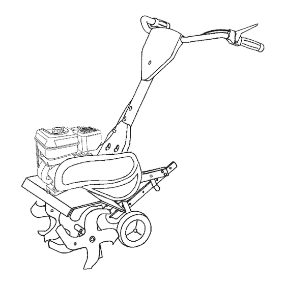
Page 7: Know Your Tiller
KNOW YOUR TILLER READ THIS OWNER'S MANUAL SAFETY RULES BEFORE OPERATING YOUR TILLER Compare the illustrations with your tiller to familiarize yourself with the locations of vari- ous controls and adjustments. Save this manual for future reference. F N R TILLING FORWARD NEUTRAL... - Page 8 The operation of any tiller can result in foreign objects thrown into the eyes, which can result in severe eye damage. Always wear safety glasses or eye shields before starting your tiller and while tilling. We recommend standard safety glasses or a wide vision safety mask worn...
- Page 9 4. Tilt tiller back on its wheels and then START ENGINE re-level. Ai_CAUTION: Keep tine control in "OFF" 5. With engine level, refill to point of over- position when starting engine. flowing if necessary. Replace oil filler When starting engine for the first time or plug.
- Page 10 BREAKING IN YOUR TILLER * You will find tilling much easier if you leave a row untilled between passes. Break-in your belt(s), pulleys and tine con- Then go back between tilled rows There trol before you actually begin tilling. are two reasons for doing this.
-
Page 11: Lubrication Chart
SCHEDULE __.,_ FILL IN DATES MAINTENANCE SERVICE DATES AS YOU COMPLETE /4bz,_/ REGULAR SERVICE Check Engine Oil Level Change Engine Oil 1_1,2 Oil Pivot Points Inspect Spark Arrester / Muffler Inspect Air Screen Clean or Replace Air Cleaner Cartridge Clean Engine Cylinder Fins Replace Spark... - Page 12 Refill engine with oil. See "FILL ,_CAUTION:Disconnect spark plug ENGINE WITH OIL" in the Operation wire before performing any maintenance section of this manual. (except carburetor adjustment) to prevent accidental starting of engine. Prevent fires! Keep the engine free of grass, leaves, spilled...
- Page 13 COOLING SYSTEM SPARK PLUG Your engine is air cooled. For proper Replace spark plugs at the beginning gine performance and long life keep your each tilling season or after every 50 hours engine clean. of use, whichever comes first. Spark plug Clean air screen...
- Page 14 MID-WIDTH TILLING - 22" PATH _CAUTION: Disconnect spark plug wire from spark plug and place wire where it Assemble holes '_' in tine hubs to holes cannot come into contact with plug. "C" in tine shaft. TILLER TO ADJUST HANDLE HEIGHT Factory assembly...
- Page 15 FINAL CHECK "ON" POSITION TO REPLACE V-BELT With tine control "ON" (held down to Replace V-belt if it has stretched consider- handle) push down on handle to raise ably or if it has cracks or frayed edges. tines off the ground. Belt guard must be removed...
- Page 16 Immediately prepare your tiller for storage NOTE: Fuel stabilizer is an acceptable at the end of the season or if the unit will alternative in minimizing the formation not be used for 30 days or more. fuel gum deposits during storage.
-
Page 17: Troubleshooting
TROUBLESHOOTING CHART: See appropriate section in manuaJ unJess directed to Sears service center PROBLEM CAUSE CORRECTION Will not start Out of fuel. Fill fuel tank. See "TO START ENGINE" Engine not "CHOKED" properly. in the Operation section. Wait several minutes before Engine flooded. -
Page 18: Need More Help
TROUBLESHOOTING CHART: See appropriate section in manual unless directed to Sears service center CAUSE CORRECTION PROBLEM Engine Low oil level/dirty oil. Check oil level/change oil. overheats Dirty engine air screen. Clean engine air screen. Dirty engine. Clean cylinder fins, airscreen, muffler area. - Page 19 • Si la Cultivadora Craftsman se usa para fines de arriendo, esta garantfa se aplica solamente treinta (30) dias a partir de la fecha de compra. El Servicio de Garantia esta disponible...
-
Page 20: Mantenimiento
OPERAClON • Use solamente accesorios y aditamentos para la cultivadora aprobados por el fabrican- No ponga ni las manos ni los pies cerca o debajo de las piezas rotatorias. • Nunca opere la cultivadora sin buena visibili- • Tenga mucho cuidado cuando opere o cruce dad o luz. -
Page 21: Especificaciones
LA REPARAClON Capacidad 3 Cuartos Congratulaciones por su buena compra. Gasolina: Sin plomo, Regular Su nuevo producto Craftsman<,_, est& diseflado Aceite (API-SG-SL): SAE 30 (Sobre 32°F) y fabricado para funcionar de modo fiable por SAE 5W-30 (Capacidad: 20 oz.) (Debajo 32°F) - Page 22 Estos accesorios estaban disponibles cuando se produjo la cultivadora. Tambien est&n disponibles en la mayorfa de las tiendas de Sears y en los centros de servicio. Algunos de estos accesorios tal vez no se apliquen a su cultivadora. MOTOR BUJ|A SILENCIADOR FILTRO DE AIRE...
-
Page 23: Herramientas Necesarias Para El Montaje
Su cultivadora nueva ha side montada en la f&brica, con la excepci6n de aquellas partes que se dejaron sin montar per razones de envio. Para asegurarse que la cultivadora operara en forma segura y adecuada, todas las partes y los artfculos de ferreteria que monte tienen que estar apre- tados en forma segura. - Page 24 CONOZCA SU CULTmVADORA LEA ESTE MANUAL DEL DUEI_IO Y LAS REGLAS DE SEGURIDAD ANTES DE OPERAR CUTIVADORA Compare las ilustraciones con su cultivadora para familiarizarse con la ubicaci6n de los diversos controles y ajustes. Guarde este manual para referencia en el futuro. Estos sirnbolos pueden apateser eobre eu cultivadora en la Iitetatura...
- Page 25 La operaci6n de cualquier cultivadora puede hacer que salten objetos extrahos dentro de sus ojos, Io que puede producir dahos graves en estos. Siempre use anteojos de seguridad o protecciones para los ojos antes de hacer arrancar su cultivadora mientras este labrando con ella. Recomendamos el uso de la m&scara de seguridad de visi6n amplia, para use sobre los espejuelos o anteojos de seguridad est&ndar.
- Page 26 5. Conel motornivelado, v uelvaa Ilenarlo PARA HACER ARRANCAR EL MOTOR hastael puntodederramarse, si esnecesa- _,PRECAUCl6N: Mantenga la barra de rio.Vuelva a colocareltap6ndeldep6sito control de la impulsi6n en la posici6n "DESEN- de relleno de aceite. GANCHADO" cuando haga arrancar el motor. •...
- Page 27 RODAJE DE SU CULTIVADORA • Va a descrubrir que el labrado se faciNta si deja una fila sin labrar entre las pasadas. Use su(s) correa(s), las poleas y el control de Entonces vuelva de nuevo entre las filas de los brazos antes de empezar a labrar. cultivo.
-
Page 28: Programa De Mantenimiento
kS/L/ PROGRAMA MANTENIMIENTO QUE COMPLETE #/_._/'4/Z0_/40_/©_/ SERVICIO REGULAR /_'_'/©_"/O_'/©_'J/ FECHAS SERVlCIO Revisar el nivel del aceite del motor Cambiar el aceite del motor Aceitar los puntos de pivote Inspeccionar el supresor del silenciador Inspeccionar la rejilla de aire Limpiar/cambiar el cartucho del filtro de aire Limpiar las aletas del cilindro del motor... - Page 29 Despu6s de que el aceite se haya drenado _,PRECAUCI6N: Desconecte el alambre de completamente, vuelva a colocar el tap6n la bujia antes de dar mantenimiento (excepto del drenaje del aceite y apri6telo en forma por el ajuste del carburador) para evitar que el segura.
- Page 30 BUJiA Aletas del cilindor Cambie las bujias al comienzo de cada temporada de cuitivo, o despues de 50 horas Silenciador de uso, Io que suceda primero. El tipo de bujia y la abertura aparece en las "ESPECIFICACIONES DEL PRODUCTO" Caja del la p&gina 21 de este manual.
- Page 31 CULTIVO/LABRADO ESTRECHO - PASO DE Si los brazos no rotan, el alambre interior del cable de control est& demasiado suelto. 12-3/4" Suelte la abrazadera del cable y empuje el • Remueva los brazos exteriores. cable hacia arriba para remover la soltura y vuelva a apretar la abrazadera.
- Page 32 PARA CAMBIAR LA CORREA V MOTOR Cambie la correa V si se ha estirado consid- El mantenimiento, la reparaci6n, o el reemplazo erablemente o si est& partida o si los bordes de cualquier dispositivos o sistemas del control est&n desgastados. de la emisi6n, los cuales sean hechos al costo La protecci6n de la correa tiene que del cliente, pueden ser realizados por cualquier...
- Page 33 AVlSO: El estabilizador de combustible es una Inmediatamente prepare su cultivadora para el almacenamiento al final de la temporada o si la alternativa aceptable para reducir a un minimo unidad no se va a usar por 30 dias o m&s. la formaci6n de dep6sitos de goma en el com- _PREOAUOI6N: Nunca almacene la cultiva-...
- Page 34 IDENTIFICACK)N DE PROBLEMAS: Vea la secci6n apropiada en el manual a menos que est6 dirigido a un centro de servicio Sears. CORRECCION CAUSA PROBLEMA 1. Sin combustible. NO arranca 1. Llene el estanque de combustible. 2. Motor sin la "ESTRANGU- 2.
- Page 35 IDENTIFICACION DE PROBLEMAS: Vea la secci6n apropiada en el manual a menos que eet6 dirigido a un centro de eervicio Sears. PROBLEMA CAUSA CORRECCION El motor ee 1. Revise el nivel del aceite/cambie 1. Nivel del aceite bajo/aceite calienta dem sucio.
- Page 36 TILLER = = MODEL NUMBER 917.299110 HANDLES 13_. • handle assy 99 9epic KEY PART PART DESCRIPTION DESCRIPTION 137118X023 Panel, Control 72010520 Bolt 5/16-18 x 2-1/2 165787 Grip, Handle 73970500 Locknut, Flange 5/16-18 98000129 Nut, Flange 417465 Assembly, Handle Column STD533107 Bolt, Carriage 5/16-18 x 3/4...
- Page 37 TILLER = = MODEL NUMBER BELT GUARD AND PULLEY ASSEMBLY "-.. /-{t belt guard PART PART DESCRIPTION DESCRIPTION 23230506 Screw Set 5/16-18 x 3/8 Patch 12000028 Ring, Retainer 130812 Sheave, Engine 151223 Sheave, Transmisison 86777 Screw, Tap Hex Head 12000036 Ring, Klip 74610812 Bolt, Hex Head 1/2-20 x 3/4...
- Page 38 TILLER - - MODEL NUMBER 917.299110 WHEEL AND DEPTH STAKE ASSEMBLY wheel d.stake2 KEY PART PART DESCRIPTION DESCRIPTION 9194R Pin, Clevis 5388J Spring, Stake 74760520 Bolt, Hex Head 5/16-18 x 1-1/4 121117X Bolt, Shoulder 9188R Wheel STD523107 Bolt, Hex Head 5/16-18 x 3/4 73220500 STD551037 Washer...
-
Page 39: Tine Assembly
TILLER = = MODEL NUMBER 917.299110 TINE ASSEMBLY tine_ipb_3 KEY PART KEY PART DESCRIPTION DESCRIPTION 156926 Tine, Outer, R.H. 156925 Tine, Outer, L.H. 3146R 4929H Pin, Clevis Retainer, Spring Zinc 156924 Tine, Inner, R.H. NOTE: All component dimensions given in U.S.inches. Tine, Inner, LH. - Page 40 TILLER - - MODEL NUMBER 917.299110 TRANSMISSION transmission PART PART DESCRIPTION DESCRIPTION Bolt, Hex 5/16-18 x 1-1/2 Gr. 2 73970500 74760524 Nut, Lock Hex Flange 5/16-18 unc 19091412 STD523732 Bolt, Fin, Hex 3/8-16 x 3-1/4 Washer 9/32 x 7/8 x 12 Ga. 19092016 STD551037 Washer...
- Page 41 TILLER - - MODEL NUMBER 917.299110 DECALS PART DESCRIPTION 418932 Decal, Logo 418931 Decal, Tine Shield 137539 Decal, Cntrl Pnl Inst. Decal, Hand Placement 120431X 417657 Decal, Engine 162215 Decal, Tine Shield Warning 417544 Decal, Engine B&S Intek 411816 Decal, Rewind Intek 120075X Decal, Warning, Rotating Tines 419702...
- Page 42 TILLER - - MODEL NUMBER 917.299110 ENGINE, BRIGGS & STRATTON - MODEL NUMBER 157102, TYPE NO. 1013-E8 15A® 718 _::> il 330 REPAIR MANUAL 42 _...
- Page 43 TILLER = - MODEL NUMBER 917.299110 ENGINE, BRIGGS & STRATTON -= MODEL NUMBER 157102, TYPE NO. 1013=E8 633A Q 365_ " 276Q 977 CARBURETOR GASKET 163% 633AQ 633 @ 121 CARBURETOR OVERHAUL lo_ 127G633_ 633AQ 358 ENGINE GASKET SET 1022...
- Page 44 TILLER = = MODEL NUMBER 917.299110 ENGINE, BRIGGS & STRATTON -= MODEL NUMBER 157102, TYPE NO. 1013=E8 971_...
- Page 45 TILLER = = MODEL NUMBER 917.299110 ENGINE, BRIGGS & STRATTON -= MODEL NUMBER 157102, TYPE NO. 1013=E8 1211 689 © 456 _ { 1036 EMiSSiONS LABEL ] i 1329 REPLACEMENT ENGINE i 1005 1095 VALVE GASKET 1022_...
- Page 46 TILLER = = MODEL NUMBER 917.299110 ENGINE, BRIGGS & STRATTON -= MODEL NUMBER 157102, TYPE NO. 1013=E8 PART PART DESCRIPTION DESCRIPTION 794188 Cylinder Assembly 696024 435 Gasket-Air Cleaner 399269 Kit-Bushing/Seal (Magneto Side) 692317 Connector-Hose 299819s ,Seal-Oil (Magneto Side) 791874 Line-Fuel 791720 Head-Cylinder 699479...
- Page 47 TILLER = = MODEL NUMBER 917.299110 ENGINE, BRIGGS & STRATTON -= MODEL NUMBER 157102, TYPE NO. 1013=E8 PART DESCRIPTION 694257 Spacer Deflector-Muffler 393757 690661 Screw (Muffler Deflector) 793369 Screw (Breather Passage Cover) 691855 Spring-Friction 690572 Spring-Detent 690959 Pin-Locating 695087 Gear-Timing 692564 Retainer-E Ring Gear-Idler...
- Page 48 NEED MORE HELP? Youq,/find tee answeI aml moie on ma_agem)]homemom ,,oo for f_ee! Find this and aLLyour other product manuaLs onLine. : _ Get answers from our team of home experts. Get a persona[ized maintenance pLan for your home. Find informaL_on and tooLs to heLp with home projecLs, iiiiiill iI ii_ii_! __ _ _`_`_`_`_`_`_`_`_`_`_`_`_`_`_`_`_`_`_`_`_`_`_`_`_`_`_`_`_` _iiii_i_ii...
Need help?
Do you have a question about the 917.299110 and is the answer not in the manual?
Questions and answers
i need a new carb and trying to find the correct part # for it
The correct carburetor part number for Craftsman model 917.299110 is 699484.
This answer is automatically generated