Intel DX58OG Product Manual
Desktop board
Hide thumbs
Also See for DX58OG:
- Specification (6 pages) ,
- Technical product specification (91 pages) ,
- Product manual (88 pages)
Table of Contents
Advertisement
Advertisement
Table of Contents

Subscribe to Our Youtube Channel
Related Manuals for Intel DX58OG


Summary of Contents for Intel DX58OG
- Page 1 Intel® Desktop Board DX58OG Product Guide Order Number: G13831-001...
-
Page 2: Revision History
Intel may make changes to specifications and product descriptions at any time, without notice. Intel Desktop Board DX58OG may contain design defects or errors known as errata which may cause the product to deviate from published specifications. Current characterized errata are available on request. -
Page 3: Intended Audience
The suitability of this product for other PC or embedded non-PC applications or other environments, such as medical, industrial, alarm systems, test equipment, etc. may not be supported without further evaluation by Intel. Document Organization The chapters in this Product Guide are arranged as follows:... - Page 4 Intel Desktop Board DX58OG Product Guide Terminology The table below gives descriptions of some common terms used in the product guide. Term Description Gigabyte (1,073,741,824 bytes) Gigahertz (one billion hertz) Kilobyte (1024 bytes) Megabyte (1,048,576 bytes) Megabit (1,048,576 bits) Megahertz (one million hertz)
-
Page 5: Table Of Contents
Contents 1 Desktop Board Features Supported Operating Systems................11 Desktop Board Components.................12 Processor......................14 Main Memory.....................15 ® Intel X58 Express Chipset..................16 Audio Subsystem ....................16 LAN Subsystem ....................17 USB 2.0 Support ....................18 Serial ATA......................18 Legacy I/O ......................18 Expandability.....................18 BIOS ........................19 Serial ATA and IDE Auto Configuration............19 PCI and PCI Express* Auto Configuration ............19... - Page 6 Flash Memory Update Utility or the ISO Image BIOS Update File ................64 Obtaining the BIOS Update File ..............64 Updating the BIOS with the Intel Flash Memory Update Utility......65 Updating the BIOS with the ISO Image BIOS Update File .........65 Recovering the BIOS ...................66...
- Page 7 Matrix Storage Technology ........67 Configuring the BIOS ..................67 Creating Your RAID Set ................67 Loading the Intel Matrix Storage Technology RAID Drivers and Software ....68 Setting Up a “RAID Ready” System ...............68 Configuring for External RAID Using Marvell* Storage Technology......69 Configuring the BIOS ..................69 Creating Your RAID Set ................69...
- Page 8 28. Removing the Battery ...................60 29. Installing the WiFi/Bluetooth Module ...............62 30. POST Code LED Display .................73 31. Intel Desktop Board DX58OG China RoHS Material Self Declaration Table .....82 Tables 1. Feature Summary..................9 2. Intel Desktop Board DX58OG Components ............13 3.
-
Page 9: Desktop Board Features
1 Desktop Board Features ® This chapter briefly describes the features of Intel Desktop Board DX58OG. Table 1 summarizes the major features of the Desktop Board. Table 1. Feature Summary ATX (304.80 millimeters [12.00 inches] x 243.84 millimeters Form Factor [9.60 inches]) - Page 10 Intel Desktop Board DX58OG Product Guide Table 1. Feature Summary (continued) ® LAN Support Gigabit (10/100/1000 Mb/s) LAN subsystem using the Intel 82567L Gigabit Ethernet Controller ® BIOS • Intel Platform Innovation Framework for extensible firmware interface • 16 Mb symmetrical flash memory device •...
-
Page 11: Supported Operating Systems
Desktop Board Features Supported Operating Systems • Microsoft Windows* 7 Ultimate 64-bit edition • Microsoft Windows 7 Ultimate 32-bit edition • Microsoft Windows 7 Professional 64-bit edition • Microsoft Windows 7 Professional 32-bit edition • Microsoft Windows 7 Home Premium 64-bit edition •... -
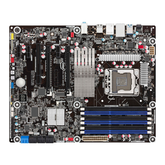
Page 12: Desktop Board Components
Intel Desktop Board DX58OG Product Guide Desktop Board Components Figure 1 shows the approximate location of the major components on Intel Desktop Board DX58OG. Figure 1. Intel Desktop Board DX58OG Components... - Page 13 Desktop Board Features Table 2. Intel Desktop Board DX58OG Components Label Description Front panel audio header PCI Express 1.1 x1 connector PCI Express 1.1 x1 connector PCI bus connector (x8 electrical) PCI Express 2.0 x16 connector PCI Express 1.1 x1 connector PCI Express 2.0 x16 connector...
-
Page 14: Processor
Intel Desktop Board DX58OG Product Guide Online Support For more information on Intel Desktop Board DX58OG consult the following online resources: • Intel Desktop Board DX58OG http://www.intel.com/products/motherboard/index.ht • Desktop Board Support http://www.intel.com/p/en_US/support?iid=hdr+supp • Available configurations for Intel http://ark.intel.com Desktop Board DX58OG •... -
Page 15: Main Memory
Main Memory NOTE ® To be fully compliant with all applicable Intel SDRAM memory specifications, the board should be populated with DIMMs that support the Serial Presence Detect (SPD) data structure. If your memory modules do not support SPD, you will see a notification to this effect on the screen at power up. -
Page 16: Intel X58 Express Chipset
Go to the following link or pages for more information about: • The location of the onboard audio headers, Figure 23 on page 46 • The signal names for the Intel High Definition Audio front panel header, page 47 • The back panel audio connectors, Figure 24 on page 51... -
Page 17: Lan Subsystem
• RJ-45 LAN connector with integrated status LEDs The subsystem features: • CSMA/CD protocol engine • LAN connect interface between ICH10R and the Intel 82567L Gigabit Ethernet LAN Controller • PCI bus power management Go to the following link for information about LAN software and drivers: http://www.intel.com/products/motherboard/index.htm... -
Page 18: Usb 2.0 Support
For information on configuring your system for RAID using Intel Matrix Storage Technology see Chapter 4. Legacy I/O Intel Desktop Board DX58OG includes an I/O controller that provides the following legacy I/O features: • Consumer Infrared (CIR) support • Low pin count (LPC) interface •... -
Page 19: Bios
Desktop Board Features BIOS The BIOS provides the Power-On Self-Test (POST), the BIOS Setup program, and the PCI/PCI Express and IDE auto-configuration utilities. The BIOS is stored in the Serial Peripheral Interface (SPI) Flash device. The BIOS can be updated by following the instructions on page 63 in Chapter 3. Serial ATA and IDE Auto Configuration If you install a Serial ATA or IDE device (such as a hard drive) in your computer, the auto-configuration utility in the BIOS automatically detects and configures the device... -
Page 20: Back To Bios Button
Figure 3. Location of the Back to BIOS Button Hardware Management The hardware management features of Intel Desktop Board DX58OG enable the board to be compatible with the Wired for Management (WfM) specification. The board has several hardware management features including the following: •... -
Page 21: Hardware Monitoring And Fan Speed Control
® Intel Precision Cooling Technology Intel Precision Cooling Technology automatically adjusts processor fan speed based on the processor temperature and adjusts chassis fan speeds based on the internal system temperature. Chassis Intrusion The board supports a chassis security feature that detects if the chassis cover has been removed. -
Page 22: Hardware Support
Intel Desktop Board DX58OG Product Guide Hardware Support Power Connectors ATX12V-compliant power supplies can turn off the computer power through system control. When an ACPI-enabled computer receives the correct command, the power supply removes all non-standby voltages. When resuming from an AC power failure, the computer returns to the power state it was in before power was interrupted (either on or off). -
Page 23: Instantly Available Pc Technology
Desktop Board Features Instantly Available PC Technology CAUTIONS For Instantly Available PC technology, the 5 V standby line for the power supply must be capable of delivering adequate +5 V standby current. Failure to provide adequate standby current when using this feature can damage the power supply and/or effect ACPI S3 sleep state functionality. -
Page 24: Wake From Usb
Intel Desktop Board DX58OG Product Guide Figure 4. Location of the Standby Power Indicator For more information on standby current requirements for the Desktop Board, refer to the Technical Product Specification at h ttp://www.intel.com/products/motherboard/index.htm Wake from USB NOTE Wake from USB requires the use of a USB peripheral that supports Wake from USB and an operating system that supports Wake from USB. -
Page 25: Wake From Consumer Ir
Desktop Board Features Wake from Consumer IR Consumer IR device activity wakes the computer from an ACPI S3, S4, or S5 state. Onboard Power and Reset Switches The board contains the following lighted button switches that can be used to control board operation: •... -
Page 26: Diagnostic/Status Leds
Intel Desktop Board DX58OG Product Guide Diagnostic/Status LEDs The Desktop Board provides 11 LEDs that allow you to monitor the board’s progress through the BIOS POST along with other board activities and conditions (see Figure 6). Figure 6. Location of the Diagnostic/Status LEDs... -
Page 27: Diagnostic Leds
Desktop Board Features Diagnostic LEDs At initial power on, the eight diagnostic LEDs are off. When the BIOS starts an activity such as memory initialization, the corresponding LED starts flashing. Once the activity has completed, the LED will remain on. Table 4 lists the LEDs and describes their function. -
Page 28: Cpu And Vr Hot Leds
Intel Desktop Board DX58OG Product Guide CPU and VR Hot LEDs The following red LEDs (see Figure 6) indicate the status of the processor and the board’s voltage regulation circuitry: • The CPU LED (Figure 6, I) indicates an elevated temperature on the processor that could affect performance. -
Page 29: Installing And Replacing Desktop Board Components
2 Installing and Replacing Desktop Board Components This chapter tells you how to: • Install the I/O shield • Install and remove the Desktop Board • Install and remove a processor • Install and remove memory • Install and remove a PCI Express x16 card •... -
Page 30: Installation Precautions
Intel Desktop Board DX58OG Product Guide Installation Precautions When you install and test the Intel Desktop Board, observe all warnings and cautions in the installation instructions. To avoid injury, be careful of: • Sharp pins on connectors • Sharp pins on printed circuit assemblies •... -
Page 31: Installing The I/O Shield
Installing and Replacing Desktop Board Components Installing the I/O Shield The Desktop Board comes with an I/O shield. When installed in the chassis, the shield blocks radio frequency transmissions, protects internal components from dust and foreign objects, and promotes correct airflow within the chassis. Install the I/O shield before installing the Desktop Board in the chassis. -
Page 32: Installing And Removing The Desktop Board
Refer to your chassis manual for instructions on installing and removing the Desktop Board. Figure 8 shows the location of the mounting screw holes for Intel Desktop Board DX58OG. Figure 8. Intel Desktop Board DX58OG Mounting Screw Hole Locations... -
Page 33: Installing And Removing A Processor
Installing and Replacing Desktop Board Components Installing and Removing a Processor Instructions on how to install the processor on the Desktop Board are given below. Installing a Processor CAUTION Before installing or removing a processor, make sure the AC power has been removed by unplugging the power cord from the computer;... -
Page 34: Lift The Load Plate
Intel Desktop Board DX58OG Product Guide 3. Lift the load plate as shown in Figure 10, A. Do not touch the socket contacts. Figure 10. Lift the Load Plate... -
Page 35: Remove The Processor From The Protective Processor Cover
Installing and Replacing Desktop Board Components 4. Remove the processor from the protective processor cover. Hold the processor only at the edges, being careful not to touch the bottom of the processor (see Figure 11). Do not discard the protective processor cover. Always replace the processor cover if the processor is removed from the socket. -
Page 36: Close The Load Plate
Intel Desktop Board DX58OG Product Guide 7. Close the load plate (Figure 13, A, B). As the load plate is closed, the socket cover (Figure 13, C) will pop off as shown. After the load plate is closed, engage the socket lever (Figure 13, D) under the latch. -
Page 37: Installing The Processor Fan Heat Sink
Installing and Replacing Desktop Board Components Installing the Processor Fan Heat Sink Intel Desktop Board DX58OG has mounting holes for a processor fan heat sink. For instructions on how to attach the processor fan heat sink to the Desktop Board, refer to the boxed processor manual or boxed thermal solution manual. -
Page 38: Removing The Processor
For instructions on how to remove the processor fan heat sink and processor, refer to the processor installation manual. Installing and Removing Memory Intel Desktop board DX58OG has six 240-pin DDR3 DIMM sockets arranged in three channels (A, B, and C). Each channel has two sockets as shown in the following illustrations. -
Page 39: Installing Dimms
Installing and Replacing Desktop Board Components Installing DIMMs To make sure you have the correct DIMM, place it on the illustration of the DDR3 DIMM in Figure 17. All the notches should match with the DDR3 DIMM. Figure 17. Use DDR3 DIMMs... -
Page 40: Installing A Dimm
Intel Desktop Board DX58OG Product Guide NOTE Using a DIMM with a voltage rating higher than 1.65 V may damage the processor. To install a DIMM, follow these steps: 1. Observe the precautions in "Before You Begin" on page 29. -
Page 41: Removing Dimms
Installing and Replacing Desktop Board Components Removing DIMMs To remove a DIMM, follow these steps: 1. Observe the precautions in "Before You Begin" on page 29. 2. Turn off all peripheral devices connected to the computer. Turn off the computer. 3. -
Page 42: Removing A Pci Express X16 Add-In Card
Intel Desktop Board DX58OG Product Guide Figure 19. Installing a PCI Express x16 Card Removing a PCI Express x16 Add-in Card Follow these instructions to remove a PCI Express x16 card from a connector: 1. Observe the precautions in "Before You Begin" on page 29. -
Page 43: Installing Linked Pci Express X16 Graphics Cards
Installing and Replacing Desktop Board Components Figure 20. Removing a PCI Express x16 Card Installing Linked PCI Express x16 Graphics Cards The Desktop Board supports the use of linked PCI Express x16 graphics cards with Nvidia* SLI* technology and ATI* CrossFireX* technology. When installing linked graphics cards in the PCI Express x16 connectors, refer to the card manufacturer’s instructions to determine correct card placement and interconnection. -
Page 44: Installing Linked Pci Express Graphics Cards
Intel Desktop Board DX58OG Product Guide 3. Place the second card in the secondary PCI Express x16 connector (Figure 21, A) and press down on the card until it is completely seated in the connector and the card retention notch on the card snaps into place around the retention mechanism pin on the connector. -
Page 45: Connecting The Serial Ata (Sata) Cables
Installing and Replacing Desktop Board Components Connecting the Serial ATA (SATA) Cables SATA cables support the Serial ATA protocol. Each cable can be used to connect one internal SATA drive to the Desktop Board. The blue connectors support SATA 6 Gb/s and lower transfer rates and the black connectors support SATA 3 Gb/s and lower transfer rates. -
Page 46: Connecting To The Internal Headers
Intel Desktop Board DX58OG Product Guide Connecting to the Internal Headers Before connecting cables to any of the internal headers, observe the precautions in “Before You Begin” on page 29. Figure 23 shows the location of the internal headers on Intel Desktop Board DX58OG. -
Page 47: Front Panel Audio Header
Installing and Replacing Desktop Board Components Front Panel Audio Header Figure 23, A shows the location of the front panel audio header. Table 5 shows the pin assignments and signal names for the front panel audio header. Table 5. Front Panel Audio Header Signal Names Signal Name Signal Name PORT 1L... -
Page 48: Consumer Ir (Cir) Headers
Intel Desktop Board DX58OG Product Guide Consumer IR (CIR) Headers The Desktop Board has two CIR headers: the input or receiver header (Figure 23, E) and the output or emitter header (Figure 23, C). The receiver header consists of a filtered translated infrared input compliant with Microsoft CIR specifications and a “learning”... -
Page 49: Chassis Intrusion Header
Installing and Replacing Desktop Board Components Chassis Intrusion Header Figure 23, D shows the location of the chassis intrusion header. This header can be connected to a mechanical switch on the chassis to detect if the chassis cover is removed. Table 9 shows the pin assignments and signal names for the chassis intrusion header. -
Page 50: Alternate Front Panel Power Led Header
Intel Desktop Board DX58OG Product Guide Alternate Front Panel Power LED Header Figure 23, G shows the location of the alternate front panel power LED header. Pins 1 and 3 of this header duplicate the signals on pins 2 and 4 of the front panel header. If your chassis has a three-pin power LED cable, connect it to this header. -
Page 51: Connecting To The Audio System
Installing and Replacing Desktop Board Components Connecting to the Audio System ® After installing the RealTek audio driver from the Intel Express Installer DVD-ROM, the multi-channel audio feature can be enabled. Figure 24 shows the back panel audio connectors. The default connector assignments are shown in the table. -
Page 52: Connecting Chassis Fan And Power Supply Cables
Intel Desktop Board DX58OG Product Guide Connecting Chassis Fan and Power Supply Cables Connecting Chassis Fan Cables Connect chassis fan cables to the chassis fan headers on the Desktop Board. Figure 25 shows the location of the chassis fan headers. -
Page 53: Connecting Power Supply Cables
Installing and Replacing Desktop Board Components Connecting Power Supply Cables Figure 26 shows the location of the power connectors. CAUTION Failure to use an appropriate power supply and/or not connecting the 12 V (Figure 26, A) power connector to the Desktop Board may result in damage to the board or the system may not function properly. -
Page 54: Setting The Bios Configuration Jumper
Intel Desktop Board DX58OG Product Guide Setting the BIOS Configuration Jumper NOTE Always turn off the power to the computer before moving the jumper. Moving the jumper with the power on may result in unreliable computer operation. Figure 27 shows the location of the Desktop Board’s BIOS configuration jumper block. -
Page 55: Clearing Passwords
Installing and Replacing Desktop Board Components Table 13. Jumper Settings for the BIOS Setup Program Modes Jumper Setting Mode Description Normal (default) (1-2) The BIOS uses the current configuration and passwords for booting. Configure (2-3) After the Power-On Self-Test (POST) runs, the BIOS displays the Maintenance Menu. -
Page 56: Replacing The Battery
Intel Desktop Board DX58OG Product Guide 12. To restore normal operation, place the jumper on pins 1-2 as shown below. 13. Replace the cover, plug in the computer, and turn on the computer. Replacing the Battery A coin-cell battery (CR2032) powers the real-time clock and CMOS memory. When the computer is not plugged into a wall socket, the battery has an estimated life of three years. - Page 57 Installing and Replacing Desktop Board Components VARO Räjähdysvaara, jos pariston tyyppi on väärä. Paristot on kierrätettävä, jos se on mahdollista. Käytetyt paristot on hävitettävä paikallisten ympäristömääräysten mukaisesti. VORSICHT Bei falschem Einsetzen einer neuen Batterie besteht Explosionsgefahr. Die Batterie darf nur durch denselben oder einen entsprechenden, vom Hersteller empfohlenen Batterietyp ersetzt werden.
- Page 58 Intel Desktop Board DX58OG Product Guide Προσοχή Υπάρχει κίνδυνος για έκρηξη σε περίπτωση που η μπαταρία αντικατασταθεί από μία λανθασμένου τύπου. Οι μπαταρίες θα πρέπει να ανακυκλώνονται όταν κάτι τέτοιο είναι δυνατό. Η απόρριψη των χρησιμοποιημένων μπαταριών πρέπει να γίνεται σύμφωνα με...
- Page 59 Installing and Replacing Desktop Board Components POZOR Zamenjava baterije z baterijo drugačnega tipa lahko povzroči eksplozijo. Če je mogoče, baterije reciklirajte. Rabljene baterije zavrzite v skladu z lokalnimi okoljevarstvenimi predpisi. UYARI Yanlış türde pil takıldığında patlama riski vardır. Piller mümkün olduğunda geri dönüştürülmelidir.
- Page 60 Intel Desktop Board DX58OG Product Guide To replace the battery, follow these steps: 1. Observe the precautions in "Before You Begin" (see page 29). 2. Turn off all peripheral devices connected to the computer. Disconnect the computer’s power cord from the AC power source (wall outlet or power adapter).
-
Page 61: Installing The Wifi/Bluetooth* Module In A Desktop Chassis
The WiFi/Bluetooth*module is supplemental hardware that is included with certain Desktop Boards. Additional WiFi/Bluetooth modules can be ordered online from http://click.intel.com/Desktop_system_parts-0-C97.aspx. Installing the WiFi/Bluetooth module that is shipped with Intel Desktop Board DX58OG in your desktop system allows you to connect to wireless networks and Bluetooth peripherals. -
Page 62: Installing The Wifi/Bluetooth Module
Intel Desktop Board DX58OG Product Guide Figure 29. Installing the WiFi/Bluetooth Module... -
Page 63: Updating The Bios
1. Go to the Intel World Wide Web site Download Center at http://downloadcenter.intel.com/ 2. Navigate to the DX58OG page. Click on the “BIOS Update” link and then select the Express BIOS Update file. 3. Download the file to your hard drive. (You can also save this file to a removable USB device. -
Page 64: Updating The Bios Using The F7 Function Key
Memory Update Utility or the ISO Image BIOS Update File ® You can use the information in this section to update the BIOS using either the Intel Flash Memory Update Utility or the ISO Image BIOS update file. Obtaining the BIOS Update File You can update to a new version of the BIOS by using the ISO Image BIOS update file (recommended), or Intel Flash Memory BIOS update file. -
Page 65: Updating The Bios With The Intel Flash Memory Update Utility
Intel Desktop Board DX58OG page on the Intel World Wide Web site Download Center at http://downloadcenter.intel.com. On the DX58OG page, click on the “BIOS Update” link and then select the the Iflash BIOS Update file. Updating the BIOS with the Intel Flash Memory Update... -
Page 66: Recovering The Bios
CD-R with the .BIO file in the root directory will be required. You can obtain the Recovery BIOS Update file through your computer supplier or by navigating to the Intel Desktop Board DX58OG page on the Intel World Wide Web site Download Center at http://downloadcenter.intel.com. -
Page 67: Configuring For Raid
4. Then save your settings by pressing <F10>. Creating Your RAID Set 1. Upon re-boot, you will see the following Intel Matrix Storage Manager option ROM status message on the screen: Press <Ctrl-I> to enter the RAID Configuration Utility. Press <Ctrl-I> and enter the RAID Configuration Utility. -
Page 68: Loading The Intel Matrix Storage Technology Raid Drivers And Software
ICH10R SATA RAID Controller driver. 3. Finish the Windows installation and install all necessary drivers. 4. Install the Intel Matrix Storage Console software via the Intel Express Installer CD included with your Desktop Board or after downloading it from the Internet at http://www.intel.com/p/en_US/support?iid=hdr+support. -
Page 69: Configuring For External Raid Using Marvell* Storage Technology
Configuring for RAID Configuring for External RAID Using Marvell* Storage Technology Configuring the BIOS 1. Assemble your system and attach two External SATA hard drives to the Desktop Board’s two back panel eSATA connectors. 2. Enter system BIOS Setup by pressing the <F2> key after the Power-On-Self-Test (POST) memory tests begin. - Page 70 Intel Desktop Board DX58OG Product Guide...
-
Page 71: A Error Messages And Indicators
A Error Messages and Indicators Intel Desktop Board DX58OG reports POST errors in three ways: • By sounding a beep code and blinking the front panel power LED • By displaying an error message on the monitor • By displaying diagnostic progress codes (POST codes) BIOS Error Codes Whenever a recoverable error occurs during POST, the BIOS causes the board’s... -
Page 72: Bios Error Messages
Intel Desktop Board DX58OG Product Guide BIOS Error Messages When a recoverable error occurs during the POST, the BIOS displays an error message describing the problem. Table 16 gives an explanation of the BIOS error messages. Table 16. BIOS Error Messages... -
Page 73: Port 80H Post Codes
Error Messages and Indicators Port 80h POST Codes During the POST, the BIOS generates diagnostic progress codes (POST codes) to I/O port 80h. If the POST fails, execution stops and the last POST code generated is left at port 80h and displayed on the Desktop Board’s seven-segment LED display shown in Figure 30. -
Page 74: Port 80H Post Codes
Intel Desktop Board DX58OG Product Guide Table 17 lists the Port 80h POST codes in hexadecimal notation. Table 17. Port 80h POST Codes POST Code Description ACPI S States Entering S0 state, standard 01-05 Entering S1-S5 state 10, 20, 30,... - Page 75 Error Messages and Indicators POST Code Description CPU Initialization (PEI, DXE, SMM) 41-43 Begin to end CPU PEI init 44-46 Begin to end CPU SMM init/relocate bases 47-4C CPU DXE phase begin to end 4D-4F CPU DXE SMM phase begin to end I/O Buses 50-52 PCI enumeration, allocation, hot plug...
- Page 76 Intel Desktop Board DX58OG Product Guide...
-
Page 77: B Regulatory Compliance
Product Ecology statements • Electromagnetic Compatibility (EMC) regulations • Product certifications Safety Standards Intel Desktop Board DX58OG complies with the safety standards stated in Table 18 when correctly installed in a compatible host system. Table 18. Safety Standards Regulation Title CSA/UL 60950-1 Information Technology Equipment –... -
Page 78: European Union Declaration Of Conformity Statement
Intel Desktop Board DX58OG Product Guide European Union Declaration of Conformity Statement We, Intel Corporation, declare under our sole responsibility that the product Intel ® Desktop Board DX58OG is in conformity with all applicable essential requirements necessary for CE marking, following the provisions of the European Council Directives 2004/108/EC (EMC Directive), 2006/95/EC (Low Voltage Directive), and 2002/95/EC (ROHS Directive). -
Page 79: Product Ecology Statements
The following information is provided to address worldwide product ecology concerns and regulations. Recycling Considerations As part of its commitment to environmental responsibility, Intel has implemented the ® Intel Product Recycling Program to allow retail consumers of Intel’s branded products to return used products to selected locations for proper recycling. - Page 80 Français Dans le cadre de son engagement pour la protection de l'environnement, Intel a mis en œuvre le programme Intel Product Recycling Program (Programme de recyclage des produits Intel) pour permettre aux consommateurs de produits Intel de recycler les produits usés en les retournant à...
- Page 81 Regulatory Compliance Portuguese Como parte deste compromisso com o respeito ao ambiente, a Intel implementou o Programa de Reciclagem de Produtos para que os consumidores finais possam enviar produtos Intel usados para locais selecionados, onde esses produtos são reciclados de maneira adequada.
-
Page 82: China Rohs
The China Ministry of Information Industry (MII) stipulates that a material Self Declaration Table (SDT) must be included in a product’s user documentation. The SDT for Intel Desktop Board DX58OG is shown in Figure 31. Figure 31. Intel Desktop Board DX58OG China RoHS Material... -
Page 83: Emc Regulations
Regulatory Compliance EMC Regulations Intel Desktop Board DX58OG complies with the EMC regulations stated in Table 19 when correctly installed in a compatible host system. Table 19. EMC Regulations Regulation Title FCC 47 CFR Part 15, Title 47 of the Code of Federal Regulations, Part 15, Subpart B, Subpart B Radio Frequency Devices. -
Page 84: Canadian Department Of Communications Compliance Statement
• Consult the dealer or an experienced radio/TV technician for help. Any changes or modifications to the equipment not expressly approved by Intel Corporation could void the user’s authority to operate the equipment. Tested to comply with FCC standards for home or office use. -
Page 85: Korea Class B Statement
Regulatory Compliance Korea Class B Statement Korea Class B Statement translation: This equipment is for home use, and has acquired electromagnetic conformity registration, so it can be used not only in residential areas, but also other areas. Ensure Electromagnetic Compatibility (EMC) Compliance Before computer integration, make sure that the power supply and other modules or peripherals, as applicable, have passed Class B EMC testing and are marked... -
Page 86: Product Certifications
Intel Desktop Board DX58OG Product Guide Product Certifications Board-Level Certifications Intel Desktop Board DX58OG has the regulatory compliance marks shown in Table 20. Table 20. Regulatory Compliance Marks Description Mark UL joint US/Canada Recognized Component mark. Includes adjacent UL file number for Intel Desktop Boards: E210882. -
Page 87: Chassis- And Component-Level Certifications
ENERGY STAR requirements. Intel has worked directly with these two governmental agencies in the definition of the new requirements. Intel Desktop Board DX58OG meets the following program requirements in an adequate system configuration, including appropriate selection of an efficient power supply: •... - Page 88 Intel Desktop Board DX58OG Product Guide...
Need help?
Do you have a question about the DX58OG and is the answer not in the manual?
Questions and answers