Grindmaster 5311 Operation And Instruction Manual
Beverage freezers
Hide thumbs
Also See for 5311:
- Specification sheet (2 pages) ,
- Brochure & specs (6 pages) ,
- Parts list (1 page)
Table of Contents
Advertisement
T
ABLE OF
Warnings and Safety Precautions.....................3
Installation ...................................................4-6
Operating and Adjustments .......................6-11
Care And Cleaning ...................................12-17
Maintenance Service ................................17-21
Troubleshooting .......................................22-23
Exploded Views ........................................24-40
Electrical Diagrams ...................................41-52
Wiring Diagrams ......................................53-67
Refrigeration Diagrams.............................68-69
Prior authorization must be obtained from
Grindmaster Corporation for all warranty claims.
© Grindmaster Corporation, 2000
PRINTED IN USA
Crathco
®
Operation and Instruction Manual
Models 5311, 5511, 5941, & 5711
C
ONTENTS
Beverage Freezers
for
Grindmaster Corporation
4003 Collins Lane
Louisville, KY 40245 USA
(502) 425-4776
(800) 695-4500 (USA & Canada only)
FAX (502) 425-4664
www.grindmaster.com
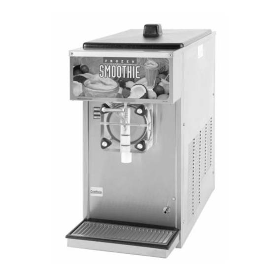
Model 5311
0509 Form# WH-330-09
Part# W0600116
Advertisement
Table of Contents

Related Manuals for Grindmaster 5311


Summary of Contents for Grindmaster 5311
- Page 1 Exploded Views ........24-40 Electrical Diagrams ........41-52 Wiring Diagrams ........53-67 Refrigeration Diagrams......68-69 Prior authorization must be obtained from Model 5311 Grindmaster Corporation for all warranty claims. Grindmaster Corporation 4003 Collins Lane Louisville, KY 40245 USA (502) 425-4776 (800) 695-4500 (USA & Canada only) FAX (502) 425-4664 www.grindmaster.com...
-
Page 3: Installation
If concealed damage and/or shortages are found later, advise the carrier within 10 days and request inspection. The customer must place any claim for damage and/or shortage with the carrier. Figure A Grindmaster Corporation cannot make any claims against the carrier. Crathco 5000 Series Manual Page 3... - Page 4 Removal from Carton and Pallet Remove staples or cut cardboard box around the stapled area. Pull the cardboard box up off machine. Remove the Styrofoam packing and the plastic bag. Remove both side panels with screwdriver. Use a wratchet with a 3 inch extension and a 7/16 socket to remove the shipping bolts (connecting the machine to the pallet) located on both sides of the frame bottom plate.
- Page 5 Installation of Concealed Air Filter Accessory Kit (optional) (Part #s W089.0200 Stainless Steel, W089.0208 Black) Remove the four screws that hold the right side panel on INSTALL THE FILTER PANEL OVER THE the machine. EXISTING SIDE PANEL & RE-INSTALL SCREWS. Install the filter panel over the existing side panel and reinstall screws.
-
Page 6: Operating And Adjustments
Installation of Spinner/Mixer Accessory Kit (optional) (Part #W089.0053-115V) (Part # W0890124-220V) Turn to "off" and unplug the freezer from the Electrical box electrical power source. Remove the white plastic plugs covering the threaded holes on the right front panel (facing the freezer). Remove the electrical box cover. - Page 7 Carburetor Assembly Your new freezer uses a metering device, known as a carburetor, to feed the proper ratio of mix and air into the freezing cylinder. For products such as dairy based shake mixes, the proper mix to air ratio is generally accepted to be two parts mix to one part air.
- Page 8 Computing Overrun (cont.) Draw a heaping cup of frozen product that contains no air pockets. Note: Use a spatula or other device to help fill the cup completely. Avoid tamping the cup as this artificially reduces overrun. Use a straight edge to scrape off excess product flush with the rim of the cup and weigh the cup. Subtract the cup weight and use the overrun formula to determine overrun.
-
Page 9: Product Tips
Mix Low Function (cont.) buzzer is out of the circuit and the light will illuminate fully again. After the 10-minute cycle the mix out safety func- tion is activated making the unit inoperable. The machine is placed into the standby mode to prevent any damage to the machine from running dry of product. - Page 10 Product Consistency Adjustment (cont.) When making adjustments to a thicker (colder) setting, dispense approximately 16 ounces (1/2 liter) of product and recheck consistency after the compressor has cycled off. If the consistency is still not correct, repeat steps 2 and 3. "Standby"...
- Page 11 Consistency Control - Overview (cont.) In the “standby” mode the control board senses the temperature of the product in the barrel. The drive motor is cycled on time only. It will operate for 2 minutes ON then 18 minutes OFF as long as it is in “standby”. The com- pressor and drive motor are cycled independently for the barrel in the “standby”...
-
Page 12: Care And Cleaning
CARE AND CLEANING Note: Each time the freezer is disassembled, all internal freezer components must be thoroughly washed, scoured, and sanitized using procedures recommended by your local health department. In lieu of local health department recommendations, use a three compartment sink; one compartment to wash parts in detergent, one compartment to rinse, and one to sanitize. - Page 13 Daily Cleaning Procedure (cont.) Note: The best way to remove an “O” Ring is to first wipe off all of the lubricant using a clean paper towel. Pinch the “O” Ring upward with a dry towel between your index finger and thumb. When a loop is formed in the “O” Ring, roll it out of the groove with your other thumb.
- Page 14 Sanitizing Carburetor and Valve Components (cont.) Slide the valve plunger spring over the small end of the valve plunger and, using another clean piece of paper toweling, pick up the valve plunger at the outlet end and insert plunger and spring into the valve body (figure Q).
- Page 15 Sanitizing and Refilling (cont.) Watch the product flowing out of the dispensing valve and close the valve when the sanitizer remaining in the cylinder has been purged by the new mix. Use a clean piece of paper toweling to insert the sanitized carburetor assembly into the inlet hole in the hopper (figure V).
- Page 16 Cleaning Following Complete Disassembly of Unit (cont.) IMPORTANT: After disassembly, thoroughly scour each part of the freezer in a warm mild detergent solution including the inside of the freezing cylinder and the mix storage hopper. Rinse each part with clear water. Prepare a minimum of 3-1/2 gallons (13 liters) of sanitizing solution (Divorsol CX or equiva- lent) following the manufacturer's instructions.
- Page 17 Reassembly (cont.) Disassemble the carburetor assembly and remove the O-Rings. Wash and sanitize all parts. Reinstall and lubricate the O-Rings and slip on the outer tube if equipped. (See Figure EE) Figure EE Thick product Standard Low overrun carb tube carb tube carb tube Sanitizing and Refilling...
- Page 18 How to Clean Exposed Filter: Slide exposed filter out of the rails by pulling forward on the filter. It is recommended to remove the filter by using the palm of your hand and applying even pressure to the face of the filter. Clean filter with liquid soap and water.
- Page 19 Annual Maintenance (cont.) Remove dasher assembly, inspect stator bearings and replace shaft seal set. (See Care and Cleaning). Remove rear panel and inspect "V" belt. Inspect the drive shaft square hole for wear (rounding-out). Check drive shaft and motor shaft bearings for excessive wear. Reinstall side and back panels.
- Page 20 5000 SERIES FREEZER SPECIFICATIONS: Specification Model 5311 Model 5511 Model 5711 Model 5941 Circuit NEMA# NEMA 5-20R NEMA 6-20R NEMA 6-20R NEMA 5-15R 208/230 volt, 60 Hz, 1 115 volt, 60 Hz, 1 Phase 208/230 volt, 60 Hz, 115 volt, 60 Hz, 1 Phase Electrical Phase Dedicated 20 Amp circuit...
- Page 21 Quantities Part Every Every Monthly Annually to be Description 3 Months 6 Months Replaced Shaft seal Inspect & replace if necessary Drive shaft Inspect & replace if necessary Drive belts Inspect & replace if necessary Scraper blades Inspect & on dasher replace if necessary Square cut...
-
Page 22: Troubleshooting
TROUBLESHOOTING Problem Possible Cause Solution Freezer will not run or freeze down • Freezer not plugged in • Plug in machine • Circuit breaker tripped or fuse • Reset breaker or replace fuse blown • Freezer in "CLEAN" position • Switch to "FREEZE" •... - Page 23 Friday, 8 am - 6 pm EST) or an authorized service center in your area. Please have the model and serial numbers ready so that accurate information may be given. Prior authorization must be obtained from Grindmaster Corporation’s Technical Services Department for all warranty claims.
-
Page 24: Exploded Views
Exploded View Model 5311 Optional Dasher Part #0430026 Item Part Number Description W0110002 Valve Stud W0210171 Frame Assembly W0520063 Stainless Steel Rear Panel W0520064 Stainless Steel Side Panel Left W0520065 Stainless Steel Side panel Right W0340022 213 O-Ring W0340058 Barrel Gasket W0340210 Seal Set Standard W0389001... - Page 25 Exploded View Model 5511 Item Part Number Description W0110002 Valve Stud W0210171 Frame Assembly W0520063 Stainless Steel Rear Panel W0520064 Stainless Steel Side Panel Left W0520065 Stainless Steel Side Panel Right W0340058 Barrel Gasket W0340210 Shaft Seal Set W0380025 Flange Bearing W0430024 Blind Flange Bearing W0430028...
- Page 26 Exploded View Model 5941 5941 EXPLODED VIEW ITEM QTY. PART NUMBER DESCRIPTION W0210257 BASE ASSEMBLY W0211232 FRAME ASSEMBLY W0201346 EVAPAORATOR ASSY, 5311 & 5511 W0110013 STUD, VALVE NEW STYLE W0450053 PULLEY, 10" W/ 1" BORE W0450209 V-BELT 3L460 X 3/8" FHP Hopper Cover Single W0520094 W0340201...
- Page 27 Exploded View Model 5711 Crathco 5000 Series Manual Page 27 ®...
- Page 28 Exploded View Model 5711 (Spinners) Page 28 Crathco 5000 Series Manual ®...
- Page 29 Exploded View Model 5711 Stock Assembly Crathco 5000 Series Manual Page 29 ®...
- Page 30 Exploded View Model 5711 Stock Assembly (Spinners) Page 30 Crathco 5000 Series Manual ®...
- Page 31 Exploded View Model 5311 Base Assembly Item Part Number Description Item Part Number Description W0450016 Pulley W0210169 Motor Cradle W0610110 #8 X 3/8 Pan Hd.. 0W200123 Compressor W0610264 10-24 X 1/4 Truss Hd. W0200256 Condenser W0321025 Motor Stop Bracket W0200411 Fan Mount Bracket W0611055 10-24 Hex Nut...
- Page 32 Exploded View Model 5511 Base Assembly Item Part Number Description W0210169 Motor Cradle W0200133 Compressor W0200256 Condenser W0200411 Fan Mount Bracket W0200412 Compressor Spacer W0200413 Compressor Grommet W0201079 Fan Shroud W0210041 Frame Bottom Plate W0320020 Drive Motor W0320220 Fan Motor W0320286 Fan Blade W0321013...
- Page 33 Exploded View Model 5941 Base Assembly ITEM QTY. PART NUMBER DESCRIPTION W0210044 BASE PAN ASSEMBLY W0210169 CRADLE, MOTOR 3312/5311 W0320019 MOTOR, DRIVE DUAL CYCLE 1/2 HP Motor Stop Brkt Assy W0321025 W0321013 NUT, MOTOR ADJUSTMENT W0380009 BEARING, 1" BORE FLANGE W0450016 PULLEY, 0K7 X 1/2"...
- Page 34 Exploded View Model 5711 Base Assembly Page 34 Crathco 5000 Series Manual ®...
- Page 35 5311 Base Assembly Refrigeration Item Part Number Description W0650501 Access Valve W0200314 Capillary Tube, .042 x 12 Ft. W0650112 Filter Drier W0200123 Compressor W0200256 Condenser W0650104 Automatic Expansion Valve W0201120 Hopper Coolant Lines W0201331 Suction Line W0620109 3/8" x 3/8" x 1/4" Tee W0201114 Evaporator Line W0201113...
- Page 36 5511 Base Assembly Refrigeration Item Part Number Description W0650501 Access Valve W0200301 Capillary Tube W0650112 Filter Drier W0200133 Compressor W0200256 Condenser W0650107 Automatic Expansion Valve W0201120 Hopper Coolant Lines W0201114 Evaporator Line W0201113 Suction Line W0201323 Exp. Valve/Solenoid Liquid Line W0620102 1/4"...
- Page 37 5941 Base Assembly Refrigeration ITEM QTY. PART NUMBER DESCRIPTION 100280 BRACKET, MOUNTING, QD 5931 W0620118 Quick Disconnect, Male Portion male W0620117 Quick Disconnect, Male Portion male W0650125 VALVE, THERM EXP, 3/8 X 1/2 ODF, 30" CAP W0200312 DRIER, FILTER SPORLAN #C-033-S Tube, Capillary .072 OD x .026 ID x 132"...
- Page 38 Model 5711 Refrigeration Tube Assembly Page 38 Crathco 5000 Series Manual ®...
- Page 39 Exploded View Probe Assembly S.S PROBE - W0572362 ACETAL DELRIN SLEEVE - W0572361 ADD SILICON SEALANT TO BACK OF SLEEVE ONLY MACHINE SCREW - W0610299 INTERNAL TOOTH LOCKWASHER - W0611224 RING EYE TERMINAL FLAT WASHER - W0611241 PLASTIC SPACER - W0572360 HOLE IN REAR OF HOPPER PAN Crathco 5000 Series Manual...
- Page 40 Page 40 Crathco 5000 Series Manual ®...
- Page 41 5311 Electrical Components Item Part Number Description W1650004 HOPPER SOLENOID LBS & RBS W1650004 BARREL SOLENOID WI570616 FUSE HOLDER W0320209 FAN MOTOR W0320019 DRIVE MOTOR W0570712 POWER CORD W0570935 SERVE SWITCH W0570655 DRIVE MOTOR CONTACTOR W0570655 COMPRESSOR CONTACTOR W0570659 TRANSFORMER W0570939 MODE SWITCH W0570603...
- Page 42 5511 Electrical Components 5511-0102-057-3-20-00 Page 42 Crathco 5000 Series Manual ®...
- Page 43 5711 Electrical Components Crathco 5000 Series Manual Page 43 ®...
- Page 44 5311 Front Electrical Box (CR) Page 44 Crathco 5000 Series Manual ®...
- Page 45 5511 Front Electrical Box 5511-0101-057-3-20-00 Crathco 5000 Series Manual Page 45 ®...
- Page 46 5711 Front Electrical Box Page 46 Crathco 5000 Series Manual ®...
- Page 47 5711 Front Electrical Box (Spinners) Crathco 5000 Series Manual Page 47 ®...
-
Page 48: Electrical Box
5311 Electrical Box Item Part Number Description Item Part Number Description W0570603 Start Capacitor W0570043 Light Bulb W0570617 Run Capacitor W0570044 Light Socket W0570655 Contactor W0630006 Bushings 5311-0214-057-11-16-00 W0570916 Reed Switch W0630811 Capacitor Clips W0570638 Compressor Relay W0631629 Electrical Box Lens W0570934 On/Off Switch W1570616... - Page 49 5941 Electrical Box 5941 ELECTRICAL BOX ITEM QTY. PART NUMBER DESCRIPTION Lighted Elec. Box 5311 W0572451 W0570655. Contactor, 24V Coil W0570043 BULB,FLUORESENT W0570044 SOCKET,LIGHT-LEVITON Control Board Mount Assembly W0572706 W0570934 Rocker Switch, DPDT 83231. Rocker Switch, 3 Position w0650913 Control Board Terminal Strip, 8 Position W0570214 Decal, 3.2 Amp Fuse...
- Page 50 Exploded 5711 Electrical Box Page 50 Crathco 5000 Series Manual ®...
- Page 51 Exploded 5711 Electrical Box (Spinners) Crathco 5000 Series Manual Page 51 ®...
- Page 52 5711 Side Electrical Box Page 52 Crathco 5000 Series Manual ®...
-
Page 53: Wiring Diagrams
5311 Spinner Hook-Up with Timer Wiring Diagram Crathco 5000 Series Manual Page 53 ®... - Page 54 5511 Spinner without Timer Hook-Up Wiring Diagram 5511-0100-057-9-14-00 Page 54 Crathco 5000 Series Manual ®...
- Page 55 5711 Spinner with Timer Hook-Up Wiring Diagram Crathco 5000 Series Manual Page 55 ®...
- Page 56 5311 Compressor Wiring Diagram 5511 Compressor Wiring Diagram 5511-0106-057-3-20-00 Page 56 Crathco 5000 Series Manual ®...
- Page 57 5711 Compressor Wiring Diagram Crathco 5000 Series Manual Page 57 ®...
- Page 58 5311 Ladder Diagram 115V 60 Hz Page 58 Crathco 5000 Series Manual ®...
- Page 59 5511 Ladder Diagram 208/230V/50 Hz 5511-0103-057-3-20-00 Crathco 5000 Series Manual Page 59 ®...
- Page 60 5941 Ladder Diagram 115V 60 Hz 115V CURRENT SENSOR ON CB1 R1(1) ON/OFF SWITCH BALLAST FLORECENT LAMP TRANSFORMER 24V AC 24V AC FU2 (3.2 AMP) 12V AC FU1 (5.0 AMP) BARREL THERMISTOR HOPPER THERMISTOR SERVE SWITCH MIX LOW PROBE CURRENT SENSOR ON/STANDBY/CLEAN SWITCH VOLTAGE SENSOR...
- Page 61 5711 Ladder Diagram Crathco 5000 Series Manual Page 61 ®...
- Page 62 5711 Ladder Diagram (Spinners) Page 62 Crathco 5000 Series Manual ®...
-
Page 63: Wiring Diagram
5311 Wiring Diagram Item Part Number Description W0570603 Start Capacitor W0570617 Run Capacitor W0570655 Contactor W0570423 8 Pin Terminal Strip W0570043 Bulb W0570638 Compressor Relay W1650004 Solenoid Coil W0650913 Circuit Board W0570044 Light Socket W0570823 3.2 Amp Fuse W1570616 Fuse Holder W0570659 Transformer W0570045... - Page 64 5511 Wiring Diagram Item Part Number Description W0570619 Start Capacitor W0570617 Run Capacitor W0570655 Contactor W0570213 8 Pin Terminal Strip W0570618 Compressor Relay W0650102 Solenoid Complete W0570823 3.2 Amp Fuse W1570616 Fuse Holder W0570659 Transformer W0570912 On/Off Switch (Toggle) W1570901 Mode Switch W1572132 6 Wire Cable Sub-As...
- Page 65 5941 Wiring Diagram LEFT RIGHT BARREL SOLENOID SPINNER SPINNER HOPPER SOLENOID YELLOW/WHT YELLOW VIOLET/WHT OLET BLACK BLUE BLUE BLK/WHT GREEN TERMINAL BLOCK BLACK BLUE BLUE BLUE BLUE BLUE BLUE BLACK BLUE BLACK WIRING DETAIL BLUE BLUE BLUE BLACK BLK/WHT BLK/WHT YELLOW/WHT VIOLET RIGHT...
- Page 66 5711 Wiring Diagram Page 66 Crathco 5000 Series Manual ®...
- Page 67 5711 Wiring Diagram (Spinners) Crathco 5000 Series Manual Page 67 ®...
-
Page 68: Refrigeration Circuit
Refrigeration Circuit Page 68 Crathco 5000 Series Manual ®... - Page 69 5941 Refrigeration Circuit Crathco 5000 Series Manual Page 69 ®...
- Page 72 Grindmaster® Coffee Grinders and Brewers • PrecisionBrew™ Brewing Systems • Espressimo® Espresso Machines Crathco® Hot Beverage Dispensers • Crathco® Cold and Frozen Beverage Dispensers • AMW Coffee and Tea Systems Tel (502) 425-4776 • Fax (502) 425-4664 • 1-800-695-4500 (USA & Canada only) P.O.
Need help?
Do you have a question about the 5311 and is the answer not in the manual?
Questions and answers