
Related Manuals for Gigabyte GA-E350N-USB3


Summary of Contents for Gigabyte GA-E350N-USB3
- Page 1 GA-E350N-USB3 FT1 BGA motherboard Built in with an AMD E-350 Dual-Core processor User's Manual Rev. 1001 12ME-E350NB3-1001R...
-
Page 3: Identifying Motherboard Revision
GIGABYTE's prior written permission. Documentation Classifications In order to assist in the use of this product, GIGABYTE provides the following types of documentations: For quick set-up of the product, read the Quick Installation Guide included with the product. -
Page 4: Table Of Contents
Table of Contents Box Contents ........................6 Optional Items .........................6 GA-E350N-USB3 Motherboard Layout ................7 GA-E350N-USB3 Motherboard Block Diagram ..............8 Chapter 1 Hardware Installation ..................9 Installation Precautions ................... 9 1-2 Product Specifications ................... 10 Installing the Memory ..................13 Installing an Expansion Card ................. 14 Back Panel Connectors ................. - Page 5 Chapter 3 Drivers Installation ..................49 Installing Chipset Drivers ................49 Application Software ..................50 Technical Manuals ..................50 Contact......................51 System ......................51 Download Center ................... 52 New Utilities ....................52 Chapter 4 Unique Features...................53 Xpress Recovery2 ..................53 BIOS Update Utilities ..................56 4-2-1 Updating the BIOS with the Q-Flash Utility ............
-
Page 6: Box Contents
Box Contents GA-E350N-USB3 motherboard Motherboard driver disk User's Manual Quick Installation Guide Two SATA cables I/O Shield • The box contents above are for reference only and the actual items shall depend on the product package you obtain. The box contents are subject to change without notice. -
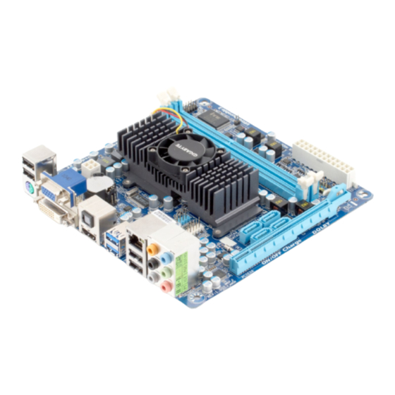
Page 7: Ga-E350N-Usb3 Motherboard Layout
GA-E350N-USB3 Motherboard Layout CPU_FAN KB_MS_USB (Note) DB_PORT ATX_12V AMD E-350 APU CLR_CMOS HDMI_SPDIF Renesas D720200 F_USB2 R_USB30 Realtek Hudson-M1 RTL8111E F_USB1 USB_LAN SPDIF_O SATA3_0 SATA3_3 F_AUDIO AUDIO SATA3_1 SATA3_2 F_PANEL PCIEX4 CODEC (Note) This port is mainly used by repair technicians for debugging and problem diagnosis. -
Page 8: Ga-E350N-Usb3 Motherboard Block Diagram
GA-E350N-USB3 Motherboard Block Diagram CPU CLK+/- (100 MHz) PCI Express Bus D-Sub DDR3 1333 (O.C.)/1066 MHz E-350 APU DDR3 DVI-D PCIe CLK (100 MHz) HDMI 1 PCI Express x4 2 USB 3.0/2.0 RJ45 PCIe CLK 4 SATA 6Gb/s (100 MHz) -
Page 9: Chapter 1 Hardware Installation
Chapter 1 Hardware Installation Installation Precautions The motherboard contains numerous delicate electronic circuits and components which can become damaged as a result of electrostatic discharge (ESD). Prior to installation, carefully read the user's manual and follow these procedures: Prior to installation, do not remove or break motherboard S/N (Serial Number) sticker or •... -
Page 10: Product Specifications
4 GB. Single channel memory architecture Š Support for DDR3 1333 (O.C.)/1066 MHz memory modules Š (Go to GIGABYTE's website for the latest supported memory speeds and memory modules.) Onboard Integrated in the APU: Š... - Page 11 Internal 1 x 24-pin ATX main power connector Š Connectors 1 x 4-pin ATX 12V power connector Š 4 x SATA 6Gb/s connectors Š 1 x CPU fan header Š 1 x system fan header Š 1 x front panel header Š...
- Page 12 Unique Features Support for @BIOS Š Support for Q-Flash Š Support for Xpress BIOS Rescue Š Support for Download Center Š Support for Xpress Install Š Support for Xpress Recovery2 Š Support for EasyTune Š * Available functions in EasyTune may differ by motherboard model. Support for Smart Recovery Š...
-
Page 13: Installing The Memory
Make sure that the motherboard supports the memory. It is recommended that memory of the • same capacity, brand, speed, and chips be used. (Go to GIGABYTE's website for the latest supported memory speeds and memory modules.) Always turn off the computer and unplug the power cord from the power outlet before installing •... -
Page 14: Installing An Expansion Card
Installing an Expansion Card Read the following guidelines before you begin to install an expansion card: • Make sure the motherboard supports the expansion card. Carefully read the manual that came with your expansion card. • Always turn off the computer and unplug the power cord from the power outlet before installing an expansion card to prevent hardware damage. -
Page 15: Back Panel Connectors
Back Panel Connectors USB 2.0/1.1 Port The USB port supports the USB 2.0/1.1 specification. Use this port for USB devices such as a USB key- board/mouse, USB printer, USB flash drive and etc. PS/2 Keyboard/Mouse Port Use this port to connect a PS/2 mouse or keyboard. D-Sub Port The D-Sub port supports a 15-pin D-Sub connector. Connect a monitor that supports D-Sub connection to this port. DVI-D Port (Note) The DVI-D port conforms to the DVI-D specification and supports a maximum resolution of 1920x1200... - Page 16 A. Dual Display Configurations: This motherboard provides three ports for video output: DVI-D, HDMI and D-Sub. The table below shows the supported dual display configurations. Dual Combination Supported or Not DVI-D + D-Sub Display DVI-D + HDMI HDMI + D-Sub B. Playback of HD DVD and Blu-ray Discs: In order to get better playback quality, when playing the HD DVD or Blu-ray discs, refer to the recom- mended system requirements (or better) below.
- Page 17 Step 4: When prompted to confirm, click OK. The custom resolution you defined will appear on the list. To keep the resolution on the list, click Apply. Step 5: From the list, select the custom resolution and click Apply Format to complete. USB 3.0/2.0 Port The USB 3.0 port supports the USB 3.0 specification and is compatible to the USB 2.0/1.1 specification. Use this port for USB devices such as a USB keyboard/mouse, USB printer, USB flash drive and etc. RJ-45 LAN Port The Gigabit Ethernet LAN port provides Internet connection at up to 1 Gbps data rate.
- Page 18 Center/Subwoofer Speaker Out Jack (Orange) Use this audio jack to connect center/subwoofer speakers in a 5.1/7.1-channel audio configuration. Rear Speaker Out Jack (Black) Use this audio jack to connect rear speakers in a 7.1-channel audio configuration. Side Speaker Out Jack (Gray) Use this audio jack to connect side speakers in a 4/5.1/7.1-channel audio configuration. Line In Jack (Blue) The default line in jack. Use this audio jack for line in devices such as an optical drive, walkman, etc. Line Out Jack (Green) The default line out jack.
-
Page 19: Internal Connectors
Internal Connectors ATX_12V F_PANEL F_AUDIO CPU_FAN SPDIF_O SYS_FAN F_USB1/F_USB2 SATA3_0/1/2/3 PWR_LED CLR_CMOS Read the following guidelines before connecting external devices: First make sure your devices are compliant with the connectors you wish to connect. • Before installing the devices, be sure to turn off the devices and your computer. Unplug the •... - Page 20 1/2) ATX_12V/ATX (2x2 12V Power Connector and 2x12 Main Power Connector) With the use of the power connector, the power supply can supply enough stable power to all the com- ponents on the motherboard. Before connecting the power connector, first make sure the power supply is turned off and all devices are properly installed. The power connector possesses a foolproof design. Connect the power supply cable to the power connector in the correct orientation.
- Page 21 3/4) CPU_FAN/SYS_FAN (Fan Headers) The motherboard has a 3-pin CPU fan header (CPU_FAN), a 3-pin system fan header (SYS_FAN). Most fan headers possess a foolproof insertion design. When connecting a fan cable, be sure to connect it in the correct orientation (the black connector wire is the ground wire). For optimum heat dissipation, it is recommended that a system fan be installed inside the chassis.
- Page 22 6) PWR_LED (System Power LED Header) This header can be used to connect a system power LED on the chassis to indicate system power sta- tus. The LED is on when the system is operating. The LED is off when the system is in S3/S4 sleep state or powered off (S5).
- Page 23 8) F_PANEL (Front Panel Header) Connect the power switch, reset switch, and system status indicator on the chassis to this header ac- cording to the pin assignments below. Note the positive and negative pins before connecting the cables. RES+ Power Switch Reset Switch RES- MSG-...
- Page 24 9) F_AUDIO (Front Panel Audio Header) The front panel audio header supports Intel High Definition audio (HD) and AC'97 audio. You may connect your chassis front panel audio module to this header. Make sure the wire assignments of the module con- nector match the pin assignments of the motherboard header. Incorrect connection between the module connector and the motherboard header will make the device unable to work or even damage it. For HD Front Panel Audio: For AC'97 Front Panel Audio: Pin No.
- Page 25 11) F_USB1/F_USB2 (USB 2.0/1.1 Headers) The headers conform to USB 2.0/1.1 specification. Each USB header can provide two USB ports via an optional USB bracket. For purchasing the optional USB bracket, please contact the local dealer. Pin No. Definition Power (5V) Power (5V) USB DX- USB DY- USB DX+ USB DY+ No Pin When the system is in S4/S5 mode, only the USB ports routed to the F_USB1 header can sup- port the ON/OFF Charge function.
- Page 26 13) CLR_CMOS (Clearing CMOS Jumper) Use this jumper to clear the CMOS values (e.g. date information and BIOS configurations) and reset the CMOS values to factory defaults. To clear the CMOS values, place a jumper cap on the two pins to temporarily short the two pins or use a metal object like a screwdriver to touch the two pins for a few seconds.
-
Page 27: Chapter 2 Bios Setup
To see more advanced BIOS Setup menu options, you can press <Ctrl> + <F1> in the main menu of the BIOS Setup program. To upgrade the BIOS, use either the GIGABYTE Q-Flash or @BIOS utility. Q-Flash allows the user to quickly and easily upgrade or back up BIOS without entering the operating •... -
Page 28: Startup Screen
Startup Screen The following screens may appear when the computer boots. Award Modular BIOS v6.00PG Copyright (C) 1984-2010, Award Software, Inc. GA-E350N-USB3 D20 Motherboard Model BIOS Version Function Keys <DEL>: BIOS Setup <F9>: XpressRecovery2 <F12>: Boot Menu <End>: Qflash 12/29/2010-Zacate-Hudson-7A66EG01C-00 Function Keys: <DEL>: BIOS SETUP\Q-FLASH... -
Page 29: The Main Menu
The Main Menu Once you enter the BIOS Setup program, the Main Menu (as shown below) appears on the screen. Use ar- row keys to move among the items and press <Enter> to accept or enter a sub-menu. (Sample BIOS Version: D20) CMOS Setup Utility-Copyright (C) 1984-2010 Award Software MB Intelligent Tweaker(M.I.T.) Load Fail-Safe Defaults... - Page 30 The Functions of the <F11> and <F12> keys (For the Main Menu Only) F11: Save CMOS to BIOS This function allows you to save the current BIOS settings to a profile. You can create up to 8 profiles (Profile 1-8) and name each profile. First enter the profile name (to erase the default profile name, use the SPACE key) and then press <Enter> to complete. F12: Load CMOS from BIOS If your system becomes unstable and you have loaded the BIOS default settings, you can use this function to load the BIOS settings from a profile created before, without the hassles of reconfiguring the BIOS settings. First select the profile you wish to load, then press <Enter> to complete.
-
Page 31: Mb Intelligent Tweaker(M.i.t.)
MB Intelligent Tweaker(M.I.T.) CMOS Setup Utility-Copyright (C) 1984-2010 Award Software MB Intelligent Tweaker(M.I.T.) Item Help IGX Configuration [Press Enter] Menu Level CPU Frequency(MHz) [Normal] CPU Host Clock Control [Auto] x CPU Host Clock PCIe Spread Spectrum [Disabled] Set Memory Clock [Auto] x Memory Clock x5.33 1066Mhz DRAM Configuration [Press Enter] ******** System Voltage Optimized ******** System Voltage Control... - Page 32 VGA Core Clock control Allows you to determine whether to manually set the VGA Core clock. (Default: Auto) VGA Core Clock(MHz) Allows you to manually set the VGA Core clock. The adjustable range is from 300 MHz to 2000 MHz. This item is configurable only when the VGA Core Clock control option is set to Manual.
- Page 33 DRAM Configuration CMOS Setup Utility-Copyright (C) 1984-2010 Award Software DRAM Configuration Item Help DDR3 Timing Items [Auto] SPD Auto Menu Level x 1T/2T Command Timing Auto x CAS# latency Auto x RAS to CAS R/W Delay Auto x Row Precharge Time Auto x Minimum RAS Active Time Auto x TwTr Command Delay Auto...
- Page 34 RAS to RAS Delay Options are: Auto (default), 4T~8T. Four Bank Activate Window Options are: Auto (default), 16T~32T. Bank Interleaving Enables or disables memory bank interleaving. Enabled allows the system to simultaneously access dif- ferent banks of the memory to increase memory performance and stability. (Default: Enabled) ******** System Voltage Optimized ******** System Voltage Control Determines whether to manually set the system voltages.
-
Page 35: Standard Cmos Features
Standard CMOS Features CMOS Setup Utility-Copyright (C) 1984-2010 Award Software Standard CMOS Features Item Help Date (mm:dd:yy) Wed, Dec 29 2010 Menu Level Time (hh:mm:ss) 22:31:24 IDE Channel 0 Master [None] IDE Channel 0 Slave [None] IDE Channel 1 Master [None] IDE Channel 1 Slave [None] Halt On [All, But Keyboard] Base Memory 640K... - Page 36 Halt On Allows you to determine whether the system will stop for an error during the POST. All Errors Whenever the BIOS detects a non-fatal error the system boot will stop. No Errors The system boot will not stop for any error. All, But Keyboard The system boot will not stop for a keyboard error but stop for all other errors.
-
Page 37: Advanced Bios Features
Advanced BIOS Features CMOS Setup Utility-Copyright (C) 1984-2010 Award Software Advanced BIOS Features Item Help IGX Configuration [Press Enter] Menu Level AMD K8 Cool&Quiet control [Auto] Hard Disk Boot Priority [Press Enter] First Boot Device [Hard Disk] Second Boot Device [CDROM] Third Boot Device [USB-HDD] Password Check [Setup] HDD S.M.A.R.T. Capability [Disabled] Away Mode [Disabled] Backup BIOS Image to HDD [Disabled] Init Display First [PEG] higf: Move Enter: Select... - Page 38 Away Mode Enables or disables Away Mode in Windows XP Media Center operating system. Away Mode allows the system to silently perform unattended tasks while in a low-power mode that appears off. (Default: Disabled) Backup BIOS Image to HDD Allows the system to copy the BIOS image file to the hard drive. If the system BIOS is corrupted, it will be recovered from this image file. (Default: Disabled) Init Display First Specifies the first initiation of the monitor display from the PCI Express graphics card or the onboard...
-
Page 39: Integrated Peripherals
Integrated Peripherals CMOS Setup Utility-Copyright (C) 1984-2010 Award Software Integrated Peripherals Item Help OnChip SATA Controller [Enabled] Menu Level OnChip SATA Type [Native IDE] OnChip SATA3.0 Support [Enabled] x OnChip SATA Port as ESP Press Enter Onboard LAN Function [Enabled] Onboard LAN Boot ROM [Disabled] SMART LAN [Press Enter] Onboard Audio Function [Enabled] Onboard USB 3.0 Controller [Enabled] USB Controllers [Enabled] USB Legacy Function... - Page 40 Onboard LAN Function Enables or disables the onboard LAN function. (Default: Enabled) If you wish to install a 3rd party add-in network card instead of using the onboard LAN, set this item to Disabled. Onboard LAN Boot ROM Allows you to decide whether to activate the boot ROM integrated with the onboard LAN chip. (Default: Disabled) SMART LAN (LAN Cable Diagnostic Function) CMOS Setup Utility-Copyright (C) 1984-2010 Award Software...
- Page 41 Onboard Audio Function Enables or disables the onboard audio function. (Default: Enabled) If you wish to install a 3rd party add-in audio card instead of using the onboard audio, set this item to Disabled. Onboard USB 3.0 Controller (Renesas D720200 USB Controller) Enables or disables the Renesas D720200 USB controller.
-
Page 42: Power Management Setup
Power Management Setup CMOS Setup Utility-Copyright (C) 1984-2010 Award Software Power Management Setup Item Help ACPI Suspend Type [S3(STR)] Menu Level Soft-Off by Power button [Instant-off] USB Wake Up from S3 [Enabled] Modem Ring Resume [Disabled] PME Event Wake Up [Enabled] HPET Support [Enabled] (Note) Power On By Mouse [Disabled] Power On By Keyboard [Disabled] x KB Power ON Password Enter AC Back Function [Soft-Off] Power-On by Alarm [Disabled] x Date (of Month) - Page 43 Power On By Mouse Allows the system to be turned on by a PS/2 mouse wake-up event. Note: To use this function, you need an ATX power supply providing at least 1A on the +5VSB lead. Disabled Disables this function. (Default) Double Click Double click on left button on the PS/2 mouse to turn on the system.
-
Page 44: Pc Health Status
PC Health Status CMOS Setup Utility-Copyright (C) 1984-2010 Award Software PC Health Status Item Help Reset Case Open Status [Disabled] Menu Level Case Opened Vcore 1.392V DDR3 1.5V 1.488V +3.3V 3.248V +12V 12.239V Current System Temperature Current CPU Temperature Current CPU FAN Speed 5400 RPM Current SYSTEM FAN Speed 0 RPM... -
Page 45: Load Fail-Safe Defaults
Load Fail-Safe Defaults CMOS Setup Utility-Copyright (C) 1984-2010 Award Software MB Intelligent Tweaker(M.I.T.) Load Fail-Safe Defaults Standard CMOS Features Load Optimized Defaults Advanced BIOS Features Set Supervisor Password Integrated Peripherals Set User Password Power Management Setup Save &... -
Page 46: Set Supervisor/User Password
2-11 Set Supervisor/User Password CMOS Setup Utility-Copyright (C) 1984-2010 Award Software MB Intelligent Tweaker(M.I.T.) Load Fail-Safe Defaults Standard CMOS Features Load Optimized Defaults Advanced BIOS Features Set Supervisor Password Integrated Peripherals Set User Password Power Management Setup Save &... -
Page 47: Save & Exit Setup
2-12 Save & Exit Setup CMOS Setup Utility-Copyright (C) 1984-2010 Award Software MB Intelligent Tweaker(M.I.T.) Load Fail-Safe Defaults Standard CMOS Features Load Optimized Defaults Save to CMOS and EXIT (Y/N)? Y Advanced BIOS Features Set Supervisor Password Integrated Peripherals Set User Password ... - Page 48 BIOS Setup - 48 -...
-
Page 49: Chapter 3 Drivers Installation
• After "Xpress Install" installs all of the drivers, a dialog box will appear asking whether to install new GIGABYTE utilities. Click Yes to automatically install the utilities. Or click No if you want to manually select the utilities to install on the Application Software page later. -
Page 50: Application Software
Application Software This page displays all the utilities and applications that GIGABYTE develops and some free software. You can click the Install button on the right of an item to install it. Technical Manuals This page provides GIGABYTE's application guides, content descriptions for this driver disk, and the mother- board manuals. -
Page 51: Contact
Contact For the detailed contact information of the GIGABYTE Taiwan headquarter or worldwide branch offices, click the URL on this page to link to the GIGABYTE website. System This page provides the basic system information. - 51 - Drivers Installation... -
Page 52: Download Center
The latest version of the BIOS, drivers, or applications will be displayed. New Utilities This page provides a quick link to GIGABYTE's lately developed utilities for users to install. You can click the Install button on the right of an item to install it. -
Page 53: Chapter 4 Unique Features
Chapter 4 Unique Features Xpress Recovery2 Xpress Recovery2 is a utility that allows you to quickly compress and back up your system data and perform restoration of it. Supporting NTFS, FAT32, and FAT16 file systems, Xpress Recovery2 can back up data on PATA and SATA hard drives and restore it. - Page 54 Step 3: Step 4: When partitioning your hard drive, make sure to After the operating system is installed, click Start, leave unallocated space (10 GB or more is recom- right-click the Computer and select Manage. Go to mended; actual size requirements vary, depending Disk Management to check disk allocation.
- Page 55 D. Using the Restore Function in Xpress Recovery2 Select RESTORE to restore the backup to your hard drive in case the system breaks down. The RESTORE option will not be present if no backup is created before. E. Removing the Backup Step 1: Step 2: If you wish to remove the backup file, select...
-
Page 56: Bios Update Utilities
BIOS Update Utilities GIGABYTE motherboards provide two unique BIOS update tools, Q-Flash and @BIOS . GIGABYTE ™ ™ Q-Flash and @BIOS are easy-to-use and allow you to update the BIOS without the need to enter MS-DOS mode. Additionally, this motherboard features the DualBIOS design, which enhances protection for the ™... - Page 57 B. Updating the BIOS When updating the BIOS, choose the location where the BIOS file is saved. The following procedure as- sumes that you save the BIOS file to a USB flash drive. Step 1: 1. Insert the USB flash drive containing the BIOS file into the computer. In the main menu of Q-Flash, use the up or down arrow key to select Update BIOS from Drive and press <Enter>. •...
- Page 58 Step 4: Press <Esc> and then <Enter> to exit Q-Flash and reboot the system. As the system boots, you should see the new BIOS version is present on the POST screen. Step 5: During the POST, press <Delete> to enter BIOS Setup. Select Load Optimized Defaults and press <Enter> to load BIOS defaults.
-
Page 59: Updating The Bios With The @Bios Utility
BIOS or a system that is unable to start. Do not use the G.O.M. (GIGABYTE Online Management) function when using @BIOS. GIGABYTE product warranty does not cover any BIOS damage or system failure resulting from an inad- equate BIOS flashing. -
Page 60: Easytune 6
EasyTune 6 GIGABYTE's EasyTune 6 is a simple and easy-to-use interface that allows users to fine-tune their system settings or do overclock/overvoltage in Windows environment. The user-friendly EasyTune 6 interface also includes tabbed pages for CPU and memory information, letting users read their system-related information without the need to install additional software. The EasyTune 6 Interface... -
Page 61: Q-Share
Q-Share, you are able to share your data with computers on the same network, making full use of Internet resources. Directions for using Q-Share After installing Q-Share from the motherboard driver disk, go to Start>All Programs>GIGABYTE>Q-Share. exe to launch the Q-Share tool. Find the Q-Share icon in the notification area and right-click on this icon to configure the data sharing settings. -
Page 62: Smart Recovery
SMART Recovery With SMART Recovery, users can quickly create backups of changed data files or copy files from a spe- (Note 1) cific backup on PATA and SATA hard drives (partitioned on NTFS file system) in Windows Vista. Instructions: In the main menu, click the Config button to open the Smart Recov- ery Preference dialog box. The Smart Recovery Preference dialog box: Button Function Enable Enables automatic daily backup (Note 2) Schedule Sets a daily backup schedule Capacity... -
Page 63: Auto Green
Auto Green Auto Green is an easy-to-use tool that provides users with simple options to enable system power savings via a Bluetooth cell phone. When the phone is out of the range of the computer's Bluetooth receiver, the sys- tem will enter the specified power saving mode. The Configuration dialog box: First, you have to set your Bluetooth cell phone as a portable key. - Page 64 Unique Features - 64 -...
-
Page 65: Chapter 5 Appendix
Chapter 5 Appendix Configuring Audio Input and Output 5-1-1 Configuring 2/4/5.1/7.1-Channel Audio The motherboard provides six audio jacks on the back panel which support 2/4/5.1/7.1-channel audio. (Note) The picture to the right shows the default audio jack Center/Subwoofer Line In Speaker Out assignments. - Page 66 Step 2: Connect an audio device to an audio jack. The The cur- rent connected device is dialog box appears. Select the device according to the type of device you connect. Then click OK. Step 3: On the Speakers screen, click the Speaker Configura- tion tab.
-
Page 67: Configuring S/Pdif Out
5-1-2 Configuring S/PDIF Out The S/PDIF Out jack can transmit audio signals to an external decoder for decoding to get the best au- (Note 1) dio quality. 1. Connecting a S/PDIF Out Cable: S/PDIF Optical Cable Connect a S/PDIF optical cable to an external decoder for transmitting the S/PDIF digital audio signals. 2. -
Page 68: Enabling The Dolby Home Theater Function
5-1-3 Enabling the Dolby Home Theater Function Before Dolby Home Theater is enabled, you get only 2-channel playback output (from the front speakers) when playing 2-channel stereo sources. You must play 4-, 5.1-, or 7.1- chan- nel content to get 4-, 5.1-, or 7.1- channel audio effects. With Dolby Home Theater enabled, 2-channel stereo content will be transformed into multi-channel audio, creating a virtual sur- round sound environment. -
Page 69: Configuring Microphone Recording
5-1-4 Configuring Microphone Recording Step 1: After installing the audio driver, the HD Audio Manager icon will appear in the notification area. Double-click the icon to access the HD Audio Manager. Step 2: Connect your microphone to the Mic in jack (pink) on the back panel or the Mic in jack (pink) on the front panel. Then configure the jack for microphone function- ality. - Page 70 Step 5: After completing the settings above, click Start, point to All Programs, point to Accessories, and then click Sound Recorder to begin the sound recording. * Enabling Stereo Mix If the HD Audio Manager does not display the recording device you wish to use, refer to the steps below. The following steps explain how to enable Stereo Mix (which may be needed when you want to record sound from your computer).
-
Page 71: Using The Sound Recorder
Step 4: Now you can access the HD Audio Manager to config- ure Stereo Mix and use Sound Recorder to record the sound. 5-1-5 Using the Sound Recorder A. Recording Sound 1. Make sure you have connected the sound input device (e.g. microphone) to the computer. 2. -
Page 72: Troubleshooting
Troubleshooting 5-2-1 Frequently Asked Questions To read more FAQs for your motherboard, please go to the Support & Downloads\FAQ page on GIGABYTE's website. Q: In the BIOS Setup program, why are some BIOS options missing? A: Some advanced options are hidden in the BIOS Setup program. Press <Delete> to enter BIOS Setup during the POST. In the Main Menu, press <Ctrl>+<F1>... -
Page 73: Troubleshooting Procedure
5-2-2 Troubleshooting Procedure If you encounter any troubles during system startup, follow the troubleshooting procedure below to solve the problem. START Turn off the power. Remove all peripherals, connecting cables, and power cord etc. Make sure the motherboard does not short-circuit with the chassis or Isolate the short circuit. - Page 74 The power supply, CPU or When the computer is turned on, is the CPU cooler running? CPU socket might fail. The problem is verified and solved. The graphics card, expansion slot, or monitor Check if there is display on your monitor. might fail. The problem is verified and solved. Turn off the computer. Plug in the keyboard and mouse and restart the computer.
- Page 75 - 75 - Appendix...
- Page 76 Appendix - 76 -...
- Page 77 - 77 - Appendix...
- Page 78 Appendix - 78 -...
- Page 79 Web address: http://latam.giga-byte.com TEL: +86-24-83992901 • Giga-Byte SINGAPORE PTE. LTD. - Singapore FAX: +86-24-83992909 WEB address : http://www.gigabyte.sg • GIGABYTE TECHNOLOGY (INDIA) LIMITED - India • Thailand WEB address : http://www.gigabyte.in WEB address : http://th.giga-byte.com • Saudi Arabia • Vietnam WEB address : http://www.gigabyte.com.sa...
- Page 80 WEB address : http://www.gigabyte.com.gr WEB address : http://www.gigabyte.kz • Czech Republic You may go to the GIGABYTE website, select your language WEB address : http://www.gigabyte.cz in the language list on the top right corner of the website. • GIGABYTE Global Service System...
Need help?
Do you have a question about the GA-E350N-USB3 and is the answer not in the manual?
Questions and answers