Intel DG41TX Product Manual
Desktop board
Hide thumbs
Also See for DG41TX:
- Technical product specification (90 pages) ,
- Specification (6 pages) ,
- Product manual (80 pages)
Table of Contents
Advertisement
Advertisement
Table of Contents

Related Manuals for Intel DG41TX


Summary of Contents for Intel DG41TX
- Page 1 Intel Desktop Board DG41TX ® Product Guide Order Number: E88309-001...
-
Page 2: Revision History
Intel may make changes to specifications and product descriptions at any time, without notice. Intel Desktop Board DG41TX may contain design defects or errors known as errata which may cause the product to deviate from published specifications. Current characterized errata are available on request. -
Page 3: Intended Audience
The suitability of this product for other PC or embedded non-PC applications or other environments, such as medical, industrial, alarm systems, test equipment, etc. may not be supported without further evaluation by Intel. Document Organization The chapters in this Product Guide are arranged as follows:... - Page 4 Intel Desktop Board DG41TX Product Guide Terminology The table below gives descriptions of some common terms used in the product guide. Term Description Gigabyte (1,073,741,824 bytes) Gigahertz (one billion hertz) Kilobyte (1024 bytes) Kilohertz (one thousand hertz) Megabyte (1,048,576 bytes)
-
Page 5: Table Of Contents
Processor......................14 Main Memory.....................15 ® Intel G41 Express Chipset** ................16 Intel G41 Graphics Subsystem..............16 Intel GMA X4500 Graphics Controller .............16 External PCI Express x16 Graphics............17 Audio Subsystem ....................17 Legacy Input/Output (I/O) Controller ..............18 LAN Subsystem ....................19 Hi-Speed USB 2.0 Support ..................20 ATA Support......................20... - Page 6 ® Updating the BIOS with the Intel Express BIOS Update Utility.........63 ® Updating the BIOS with the ISO Image BIOS Update File or the Intel Flash Memory Update Utility...................64 Obtaining the BIOS Update File ..............64 Updating the BIOS with the ISO Image BIOS Update File .........64 Updating the BIOS with the Intel Flash Memory Update Utility......65...
- Page 7 22. Back Panel Audio Connectors .................51 23. Location of the Chassis Fan Headers..............52 24. Connecting Power Supply Cables ..............53 25. Location of the BIOS Configuration Jumper Block ..........54 26. Removing the Battery ...................61 27. Intel Desktop Board DG41TX China RoHS Material Self Declaration Table....74...
- Page 8 3. Back Panel and Front Panel Audio Jack Retasking Support ........18 4. LAN Connector LEDs ..................19 5. Front Panel Audio Header Signal Names for Intel HD Audio .........48 6. Front Panel Audio Header Signal Names for AC ’97 Audio ........48 7.
-
Page 9: Desktop Board Features
SDRAM interface • Support for up to 4 GB of main memory ® Chipset • Intel G41 Express Chipset** consisting of: • Intel G41 Express Chipset** Graphics and Memory Controller Hub (GMCH) ® • Intel 82801G I/O Controller Hub (ICH7) ®... - Page 10 Intel Desktop Board DG41TX Product Guide Table 1. Feature Summary (continued) Peripheral • Eight USB 2.0 ports: Interfaces ― Four ports routed to the back panel ― Four ports routed to two front panel USB headers • Four Serial ATA (SATA) channels (3.0 Gb/s) via ICH7 •...
-
Page 11: Supported Operating Systems
Desktop Board Features Supported Operating Systems The Desktop Board supports the following operating systems: • Microsoft Windows* 7 Ultimate • Microsoft Windows 7 Home Premium • Microsoft Windows 7 Basic • Microsoft Windows Vista* Ultimate • Microsoft Windows Vista Enterprise •... -
Page 12: Desktop Board Components
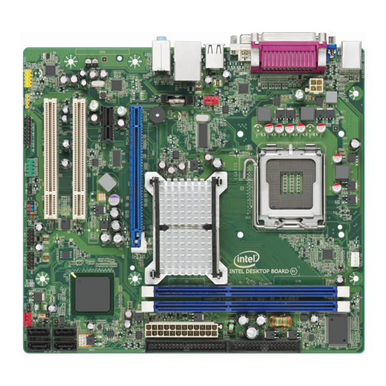
Intel Desktop Board DG41TX Product Guide Desktop Board Components Figure 1 shows the approximate location of the major components on Intel Desktop Board DG41TX. Figure 1. Intel Desktop Board DG41TX Components... - Page 13 Desktop Board Features Table 2. Intel Desktop Board DG41TX Components Label Description Front panel audio header PCI bus connector PCI bus connector PCI Express x1 connector PCI Express x16 connector Speaker Back panel connectors 12 V processor core voltage connector (2 x 2 pin)
-
Page 14: Online Support
Processors are not included with the Desktop Board and must be purchased separately. The processor connects to the Desktop Board through the LGA775 socket. For instructions on installing or upgrading the processor, refer to page 33. A list of supported processors for Intel Desktop Board DG41TX, can be found at http://processormatch.intel.com. -
Page 15: Main Memory
(ii) cause the processor and other system components to fail; (iii) cause reductions in system performance; (iv) cause additional heat or other damage; and (v) affect system data integrity. Intel has not tested, and does not warranty, the operation of the memory beyond its specifications. -
Page 16: Intel G41 Express Chipset
The GMA X4500 graphics controller supports dual independent displays via VGA and DVI-D connectors on the Desktop Board back panel. When a PCI Express Graphics (x16, x8, or x4) add-in card is installed on the Desktop Board, the Intel GMA X4500 graphics controller is disabled. -
Page 17: External Pci Express X16 Graphics
For more information on PCI Express technology, go to http://pcisig.com. Audio Subsystem The onboard audio subsystem consists of the following: • Intel ICH7 I/O controller hub • Realtek ALC888VC 8-channel audio codec • Front panel audio header with support for: ⎯... -
Page 18: Legacy Input/Output (I/O) Controller
Intel Desktop Board DG41TX Product Guide Go to the following locations for more information about: • Audio drivers and utilities http://www.intel.com/support/motherboards/desktop • Location of the onboard audio headers, Figure 21 on page 47 • The location and description of the back panel audio connectors, Figure 22 on page 51 Table 3 lists the supported functions for the front panel and back panel audio jacks. -
Page 19: Lan Subsystem
Desktop Board Features LAN Subsystem The LAN subsystem includes: • Intel ICH7 • Broadcom NetLink BCM5788 Gigabit (10/100/1000 Mb/s) Ethernet LAN controller • RJ-45 LAN connector with integrated status LEDs The subsystem features: • CSMA/CD protocol engine • LAN connect interface between ICH7 and the controller •... -
Page 20: Hi-Speed Usb 2.0 Support
Intel Desktop Board DG41TX Product Guide Hi-Speed USB 2.0 Support The Desktop Board supports up to eight USB 2.0 ports (four ports routed to the back panel and four ports routed to three internal headers) via ICH7. USB 2.0 ports are backward compatible with USB 1.1 devices. -
Page 21: Sata Interfaces
Desktop Board Features SATA Interfaces The ICH7 SATA controller provides four independent SATA ports with a theoretical maximum transfer rate of 3.0 Gb/s on each port. One device can be installed on each port for a maximum of four SATA devices. A point-to-point interface is used for host to device connections, unlike PATA which supports a master/slave configuration and two devices on each channel. -
Page 22: Pci And Pci Express* Auto Configuration
For instructions on resetting the password, see “Clearing Passwords in the BIOS Setup Program” on page 55. Hardware Management Features The hardware management features of Intel Desktop Board DG41TX enable the board to be compatible with the Wired for Management (WfM) specification. The board has several hardware management features including the following: •... -
Page 23: Fan Speed, Thermal, And Voltage Monitoring And Control
Desktop Board Features Fan Speed, Thermal, and Voltage Monitoring and Control Features of the board’s fan speed, thermal, and voltage monitoring and control subsystem include: • Monitoring of power supply voltages to detect levels above and below acceptable values. • Smart fan control provided by the legacy I/O controller, delivering acoustically- optimized thermal management. -
Page 24: Hardware Support
Intel Desktop Board DG41TX Product Guide Hardware Support Power Connectors ATX12V-compliant power supplies can turn off the computer power through system control. When an ACPI-enabled computer receives the correct command, the power supply removes all non-standby voltages. When resuming from an AC power failure, the computer returns to the power state it was in before power was interrupted (either on or off). -
Page 25: Instantly Available Pc Technology
Desktop Board Features Instantly Available PC Technology CAUTIONS For Instantly Available PC technology, the 5 V standby line for the power supply must be capable of delivering adequate +5 V standby current. Failure to provide adequate standby current when using this feature can damage the power supply and/or effect ACPI S3 sleep state functionality. -
Page 26: Wake From Usb
Intel Desktop Board DG41TX Product Guide Figure 3. Location of the +5 V Standby Power Indicator For more information on standby current requirements for the Desktop Board, refer to the Technical Product Specification at http://www.intel.com/support/motherboards/desktop. Wake from USB NOTE Wake from USB requires the use of a USB peripheral that supports Wake from USB. -
Page 27: Wake# Signal Wake-Up Support
Desktop Board Features WAKE# Signal Wake-up Support When the WAKE# signal on the PCI Express bus is asserted, the computer wakes from an ACPI S1, S3, S4, or S5 state. Wake from PS/2 Activity on the PS/2 port wakes the computer from an ACPI S1 or S3 state. Speaker A speaker is mounted on the Desktop Board. - Page 28 Intel Desktop Board DG41TX Product Guide...
-
Page 29: Installing And Replacing Desktop Board Components
2 Installing and Replacing Desktop Board Components This chapter tells you how to: • Install the I/O shield • Install and remove the Desktop Board • Install and remove a processor • Install and remove memory • Install and remove a PCI Express x16 card •... -
Page 30: Installation Precautions
Intel Desktop Board DG41TX Product Guide Installation Precautions When you install and test the Desktop Board, observe all warnings and cautions in the installation instructions. To avoid injury, be careful of: • Sharp pins on connectors • Sharp pins on printed circuit assemblies •... -
Page 31: Installing The I/O Shield
Installing and Replacing Desktop Board Components Installing the I/O Shield The Desktop Board comes with an I/O shield. When installed in the chassis, the shield blocks radio frequency transmissions, protects internal components from dust and foreign objects, and promotes correct airflow within the chassis. Install the I/O shield before installing the Desktop Board in the chassis. -
Page 32: Installing And Removing The Desktop Board
Refer to your chassis manual for instructions on installing and removing the Desktop Board. Figure 5 shows the location of the mounting screw holes for Intel Desktop Board DG41TX. Figure 5. Intel Desktop Board DG41TX Mounting Screw Hole Locations... -
Page 33: Installing And Removing A Processor
Installing and Replacing Desktop Board Components Installing and Removing a Processor This section contains information on how to install and remove a processor on the Desktop Board. Installing a Processor CAUTION Before installing or removing the processor, make sure the AC power has been removed by unplugging the power cord from the computer;... -
Page 34: Lift The Load Plate
Intel Desktop Board DG41TX Product Guide 3. Lift the load plate (Figure 7, A). Do not touch the socket contacts (Figure 7, B). Figure 7. Lift the Load Plate 4. Remove the plastic protective socket cover from the load plate (Figure 8). Do not discard the protective socket cover. -
Page 35: Remove The Processor From The Protective Processor Cover
Installing and Replacing Desktop Board Components 5. Remove the processor from the protective processor cover. Hold the processor only at the edges, being careful not to touch the bottom of the processor (see Figure 9). Do not discard the protective processor cover. Always replace the processor cover if the processor is removed from the socket. -
Page 36: Installing A Processor Fan Heat Sink
Figure 11. Close the Load Plate Installing a Processor Fan Heat Sink Intel Desktop Board DG41TX has mounting holes for a processor fan heat sink. For instructions on how to attach the processor fan heat sink to the Desktop Board, refer to the boxed processor manual. -
Page 37: Removing The Processor
Installing and Replacing Desktop Board Components Figure 12. Connecting the Processor Fan Heat Sink Cable Removing the Processor For instructions on how to remove the processor fan heat sink and processor, refer to the processor installation manual. -
Page 38: Installing And Removing Memory
Intel Desktop Board DG41TX Product Guide Installing and Removing Memory The Desktop Board has two 240-pin DDR3 DIMM sockets providing Channel A and Channel B. For optimum dual-channel performance, install a matched pair of DIMMs equal in speed and size (see Figure 13). -
Page 39: Installing Dimms
Installing and Replacing Desktop Board Components Installing DIMMs To make sure you have the correct DIMM, place it on the illustration of the DDR3 DIMM in Figure 14. All the notches should match with the DDR3 DIMM. Figure 14. Use DDR3 DIMMs... -
Page 40: Installing A Dimm
Intel Desktop Board DG41TX Product Guide To install a DIMM, follow these steps: 1. Observe the precautions in "Before You Begin" on page 29. 2. Turn off all peripheral devices connected to the computer. Turn off the computer and disconnect the AC power cord. -
Page 41: Removing Dimms
Installing and Replacing Desktop Board Components Removing DIMMs To remove a DIMM, follow these steps: 1. Observe the precautions in "Before You Begin" on page 29. 2. Turn off all peripheral devices connected to the computer. Turn off the computer. 3. -
Page 42: Installing And Removing A Pci Express X16 Card
Intel Desktop Board DG41TX Product Guide Installing and Removing a PCI Express x16 Card CAUTION When installing a PCI Express x16 card on the Desktop Board, ensure that the card is fully seated in the PCI Express x16 connector before you power on the system. If the card is not fully seated in the PCI Express connector, an electrical short may result across the PCI Express connector pins. -
Page 43: Removing The Pci Express X16 Card
Installing and Replacing Desktop Board Components Removing the PCI Express x16 Card Follow these instructions to remove the PCI Express x16 card from the connector: 1. Observe the precautions in "Before You Begin" on page 29. 2. Remove the screw (Figure 17, A) that secures the card’s metal bracket to the chassis back panel. -
Page 44: Connecting A Pata (Ide) Cable
For correct function of the cable: 1. Observe the precautions in "Before You Begin" on page 29. 2. Attach the cable end with the single connector (blue) to the Intel Desktop Board (Figure 18, A). 3. Attach the cable end with the two closely spaced connectors (gray and black) to the drives (Figure 18, B). -
Page 45: Connecting Serial Ata (Sata) Cables
Installing and Replacing Desktop Board Components Connecting Serial ATA (SATA) Cables SATA cables support the Serial ATA (SATA) protocol. Each cable can be used to connect a single SATA drive to the Desktop Board. For correct cable function: 1. Observe the precautions in "Before You Begin" on page 29. 2. -
Page 46: Connecting The Diskette Drive Cable
For correct function of the cable: 1. Observe the precautions in "Before You Begin" on page 29. 2. Attach the cable end labeled P1 to the diskette drive connector on the Intel Desktop Board (Figure 20, A). 3. Attach the cable end labeled P2 to the diskette drive (Figure 20, B). -
Page 47: Connecting To Internal Headers
Installing and Replacing Desktop Board Components Connecting to Internal Headers Before connecting cables to the internal headers, observe the precautions in “Before You Begin” on page 29. Figure 21 shows the location of the internal headers. Figure 21. Internal Headers... -
Page 48: Front Panel Hd Audio Header
Intel Desktop Board DG41TX Product Guide Front Panel HD Audio Header The front panel audio header shown in Figure 21, A supports both Intel HD Audio and AC ’97 Audio. Table 5 shows the pin assignments and signal names for HD Audio and Table 6 shows the pin assignments and signal names for AC ’97 Audio. -
Page 49: Serial Port Header
Installing and Replacing Desktop Board Components Serial Port Header See Figure 21, C for the location of the serial port header. Table 8 shows the pin assignments for the header. Table 8. Serial Port Header Signal Names Signal Name Signal Name RXD# TXD# Ground... -
Page 50: Chassis Intrusion Header
Intel Desktop Board DG41TX Product Guide Chassis Intrusion Header Figure 21, E shows the location of the chassis intrusion header. This header can be connected to a mechanical switch on the chassis to detect if the chassis cover is removed. Table 10 shows the pin assignments for the chassis intrusion header. -
Page 51: S/Pdif Header
Installing and Replacing Desktop Board Components S/PDIF Header Figure 21, H shows the location of the S/PDIF header. Table 13 shows the pin assignments and signal names for the S/PDIF header. Table 13. S/PDIF Connector Signal Names Signal Name Ground S/PDIF Out Key (no pin) +5 VDC... -
Page 52: Connecting Chassis Fan And Power Supply Cables
Intel Desktop Board DG41TX Product Guide Connecting Chassis Fan and Power Supply Cables Chassis Fan Cables Connect chassis fan cables to the chassis fan headers on the Desktop Board. Figure 23 shows the location of the chassis fan headers. Figure 23. Location of the Chassis Fan Headers... -
Page 53: Power Supply Cables
Installing and Replacing Desktop Board Components Power Supply Cables CAUTION Failure to use an appropriate power supply and/or not connecting the 12 V (2 x 2 pin) power connector to the Desktop Board may result in damage to the board or the system may not function properly. -
Page 54: Setting The Bios Configuration Jumper
Intel Desktop Board DG41TX Product Guide Setting the BIOS Configuration Jumper NOTE Always turn off the power and unplug the power cord from the computer before moving the jumper. Moving the jumper with the power on may result in unreliable computer operation. -
Page 55: Clearing Passwords In The Bios Setup Program
Installing and Replacing Desktop Board Components Table 14. Jumper Settings for the BIOS Setup Program Modes Jumper Setting Mode Description Normal (default) (1-2) The BIOS uses the current configuration and passwords for booting. Configure (2-3) After the Power-On Self-Test (POST) runs, the BIOS displays the Maintenance Menu. -
Page 56: Replacing The Battery
Intel Desktop Board DG41TX Product Guide 9. Press <F10> to save the current values and exit Setup. 10. Turn off the computer. Disconnect the computer’s power cord from the AC power source. 11. Remove the computer cover. 12. To restore normal operation, place the jumper on pins 1-2 as shown below. - Page 57 Installing and Replacing Desktop Board Components VIKTIGT! Risk för explosion om batteriet ersätts med felaktig batterityp. Batterier ska kasseras enligt de lokala miljövårdsbestämmelserna. VARO Räjähdysvaara, jos pariston tyyppi on väärä. Paristot on kierrätettävä, jos se on mahdollista. Käytetyt paristot on hävitettävä paikallisten ympäristömääräysten mukaisesti.
- Page 58 Intel Desktop Board DG41TX Product Guide UPOZORNÌNÍ V případě výměny baterie za nesprávný druh může dojít k výbuchu. Je-li to možné, baterie by měly být recyklovány. Baterie je třeba zlikvidovat v souladu s místními předpisy o životním prostředí. Προσοχή Υπάρχει κίνδυνος για έκρηξη σε περίπτωση που η μπαταρία αντικατασταθεί από μία...
- Page 59 Installing and Replacing Desktop Board Components UPOZORNENIE Ak batériu vymeníte za nesprávny typ, hrozí nebezpečenstvo jej výbuchu. Batérie by sa mali podľa možnosti vždy recyklovať. Likvidácia použitých batérií sa musí vykonávať v súlade s miestnymi predpismi na ochranu životného prostredia. POZOR Zamenjava baterije z baterijo drugačnega tipa lahko povzroči eksplozijo.
- Page 60 Intel Desktop Board DG41TX Product Guide...
-
Page 61: Removing The Battery
Installing and Replacing Desktop Board Components To replace the battery, follow these steps: 1. Observe the precautions in "Before You Begin" (see page 29). 2. Turn off all peripheral devices connected to the computer. Disconnect the computer’s power cord from the AC power source (wall outlet or power adapter). 3. - Page 62 Intel Desktop Board DG41TX Product Guide...
-
Page 63: Updating The Bios
Power-On Self-Test (POST) memory test begins and before the operating system boot begins. This chapter tells you how to update the BIOS by either using the Intel Express BIOS Update utility or the Intel Flash Memory Update Utility, and how to recover the BIOS ®... -
Page 64: Updating The Bios With The Iso Image Bios Update File Or The Intel Flash Memory Update Utility
Update File or the Intel Flash Memory Update Utility You can use the information in this section to update the BIOS using either the Intel Flash Memory Update Utility or the ISO Image BIOS update file. Obtaining the BIOS Update File You can update to a new version of the BIOS by using the ISO Image BIOS update file (recommended), or Intel Flash Memory BIOS update file. -
Page 65: Updating The Bios With The Intel Flash Memory Update Utility
Updating the BIOS with the Intel Flash Memory Update Utility With the Intel Flash Memory Update Utility you can update the system BIOS from a bootable CD-ROM, bootable USB flash drive, or other bootable USB media. The utility available on the Intel World Wide Web site provides a simple method for creating a bootable CD-ROM that will automatically update your BIOS. -
Page 66: Recovering The Bios
BIOS could be damaged. Due to BIOS size and recovery requirements, a CD-R with the .BIO file in the root directory will be required. NOTE For more information about updating the Intel Desktop Board BIOS or recovering from a BIOS update failure, go to http://support.intel.com/support/motherboards/desktop/sb/CS-022312.htm. -
Page 67: A Error Messages And Indicators
A Error Messages and Indicators Intel Desktop Board DG41TX reports POST errors in two ways: • By sounding a beep code and blinking the front panel power LED • By displaying an error message on the monitor BIOS Beep Codes Whenever a recoverable error occurs during POST, the BIOS causes the board’s... -
Page 68: Bios Error Messages
Intel Desktop Board DG41TX Product Guide Table 16. Front-panel Power LED Blink Codes Type Pattern Note F2 Setup/F10 Boot None Menu Prompt BIOS update in Off when the update begins, then on for progress 0.5 second, then off for 0.5 second. The pattern repeats until the BIOS update is complete. -
Page 69: B Regulatory Compliance
Product Ecology statements • Electromagnetic Compatibility (EMC) regulations • Product certifications Safety Standards Intel Desktop Board DG41TX complies with the safety standards stated in Table 18 when correctly installed in a compatible host system. Table 18. Safety Standards Regulation Title CSA/UL 60950-1 Information Technology Equipment –... -
Page 70: European Union Declaration Of Conformity Statement
Intel Desktop Board DG41TX Product Guide European Union Declaration of Conformity Statement We, Intel Corporation, declare under our sole responsibility that the product Intel ® Desktop Board DG41TX is in conformity with all applicable essential requirements necessary for CE marking, following the provisions of the European Council Directives 2004/108/EC (EMC Directive), 2006/95/EC (Low Voltage Directive), and 2002/95/EC (ROHS Directive). -
Page 71: Product Ecology Statements
The following information is provided to address worldwide product ecology concerns and regulations. Recycling Considerations As part of its commitment to environmental responsibility, Intel has implemented the ® Intel Product Recycling Program to allow retail consumers of Intel’s branded products to return used products to selected locations for proper recycling. - Page 72 Français Dans le cadre de son engagement pour la protection de l'environnement, Intel a mis en œuvre le programme Intel Product Recycling Program (Programme de recyclage des produits Intel) pour permettre aux consommateurs de produits Intel de recycler les produits usés en les retournant à...
- Page 73 Regulatory Compliance Portuguese Como parte deste compromisso com o respeito ao ambiente, a Intel implementou o Programa de Reciclagem de Produtos para que os consumidores finais possam enviar produtos Intel usados para locais selecionados, onde esses produtos são reciclados de maneira adequada.
-
Page 74: China Rohs
The China Ministry of Information Industry (MII) stipulates that a material Self Declaration Table (SDT) must be included in a product’s user documentation. The SDT for Intel Desktop Board DG41TX is shown in Figure 27. Figure 27. Intel Desktop Board DG41TX China RoHS Material... -
Page 75: Emc Regulations
Regulatory Compliance EMC Regulations Intel Desktop Board DG41TX complies with the EMC regulations stated in Table 19 when correctly installed in a compatible host system. Table 19. EMC Regulations Regulation Title FCC 47 CFR Part 15, Title 47 of the Code of Federal Regulations, Part 15, Subpart B, Subpart B Radio Frequency Devices. -
Page 76: Canadian Department Of Communications Compliance Statement
• Consult the dealer or an experienced radio/TV technician for help. Any changes or modifications to the equipment not expressly approved by Intel Corporation could void the user’s authority to operate the equipment. Tested to comply with FCC standards for home or office use. -
Page 77: Korea Class B Statement
Regulatory Compliance Korea Class B Statement Korea Class B Statement translation: This equipment is for home use, and has acquired electromagnetic conformity registration, so it can be used not only in residential areas, but also other areas. Ensure Electromagnetic Compatibility (EMC) Compliance Before computer integration, make sure that the power supply and other modules or peripherals, as applicable, have passed Class B EMC testing and are marked... -
Page 78: Product Certifications
Intel Desktop Board DG41TX Product Guide Product Certifications Board-Level Certifications Intel Desktop Board DG41TX has the regulatory compliance marks shown in Table 20. Table 20. Regulatory Compliance Marks Description Mark UL joint US/Canada Recognized Component mark. Includes adjacent UL file number for Intel Desktop Boards: E210882. -
Page 79: Chassis- And Component-Level Certifications
Compliance The US Department of Energy and the US Environmental Protection Agency have continually revised the ENERGY STAR requirements. Intel has worked directly with these two governmental agencies in the definition of the new requirements. This Desktop Board meets the ENERGY STAR Program for Computers: Version 5.0 Category B requirements. - Page 80 Intel Desktop Board DG41TX Product Guide...
Need help?
Do you have a question about the DG41TX and is the answer not in the manual?
Questions and answers