
Related Manuals for Fuji Electric UGx20 SERIES

Summary of Contents for Fuji Electric UGx20 SERIES
- Page 1 FUJI UGx20 SERIES PROGRAMMABLE OPERATION DISPLAY USER'S MANUAL <HARDWARE> TYPE: UG520H-x UG420H-x UG320H-x UG221H-x UG220H-x FEH352c...
- Page 2 Preface UG Series Thank you for selecting the Fuji Programmable Operation Display, POD UG520/420/ 320/221/220 Series (called as the UG20 or POD, hereafter). For proper set-up, you are requested to read through this booklet to understand more about the product. For more information about UG20 series, refer to the Reference Manual.
- Page 3 Notes on Safe Use of POD In this manual, you will find various notes categorized under the following levels with the signal words "DANGER," and "CAUTION." Indicates an imminently hazardous situation which, if not avoided, DANGER will result in death or serious injury. Indicates a potentially hazardous situation which, if not avoided, may CAUTION result in minor or moderate injury and could cause property damage.
- Page 4 Notes on Safe Use of POD CAUTION [Notes on System Design] • Never bundle control cables and input/output cables with high-voltage and large-current carrying cables such as power supply cables. Keep these cables at least 200 mm away from the power supply or high-voltage cables. Otherwise, malfunction may occur due to noise. •...
- Page 5 Notes on Safe Use of POD CAUTION [Notes on Maintenance and Operation] • Fuji Electric Co., Ltd. is not responsible for any damages resulting from repair, overhaul or modification of POD that was performed by an unauthorized person. • Do not use thinners for cleaning because they may discolor the POD surface. Use alcohol or benzine commercially available.
- Page 6 Revision *Manual No. is shown on cover. Printed on *Manual No. Revision contents October , 1999 First edition FEH352 FH352a April , 2001 Second edition New Product (UG221) specification added. The following PLC model is added. Mitsubishi QnH series FX1S series Allen-Bradley Micro Logix 1000 Siemens...
-
Page 7: Table Of Contents
Contents Preface Notes on Safe Use of POD Revision 1. Hardware Specifications 1. Special Features ......................1-1 2. Notes on Usage ......................1-2 3. System Composition ....................1-4 4. Names of Components ....................1-11 5. Dimensions and Panel Cut-out ................... 1-13 6. - Page 8 Contents 26. Allen-Bradley PLC • 1 ....................2-75 27. Allen-Bradley PLC • 2 ....................2-80 28. GE Fanuc PLC • 1 ...................... 2-84 29. GE Fanuc PLC • 2 ...................... 2-86 30. TOSHIBA PLC ......................2-88 31. TOSHIBA MACHINE PLC .................... 2-90 32.
-
Page 9: Hardware Specifications
Hardware Specifications 1. Special Features 2. Notes on Usage 3. System Composition 4. Names of Components 5. Dimensions and Panel Cut-out 6. Mounting Procedure 7. Wiring 8. Specifications 9. Serial Connector (CN1) 10. Setting of Dip Switches 11. Modular Jack 1 & 2 12. -
Page 10: Special Features
1 Special Features 1 - 1 Special Features 1) 128-color Display 128-color display which makes colorful expression possible is realized. Not only drawings but also bitmap files are clearly displayed. (UG221 and UG220 is 16-color display.) 2) Data Sheet Printing Function It is possible to make the original data sheet screen by the panel editor (= the editing software). -
Page 11: Notes On Usage
1 - 2 2 Notes on Usage Notes on Usage 5. Never install POD in a place where impacts or Environmental Limits vibrations may be transmitted. 1. Use POD at an ambient temperature of 0 to 50ºC, and a relative humidity of 35-85 %RH. (But, a UG420 STN multi-color display can be used at 0 to 40ºC.) 0 to 50 C... - Page 12 2 Notes on Usage 1 - 3 3. Never install POD in the same compartment as 4. Securely fasten and lock every connector for high-voltage equipment. The unit should be at each cable. Double-check this before turning the least 200 mm away from high-voltage lines or power on.
-
Page 13: System Composition
1 - 4 3 System Composition System Composition System Composition / Model Indication / Peripheral Equipment System Composition The following illustration shows possible system configurations using UG20. Panel Editor During operation • • • • • • • • • •... - Page 14 3 System Composition 1 - 5 List of Models The characters on the right of model names represent optional features and special specifications. UG220H - Power requirements 4 : 24V DC Interface specifications Main unit C : Serial (Link Unit Communication) (Other interfaces can be supported using the I/F unit.) LCD type S : STN color LCD...
- Page 15 1 - 6 3 System Composition UG420H - Image input NONE 1 : Video interface (TFT color LCD Only) Main unit 2 : RGB interface (TFT VGA only) Memory card None : Standard (Outside recorder) M : Memory card interface Power requirements 1 : 100 to 200V AC 4 : 24V DC...
- Page 16 3 System Composition 1 - 7 List of Options Type Item UG220 UG221 UG320 UG420H-S UG420H-T UG420H-V UG520H-V Card Interface Video Interface Analog RGB Input Interface Extension I/O Unit : UG00P-U1 (16 inputs / 16 outputs) Serial Extension I/O : UG00P-U2 (16 inputs / 16 outputs) UG00P-D4 Extension Memory...
-
Page 17: Peripheral Equipment
1 - 8 3 System Composition Model Indication UG221, UG220 Display area : 115.2 86.4 mm (A 5.7 inch display.) UG320 Display area : 157.4 118.1 mm (A 7.7 inch display.) UG420 Display area : 211.2 158.4 mm (A 10.4 inch display.) UG520 Display area : 246.0 184.5 mm... - Page 18 3 System Composition 1 - 9 UG00P-D4•UG221P-D4 (FPROM Cassette) • UG00P-D4 : for UG520, UG420, UG320 • UG221P-D4 : for UG221 Extension print circuit board to extend the memory for display data back-up. There is 4Mbyte type. UG00P-SR•UG221P-SR (SRAM Cassette) •...
- Page 19 1 - 10 3 System Composition UG03I-x [x:T T-Link, x:J OPCN-1, x:S SX BUS, CC-Link, x:E(2) Ethernet•FL-net, x:C PROFIBUS ] (Communication Interface Unit) Used to communicate with each network. It makes it possible to connect multiple UGx20 series to a PLC. This system, which enables other devices to connect to the same network, brings about the reduction in costs of the whole system.
-
Page 20: Names Of Components
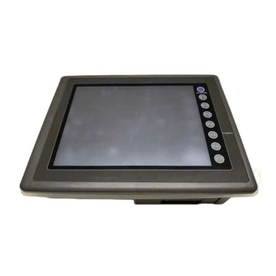
4 Names of Components 1 - 11 Names of Components Front Side of UG220 Rear Side of UG220 DC24V Front Side of UG221 Rear Side of UG221 24VDC Front Side of UG320 Rear Side of UG320 DC24V Mounting holes for fixtures Dip switches Display MJ1, 2: for data transfer, for temperature... - Page 21 1 - 12 4 Names of Components Front Side of UG420 Rear Side of UG420 100- 240VAC Front Side of UG520 Rear Side of UG520 100- 240VAC Mounting holes for fixtures MJ1, 2: for data transfer, for temperature controller, for bar-code reader, for UG00P-MR Display and for UG00P-U2 (option) Function keys (Refer to P1-59)
-
Page 22: Dimensions And Panel Cut-Out
5 Dimensions and Panel Cut-out 1 - 13 Dimensions and Panel Cut-out Dimensions of UG220 Unit : mm Top View Rear View 173.6 Front View Side View 117.2 182.5 Panel Cut-out of UG220 Unit : mm +0.5... - Page 23 1 - 14 5 Dimensions and Panel Cut-out Dimensions of UG221 Unit : mm Side View Front View SYSTEM POWER 182.5 Rear View Under View 24V DC Do not remove this seal. unless the optional unit is mounted. Panel Cut-out of UG221 Unit : mm...
- Page 24 5 Dimensions and Panel Cut-out 1 - 15 Dimensions of UG320 Unit : mm Top View Rear View DC 24V Front View Side View Panel Cut-out of UG320 Unit : mm +0.5 220.5...
- Page 25 1 - 16 5 Dimensions and Panel Cut-out Dimensions of UG420 Unit : mm Rear View Top View 100- 240VAC Front View Side View Panel Cut-out of UG420 Unit : mm +0.5...
- Page 26 5 Dimensions and Panel Cut-out 1 - 17 Dimensions of UG520 Unit : mm Top View Rear View 100- 240VAC Front View Side View Panel Cut-out of UG520 Unit : mm +0.5...
-
Page 27: Mounting Procedure
1 - 18 6 Mounting Procedure Mounting Procedure Mounting Procedure Cut out the mounting panel (Max. thick: 3.2 mm) to match the dimensions shown below. Mounting panel Unit : mm 220.5 +0.5 +0.5 Cut-out UG220 UG320 UG221 +0.5 +0.5 UG420 UG520 Insert the fixtures attached to UGx20 into the mounting holes on UGx20. -
Page 28: Wiring
7 Wiring 1 - 19 Wiring Caution • Do not remove the dust-proof seal till you finish wiring in the panel. If the seal is removed, conductor chips or other foreign matter may enter the device to cause failure. • When you finished wiring in the panel, be sure to remove the dust-proof seal. - Page 29 1 - 20 7 Wiring Grounding This equipment must be earthed. other UGx20 equipment An independent earth pole shall be used for POD. (The level of grounding resistance should be less than 100 .) Use a cable which has a nominal cross section of more than for grounding.
-
Page 30: Specifications
8 Specifications 1 - 21 Specifications General Specifications Type UG221 UG220 UG320 Item Rated Voltage 24V DC Permissible Range 10% DC of Voltage 10ms or less Permissible Momentary Power Failure 20W or less Demand 10W or less Rushed Electric Current 1.5ms With-stand voltage DC external terminals to FG : 500V AC per min. - Page 31 1 - 22 8 Specifications UG420 UG520 Type Item AC Power Supply DC Power Supply AC PowerSupply DC Power Supply Rated Voltage 24V DC 100/240V AC 24V DC 100/240V AC Permissible Range 10% DC 85 to 265V AC 10% DC 85 to 265V AC of Voltage (47 to 440Hz)
-
Page 32: Display Specifications
8 Specifications 1 - 23 Display Specifications Type UG320H UG220H-L UG220H-S UG221H-L UG221H-S UG221H-T Item Display Device Monochrome Color Monochrome Color Color Color Resolution W H (dots) 0.082 0.246 0.36 0.36 0.12 0.36 0.36 0.36 0.12 0.36 Dot Pitch W H (mm) 0.36 0.36 157.4 118.1... - Page 33 1 - 24 8 Specifications Display Function Specifications (All the UGx20 series) Item Specifications Display Language Japanese Eng./W. Europe Chinese Chinese (simplified) Korean Characters ANK code ASCII code ASCII code ASCII code ASCII code 1/4-size, 1-byte JIS 1st and 2nd ASCII code Chinese Chinese (simplified)
- Page 34 8 Specifications 1 - 25 Function Performance Specifications (All the UGx20 series) Specifications Item Max. 1024 Screens FP-ROM (flash memory), Appox. 2,816Kbytes (different from the language) Screen Memory 768 per screen (192 per screen for UG221/220 : However, the number of Switches memory settings is limited.) Actions of Switch...
- Page 35 1 - 26 8 Specifications Touch Panel Specifications (All the UGx20 series) Item Specifications Switch Resolution Analog, 1024(W) 1024(H) Matrix type, UG221: 20(W) 12(H) pcs Form Resistance film form Life of Touch Panel Use of one million times or more Function Switch Specifications (All the UGx20 series) Item Specifications...
-
Page 36: Serial Connector (Cn1)
9 Serial Connector (CN1) 1 - 27 Serial Connector (CN1) CN1 is used for communicating between a PLC and a POD(RS-232C, RS-422/485). Serial Connector (CN1) The pin arrangement of serial connector is as follows: Pin No. Signal Contents Frame ground RS-232C send data RS-232C receive data 100-... - Page 37 1 - 28 9 Serial Connector (CN1) RS-422 In case of RS-422, +SD and -SD, and +RD and -RD form a pair. Use SG if possible. Connect the shielded cable to pin No. 1 or the connector case cover. Use UG00P-TC which is the optional equipment made by Fuji Electric. Co., Ltd. in case of using terminal blocks in RS-422/485 connection.
-
Page 38: Setting Of Dip Switches
10 Setting of Dip Switches 1 - 29 Setting of Dip Switches Setting of Dip Switches (DIPSW) Terminal resistance of MJ2(modular jack 2) Memory Extension 2 But, it depends on a hardware version. (invalid for UG220) Not used RD terminal resistance of pin No. 24 and 25 Terminal resistance of MJ1(modular jack 1) Keep DIPSW 2, 3, 4 and 5 (not used) OFF. -
Page 39: Modular Jack 1 & 2
1 - 30 11 Modular Jack 1 & 2 Modular Jack 1 & 2 Modular Jack 1 & 2 (MJ1/2) MJ1/2 Pin No. Signal Contents + SD/RD RS-485 + data The right diagram is the pin arrangement and the - SD/RD RS-485 - data signal name of modular jack 1 &... -
Page 40: Bar Code Reader Interface
12 Bar Code Reader Interface 1 - 31 Bar Code Reader Interface It is possible to receive the signal from a bar code reader by connecting a bar code reader to POD via the modular jack (MJ1/MJ2) of POD series. To connect a bar code reader to POD via MJ1/MJ2, use the cable which is the optional equipment made by Fuji Electric. -
Page 41: Printer Interface (Cn2)
1 - 32 13 Printer Interface (CN2) Printer Interface (CN2) When a printer is connected to POD via the connector (CN2), it is possible to hard-copy the screen display of POD, the data sheet, or the sampling data. To connect a printer to POD, use the parallel interface cable of 36 pins which is optional equipment made by Fuji Electric. -
Page 42: Video Interface
14 Video Interface 1 - 33 Video Interface (Option: UG520/UG420 only) When a video or a CCD camera is connected to the optional UGx20 which has a video interface, the image which is taken by a video or a camera is displayed directly in a screen of UGx20 series (only in case of UG520H-V and UG420H-T/V). -
Page 43: Analog Rgb Input
1 - 34 15 Analog RGB Input Analog RGB Input (Option: UG420H-T only) When connector CN3 of UG420H-TC (analog RGB input adapted product) is connected to a personal computer, the screen image of the personal computer can be displayed on the UG420H-TC. Connector pin layout [high density D-sub 15-pin connector (female Input signal... - Page 44 15 Analog RGB Input 1 - 35 Touch-switch emulation function With this function, you can manipulate the Windows screen displayed on the POD with touch switches, i.e. without using the mouse. Applicable version of screen development editor This function is adapted to 2.4.0.0 or newer versions of the screen development editor. Applicable version of POD system program This function is adapted to 1.200 or newer versions of POD system program (SYSTEM PROG.VER.) Touch panel driver to be installed...
- Page 45 1 - 36 15 Analog RGB Input 4. Save the file, and send it to the POD. 5. Mode is changed to RUN. In this mode, change screen over to the [RGB Input] screen. (Windows screen is displayed.) DOS/V Personal 6.
-
Page 46: Connection
16 Connection 1 - 37 Connection 1 : 1 Link Communication One POD and one PLC are connected. • • • • • • • • • • • • • • • • • • • • • • • • s t o p •... - Page 47 1 - 38 15 Connection Multi-drop Communication (RS-485) Refer to the PLC manual of each manufacturer for connection. <E.g.> The following example describes how one POD is connected to three PLCs made by MITSUBISHI. See MITSUBISHI’s manual for further details. POD (CN1) Link unit Link unit...
- Page 48 16 Connection 1 - 39 <Type> <Calendar> <Type> <Calendar> FUJI : MICREX-F series Depends on the model A.B : Micro Logix 1000 Not provided GE Fanuc : 90 series Not provided FUJI : MICREX-SX series Provided GE Fanuc : 90 series(SNP-X) Not provided FUJI : MICREX-SX CPU Provided...
- Page 49 1 - 40 16 Connection n : 1 Link Communication (Multi-link) Multiple POD and a PLC are connected. (n=1 to 32) POD 1 POD 2 POD 3 POD n The connections shown below are not recommended. RS-485 Maximum length 500m (from PLC to the last •...
- Page 50 16 Connection 1 - 41 When multiple POD are connected to a link unit of PLC, use the terminal converter (UG00P-TC), the optional equipment made by Fuji Electric. Co., Ltd. for RS-485 connection. • Set the dip switch (SW1) of UG00P-TC as 2-wire connection when the UG00P-TC terminal converter is used. POD + UG00P-TC POD + UG00P-TC POD + UG00P-TC...
-
Page 51: Operation Of Pod Main Menu
1 - 42 17 Operation of POD Main Menu Operation of POD Main Menu When the power of POD is turned on for the first time, the screen on the below left is displayed. After transferring the screen data to POD, the following “Main Menu” is displayed. When power is turned on for the first time: "Main Menu"... - Page 52 17 Operation of POD Main Menu 1 - 43 System program version Model name of POD Font data version Data size Main Menu UG420H-TC1M1 Main Menu 1998- 9- 1 7 : 23 : 30 System Information System Information FONT I/F DRV VER. 1.000 VER.1.000/1.000/1.000 MELSEC AnA/N/U SYSTEM PROG.
- Page 53 1 - 44 17 Operation of POD Main Menu I/O Test When the switch “a” on the “Main Menu” is pressed, the following “I/O Test” is displayed. This is the test menu to check only POD hardware. I/O Test Memory-Card Press the [I/O Test] switch.
- Page 54 17 Operation of POD Main Menu 1 - 45 A. Self-loop Test This is the test menu to check the signals necessary for UG20 to communicate with PLC or a personal computer by using only POD. Signal Test of RS-232C in CN1 Select [CN1] and [RS-232C] in [Communication Port] by pressing each switch.
- Page 55 1 - 46 17 Operation of POD Main Menu Signal Test of RS-485 in CN1 Select [CN1] and [RS-485] in [Communication Port] by pressing each switch. Communication Port RS-232C RS-485 • Loop-back Test Check the signals, [SD] and [RD]. Jump each pin, 12 and 24, 13 and 25 of CN1. The test is OK, if the [OK] lamp turns on when the [Self-Loop Test] switch is pressed.
- Page 56 17 Operation of POD Main Menu 1 - 47 Signal Test of RS-232C in MJ1 and MJ2 Select [MJ1] (or [MJ2]) and [RS-232C] in [Communication Port] by pressing each switch. Communication Port RS-232C RS-485 • Loop-back Test Check the signals, [SD] and [RD]. Execute the test by connecting the data transfer cable (UG00C-T) to CN1.
- Page 57 1 - 48 17 Operation of POD Main Menu B. Printer Check Check the signal of printer. The test is OK if the test printout is executed satisfactorily when connecting POD to a printer and pressing this [Printer Check] switch. !"#$%&@ 0123456789 ABCDEFGHIJKLMNO !"#$%&@ 0123456789 ABCDEFGHIJKLMNO !"#$%&@ 0123456789 ABCDEFGHIJKLMNO...
- Page 58 17 Operation of POD Main Menu 1 - 49 In case of matrix type When pressing the [Switch Check] switch, the following screen which is divided by a minimum size of switch is displayed. Confirm that the color of the pressed switch changes into white. Pressing the corner right below leads to the previous [I/O Test] screen.
- Page 59 1 - 50 17 Operation of POD Main Menu Memory-Card When the [Memory-Card] switch on the “Main Menu” is pressed, the following “Memory-Card” is displayed. This screen is to transfer the screen data between POD and a memory-card. I/O Test Memory-Card The "Memory-Card"...
- Page 60 17 Operation of POD Main Menu 1 - 51 2)Data Selection, Transfer Pressing each switch leads to selection of the target for data transferring. (Possible to select multiple items.) Data Selection Transfer Memory-Card Memory-Card Main Menu Main Menu Close Close Memory-Card Information Memory-Card Information Memory-Card Information...
- Page 61 1 - 52 17 Operation of POD Main Menu Message Display in Data Transferring Work nomally finished. If an error occurs during transferring data, the message display window shown on the right is displayed. The kinds and the contents of the messages are as shown below. Message Contents Work normally finished.
- Page 62 17 Operation of POD Main Menu 1 - 53 Screen Adjustment [Option: UG420H-T(RGB input adapted product) only] Depending on what type of personal computer is used, RGB output frequency for Windows screen, BIOS screen or DOS screen changes. Therefore, adjustment is necessary. When there is only one type of output frequency, select either “Setting 1”...
- Page 63 1 - 54 17 Operation of POD Main Menu First, BIOS screen is adjusted. Press the [Adjust] switch in the [Setting 1] box to activate RGB display mode. RGB Adjust Main Menu Please refer to the manual, "Hardware". Horizontal : 31180 Hz Vertical : 59 Hz Setting-1 Setting-2...
- Page 64 17 Operation of POD Main Menu 1 - 55 Then the Windows screen is adjusted. Press the [Adjust] switch in the [Setting 2] box to activate RGB display mode. RGB Adjust Main Menu Please refer to the manual, "Hardware". Horizontal : 31180 Hz Vertical : 59 Hz Setting-1 Setting-2...
- Page 65 1 - 56 17 Operation of POD Main Menu Press the [Save] switch to save the setting data. (The setting data is written in the flash ROM.) RGB Adjust Main Menu Please refer to the manual, "Hardware". Horizontal : 31180 Hz Vertical : 59 Hz Setting-1 Setting-2...
- Page 66 17 Operation of POD Main Menu 1 - 57 Setting for SRAM cassette When the optional SRAM cassette (UG00P-SR, UG221P-SR) is installed in the POD main unit, it is possible to adjust the internal calendar of the SRAM cassette or to format the SRAM cassette. Adjusting the internal calendar of SRAM cassette (Main Menu) 1)Activate the [Main Menu] screen.
-
Page 67: Function Switches
1 - 58 18 Function Switches Formatting the SRAM cassette When you changed the setting of SRAM cassette area, be sure to format the SRAM cassette. SRAM cassette can be formatted from the [Main Menu] screen. If the format of the SRAM cassette does not coincide with the setting of screen data, the SRAM cassette cannot be used (error No. -
Page 68: Function Switches
17 Operation of POD Main Menu 1 - 59 Function Switches Type [SYSTEM], [F1], [F2], [F3], [F4], [F5], [F6], [F7] (UG221, UG220 : [SYSTEM], [F1] ~ [F5]) the [SYSTEM] switch By pressing this switch, the functions of the switches [F1] ~ [F7] are defined. The type of the [SYSTEM] switch is alternate. -
Page 69: Connection To Link Units
Connection to Link Units 1. FUJI PLC • 1 40. KEYENCE PLC• 1 2. FUJI PLC • 2 41. KEYENCE PLC• 2 3. FUJI PLC • 3 42. KEYENCE PLC• 3 4. FUJI PLC • 4 43. LG PLC 5. FUJI PLC • 5 44. -
Page 70: Fuji Plc • 1
• 1 FUJI PLC 2 - 1 FUJI PLC • 1 (MICREX-F series) Available PLC Select PLC Type Link Unit Wiring Diagram NV1L-RS2 RS-232C [Wiring Diagram 1] RS-232C [Wiring Diagram 1] NC1L-RS2 F70, F70S NC1L-RS4 RS-485 [Wiring Diagram 2] MICREX-F Series FFU120B RS-232C [Wiring Diagram 1]... - Page 71 2 - 2 • 1 FUJI PLC Available Memory Memory TYPE Remarks (auxiliary relay) WM as word device (keep relay) WK as word device (input/output relay) WB as word device (link relay) WL as word device (special relay) WF as word device (Read only) (timer/set value) (timer/current value) W9 (timer/current value 0.1)
- Page 72 • 1 FUJI PLC 2 - 3 • When you access the file memory from the POD, be sure to define FILE instruction on the PLC side. File type must be SI (16-bit length). Communication with file memories that are defined by BD, DI, etc.
-
Page 73: Fuji Plc • 2
2 - 4 • 1 FUJI PLC FUJI PLC • 2 (MICREX-SX series) Available PLC Wiring Diagram Select PLC Type Link Unit RS-232C [Wiring Diagram 1] NP1L-RS1 SPH Series RS-485 [Wiring Diagram 2] MICREX-SX (NP1PS- x ) Series RS-232C [Wiring Diagram 1] NP1L-RS2 RS-485 [Wiring Diagram 2] NP1L-RS4... - Page 74 • 2 FUJI PLC 2 - 5 Wiring The following is a diagram to show the wiring of the cable which connects POD to PLC. RS-232C Wiring Diagram 1 POD (CN1) D-sub 25pin(Male: D-sub 9pin(Male: Use twist shielded cables. RS-485 Wiring Diagram 2 D-sub 9pin(Female: POD (CN1)
-
Page 75: Fuji Plc • 3
2 - 6 • 2 FUJI PLC FUJI PLC • 3 (MICREX-SX CPU Port) Available PLC Select PLC Type Connected Cable MICREX-SX MICREX-SX Loader Port UG00C-Sx When the CPU is updated, or the specifications are changed, there is some possibility that POD cannot be connected to the PLC. - Page 76 • 3 FUJI PLC 2 - 7 Notes on the direct connection with the CPU port of SX series CPU • Fully consider the influence of noise on the communication cable routed between the POD and MICREX-SX. (The level of noise resistance when a ferrite core is attached to the cable: 1,000 V) •...
-
Page 77: Fuji Plc • 4
2 - 8 • 3 FUJI PLC FUJI PLC • 4 (FLEX-PC series) Available PLC Wiring Diagram Select PLC Type Link Unit RS-232C [Wiring Diagram 1] NS Series, NS-T NS-RS1 RS-485 [Wiring Diagram 2] FLEX-PC NJ-RS2 RS-232C [Wiring Diagram 1] Series NJ Series, NJ-T NJ-RS4... - Page 78 • 4 FUJI PLC 2 - 9 Switch Setting MODE Switch: RS-232C: 1 RS-485: 3 RS-485 Port Setting SW: “0” for both RS-485 Terminal Resistor: ON Character Switches Setting Contents Switch setting Parity provided Even 7 bit 1 bit Same as POD (normally 19200bps) Available Memory Standard Memory...
- Page 79 2 - 10 • 4 FUJI PLC Wiring The following is a diagram to show the wiring of the cable which connects POD to PLC. RS-232C Wiring Diagram 1 POD (CN1) D-sub 25pin(Male: D-sub 25pin(Male: Use twist shielded cables. RS-485 Wiring Diagram 2 POD (CN1) D-sub 25pin(Male:...
-
Page 80: Fuji Plc • 5
• 4 FUJI PLC 2 - 11 FUJI PLC • 5 (FLEX-PC CPU port) Available PLC Select PLC Type Wiring Diagram FLEX-PC Loader Port RS-422 [UG200C-N] FLEX-PC NJ-B16 RS-232C Port RS-232C [Wiring Diagram 1] When FLEX-PC CPU TOYOTA version is used, select “FLEX-PC CPU(T)” in [PLC Type]. When the CPU is updated, or the specifications are changed, there is some possibility that POD cannot be connected to the PLC. - Page 81 2 - 12 • 5 FUJI PLC Wiring • Fully consider the influence of noise on the communication cable routed between the POD and FLEX-PC. (The level of noise resistance when a ferrite core is attached to the cable: 1,000 V) •...
- Page 82 • 5 FUJI PLC 2 - 13 Wiring The following is a diagram to show the wiring of the cable which connects POD to PLC. RS-422 Wiring Diagram 1 ( connection of the UG200C-N ) POD (CN1) D-sub 25pin(Male: + RD + SD - RD - SD...
-
Page 83: Fuji Plc • 6
2 - 14 • 5 FUJI PLC FUJI PLC • 6 (TOYOTA version NJ Computer Link) Available PLC Wiring Diagram Select PLC Type FLEX-PC Computer link RS-422 [Wiring Diagram 1] of FLEX-PC NJ-JM Connect to the terminal block of the NJ-JM computer link. For further information, refer to the PLC manual. - Page 84 • 6 FUJI PLC 2 - 15 Available Memory Memory TYPE Remarks (data register) (link register) (internal relay) WM as word device (latch relay) WK as word device (input relay) WX as word device (output relay) WY as word device (file register) (timer/current value) Read only...
- Page 85 2 - 16 • 7 MITSUBISHI PLC MITSUBISHI PLC • 1 (A/Q series link unit) Available PLC Wiring Diagram Link Unit Select PLC Type AJ71C24-S6 A2A, A3A AJ71C24-S8 AJ71UC24 AJ71UC24 A2U, A3U, A4U RS-232C [Wiring Diagram 2] AJ71C24 RS-422 [Wiring Diagram 3] A1, A2, A3 AJ71C24-S3 A1N, A2N, A3N...
- Page 86 • 7 MITSUBISHI PLC 2 - 17 Communication Setting The recommended communication parameter setting of both PLC and POD is as follows: A series link unit Item Setting of PLC Comm. Parameter of POD Baud Rate 19200bps 19200bps Port 0 for both STATION x10 and x1 Parity Even Even...
- Page 87 2 - 18 • 7 MITSUBISHI PLC Be sure to check these items. Check that these settings are the same as POD comm. parameters. Switch Setting The following is an example to show the settings for both rotary dip switches and dip switches on PLC. <E.g.1>...
- Page 88 • 7 MITSUBISHI PLC 2 - 19 <E.g. 4> Signal Level: RS-422, Baud Rate: 19200bps, Trans. Mode: Trans. Mode 1 A1SJ71UC24-R4 SW01 A1SJ71C24-R4 SW02 STATION No STATION No MODE SW03 B C D E B C D E B C D E SW04 SW05 SW06...
- Page 89 2 - 20 • 7 MITSUBISHI PLC Wiring The following is a diagram to show the wiring of the cable which connects POD to PLC. RS-232C Wiring Diagram 1 POD (CN1) D-sub 25pin(Male: D-sub 9pin(Male: Use twist shielded cables. Wiring Diagram 2 POD (CN1) D-sub 25pin(Male: D-sub 25pin(Male:...
- Page 90 • 7 MITSUBISHI PLC 2 - 21 RS-422 Wiring Diagram 3 POD (CN1) D-sub 25pin(Male: + SD - SD + RD - RD Use twist shielded cables. Wiring Diagram 4 POD (CN1) D-sub 25pin(Male: D-sub 25pin(Male: + SD - SD DSRA + RD DTRA...
- Page 91 2 - 22 • 7 MITSUBISHI PLC MITSUBISHI PLC • 2 (A/QnA series CPU ) Connection Connect to the A/Q series CPU port. The communication parameter setting of POD is done automatically. Available PLC Wiring Diagram Select PLC Type A2A, A3A A2U, A3U, A4U A2US(H) A1N, A2N, A3N...
- Page 92 • 8 MITSUBISHI PLC 2 - 23 Available Memory Memory TYPE Remarks (data register) (link register) (file register) (timer/current value) CN (counter/current value) SPU (special unit) Unit No. (internal relay) (latch relay) (link relay) (input relay) (output relay) (timer/contact) (timer/coil) CS (counter/contact) CC (counter/coil) SD (special register)
- Page 93 2 - 24 • 8 MITSUBISHI PLC Wiring The following is a diagram to show the wiring of the cable which connects POD to PLC. (connection of the UG200C-M) RS-422 Wiring Diagram 1 POD (CN1) D-sub 25pin(Male: D-sub 25pin(Male: + RxD + SD + TxD - SD...
- Page 94 • 8 MITSUBISHI PLC 2 - 25 Notes on using UG00P-DI (Dual Port Interface) As the UG00P-DI is powered by a CPU, check that the electric capacity of the CPU is at 5V (power consumption: max. 350mA). The distance between the CPU and the UG00P-DI should be as short as possible (max. 1 to 1.5m). For wiring, take appropriate measures to eliminate noise.
- Page 95 2 - 26 • 8 MITSUBISHI PLC MITSUBISHI PLC • 3 (QnH series CPU) Connection Connect to the QnH series CPU. The communication parameter setting of POD is done automatically. Available PLC Wiring Diagram Select PLC Type QnH(A) series CPU Q06H-A RS-232C [UG00C-Q] Q02, [Wiring Diagram 1]...
- Page 96 • 9 MITSUBISHI PLC 2 - 27 Available Memory Memory TYPE Remarks (data register) (link register) (file register) (timer/current value) CN (counter/current value) SPU (special unit) Unit No. (internal relay) (latch relay) (link relay) (input relay) (output relay) (timer/contact) (timer/coil) CS (counter/contact) CC (counter/coil) SD (special register)
- Page 97 2 - 28 • 10 MITSUBISHI PLC MITSUBISHI PLC • 4 (FX / FX2N / FX1S series CPU) Connection Connect to the FX series CPU port. The communication parameter setting of POD is done automatically. Available PLC Select PLC Type Wiring Diagram RS-232C [UG00C-X] made by Fuji Electric FX1/2...
- Page 98 • 10 MITSUBISHI PLC 2 - 29 Available Memory FX1/2, FX0N, FX1S series CPU Memory TYPE Remarks (data register) (timer/current value) CN (counter/current value) 32CN (counter 32bits) (internal relay) (state) (input relay) Read only (output relay) (timer/contact) CS (counter/contact) DX (Data register) In case of the items which can display double word data (e.g.
- Page 99 2 - 30 • 10 MITSUBISHI PLC Wiring The following is a diagram to show the wiring of the cable which connects POD to PLC. RS-232C Use the cable, “UG00C-X”(3m), made by Fuji Electric Co., Ltd. in case of RS-232C connection. RS-422 Wiring Diagram 1 (connection of the UG200C-M) POD (CN1)
- Page 100 • 10 MITSUBISHI PLC 2 - 31 Notes on using UG00P-DI (Dual Port Interface) As the UG00P-DI is powered by a CPU, check that the electric capacity of the CPU is at 5V (power consumption: max. 350mA). The distance between the CPU and the UG00P-DI should be as short as possible (max. 1 to 1.5m). For wiring, take appropriate measures to eliminate noise.
- Page 101 2 - 32 • 11 MITSUBISHI PLC MITSUBISHI PLC • 5 (FX series link [A prt] ) Available PLC Select PLC Type Link Unit Wiring Diagram RS-232C [Wiring Diagram 1] FX2N-232-BD FX2N RS-485 [Wiring Diagram 3] FX2N-485-BD RS-422 [ UG00C-E ] made by Fuji Electric FX2N-422-BD RS-232C [Wiring Diagram 1] FX1N-232-BD...
- Page 102 • 11 MITSUBISHI PLC 2 - 33 Available Memory Memory TYPE Remarks (data register) (timer/current value) CN (counter/current value) 32CN (counter 32bits) (internal relay) (state) (input relay) Read only (output relay) (timer/contact) CS (counter/contact) The meaning of CN200~CN255 is the same as the meaning of 32CN(counter 32bits). In case of the items which can display double word data (e.g.
- Page 103 2 - 34 • 11 MITSUBISHI PLC Wiring The following is a diagram to show the wiring of the cable which connects POD to PLC. RS-232C Wiring Diagram 1 POD (CN1) D-sub 25pin(Male: D-sub 9pin(Female: Use twist shielded cables. Wiring Diagram 2 POD (CN1) D-sub 25pin(Male: D-sub 25pin(Male:...
- Page 104 • 12 MITSUBISHI PLC 2 - 35 MITSUBISHI PLC • 6 (A Link + Net 10) POD can access other CPUs on the NET II(/B) or NET/10 when POD is connected to one of the link units that the data link system or network system consists of. Select “A Link + Net10”...
- Page 105 2 - 36 • 12 MITSUBISHI PLC Macro type to specify network • • • • • • • • • • • • • • • • • • • • • • • • • • • • [OUT_ENQ] command of [SYS] F1 Memory 0 (fixed) Specify network: 2 (fixed)
-
Page 106: Omron Plc • 1
• 13 OMRON PLC 2 - 37 OMRON PLC • 1 (C/CV/CS1 series) Available PLC Select PLC Type Link Unit Wiring Diagram CPU unit with a built-in C20H, C28H, C40H RS-232C [Wiring Diagram 1] RS-232C port (host link port) C120, C120F C200H C120-LK201-V1 RS-232C [Wiring Diagram 3]... - Page 107 2 - 38 • 13 OMRON PLC Communication Setting The recommended communication parameter setting of both PLC and POD is as follows: Item Setting of PLC Comm. Parameter of POD Baud Rate 19200bps 19200bps Port Parity Even Even Data Length 7 (ASCII) Transmission Code...
- Page 108 • 13 OMRON PLC 2 - 39 Available Memory Memory TYPE Remarks DM (data memory) CH (input/output relay) HR (holding relay) (latch relay) AR (alarm relay) (timer/current value) (counter/current value) EMn (extensional data memory) (timer/contact) Read only CU (counter/contact) Read only Memory TYPE Remarks...
- Page 109 2 - 40 • 13 OMRON PLC Wiring The following is a diagram to show the wiring of the cable which connects POD to PLC. RS-232C Wiring Diagram 1 POD (CN1) D-sub 25pin(Male: D-sub 9pin(Male: Use twist shielded cables. Wiring Diagram 2 POD (CN1) D-sub 25pin(Male: D-sub 9pin(Male:...
- Page 110 • 13 OMRON PLC 2 - 41 RS-422 Wiring Diagram 4 POD (CN1) D-sub 25pin(Male: D-sub 9pin(Male: + SD - SD + RD - RD Use twist shielded cables. Wiring Diagram 5 POD (CN1) D-sub 25pin(Male: D-sub 9pin(Male: + SD - SD + RD - RD...
-
Page 111: Omron Plc • 2
2 - 42 • 14 OMRON PLC OMRON PLC • 2 (OMRON-CS1 DNA) When connect the POD to CS1 on a network, the POD can also (2-2) (1-2) access the other CS1 on a network. Network No.1 (1-3) Network No.2 (2-1) (2-3) (1-1) -
Page 112: Sharp Plc • 1
• 15 Sharp PLC 2 - 43 Sharp PLC • 1 Available PLC Link Unit Wiring Diagram Select PLC Type W50, JW70, JW100 ZW-10CM RS-422 [Wiring Diagram 3] JW50H, JW70H JW-10CM JW100H series JW20 JW-21CM RS-422 [Wiring Diagram 3] JW-31CUH JW70, JW100 JW100/70H JW70H, JW100H... - Page 113 2 - 44 • 15 Sharp PLC Switch Setting of Link Unit Baud rate: 19200bps Swtich Setting Contents Command mode Station address (lower half) Station address (upper half) SW3-1 Not used SW3-2 4-wire system SW3-3 Not used SW3-4 Even parity Baud rate 0: 19200 1: 9600 2: 4800 3: 2400 4: 1200...
- Page 114 • 15 Sharp PLC 2 - 45 Wiring The following is a diagram to show the wiring of the cable which connects POD to PLC. RS-232C Wiring Diagram 1 POD (CN1) D-sub 25pin(Male: D-sub 15pin(Male: Use twist shielded cables. RS-422 Wiring Diagram 2 POD (CN1) D-sub 25pin(Male:...
-
Page 115: Sharp Plc • 2
2 - 46 • 16 Sharp PLC Sharp PLC • 2 (JW-32CUH/33CUH) Available PLC Wiring Diagram Link Unit Select PLC Type RS-232C PG/COMM2 [Wiring Diagram 1] JW20 JW-32CUH Communication port RS-422 COM port JW-33CUH on a CPU unit PG/COMM1 [Wiring Diagram 2] PG/COMM2 [Wiring Diagram 2] Communication Setting The recommended communication parameter setting of both PLC and POD is as follows:... - Page 116 • 16 Sharp PLC 2 - 47 1 To set up Fn (file register), input [File No.] + [: (colon)] + [address]. <E.g.> F1 : 00002 Address Colon File No. Set the memory to the extent of the memory range of each PLC model. Use TYPE number to assign indirect memory for macro programs.
-
Page 117: Hitachi Plc • 1
2 - 48 • 17 HITACHI PLC HITACHI PLC • 1 (HIDIC H series) Available PLC Select PLC Type Wiring Diagram Link Unit RS-232C [Wiring Diagram 1] COMM-2H RS-422 [Wiring Diagram 2] PERIPHERAL port RS-232C [Wiring Diagram 1] on a CPU module HIDIC H series CPU HIDIC-H *1 [EH-RS05] cable made by HITACHI... - Page 118 • 17 HITACHI PLC 2 - 49 Switch Setting Baud rate : 19200bps MODE switch : To connect to both RS-232C and RS-422, set MODE switch to 9. RS-232C(pattern 2, w/o) RS-422(pattern 2, with port) ST No. switch : Choose “0” for both 10 and Dip Switch Switch...
- Page 119 2 - 50 • 17 HITACHI PLC Wiring The following is a diagram to show the wiring of the cable which connects POD to PLC. RS-232C Wiring Diagram 1 POD (CN1) D-sub 25pin(Male: D-sub 15pin(Male: PV12 Use twist shielded cables. RS-422 Wiring Diagram 2 POD (CN1)
-
Page 120: Hitachi Plc • 2
• 18 HITACHI PLC 2 - 51 HITACHI PLC • 2 (HIDIC-S10 Available PLC Host Link H-7338 Link Unit Wiring Diagram Select PLC Type S10 2 Interface on a CPU unit RS-422 [Wiring Diagram 3] HIDIC-S10/2alpha RS-422 [Wiring Diagram 3] Interface on a CPU unit S10 mini RS-232C [Wiring Diagram 1]... - Page 121 2 - 52 • 18 HITACHI PLC E (event register) EW as word device S (system register) SW as word device (transfer register) JW as word device Q (receive register) QW as word device M (extension input register) MW as word device HIDIC ABS Memory TYPE...
- Page 122 • 18 HITACHI PLC 2 - 53 Wiring Diagram 2 POD (CN1) D-sub 9pin(Female: D-sub 25pin(Male: Use twist shielded cables. RS-422 Wiring Diagram 3 For connection to the S10x series, use a 50 (1/2W) resistance as shown below. POD (CN1) D-sub 25pin(Male: + SD UTX H...
-
Page 123: Matsushita Plc
2 - 54 19 Matsushita PLC Matsushita PLC Available PLC Select PLC Type Link Unit Wiring Diagram RS-232C port RS-232C [Wiring Diagram 1] on a CPU unit RS-232C [Wiring Diagram 1] AFP3462 RS-422 [Wiring Diagram 4] AFP3463 RS-232C [Wiring Diagram 1] AFP5462 RS-232C port RS-232C [Wiring Diagram 1]... - Page 124 19 Matsushita PLC 2 - 55 Switch Setting of Link Unit Setting Contents Same as POD (normally 19200bps) Data length 7 Parity provided Even Stop bit 1 CS, CD invalid Available Memory Memory TYPE Remarks (data register) (external input relay) WX as word device, read only (external output relay) WY as word device...
- Page 125 2 - 56 19 Matsushita PLC Wiring The following is a diagram to show the wiring of the cable which connects POD to PLC. RS-232C Wiring Diagram 1 POD (CN1) D-sub 25pin(Male: D-sub 9pin(Male: Use twist shielded cables. Wiring Diagram 2 POD (CN1) D-sub 25pin(Male: D-sub 9pin(Male:...
-
Page 126: Yokogawa Plc • 1
• 20 YOKOGAWA PLC 2 - 57 YOKOGAWA PLC • 1 (FA-500) Available PLC Link Unit Wiring Diagram Select PLC Type RS-232C [Wiring Diagram 1] LC01-0N FA500 FA500 RS-232C [Wiring Diagram 1] LC02-0N RS-422 [Wiring Diagram 2] Communication Setting The recommended communication parameter setting of both PLC and POD is as follows: Item Setting of PLC Comm. - Page 127 2 - 58 • 20 YOKOGAWA PLC Wiring The following is a diagram to show the wiring of the cable which connects POD to PLC. RS-232C Wiring Diagram 1 POD (CN1) D-sub 25pin(Male: D-sub 25pin(Male: Use twist shielded cables. RS-422 Wiring Diagram 2 POD (CN1) D-sub 25pin(Male:...
-
Page 128: Yokogawa Plc • 2
• 21 YOKOGAWA PLC 2 - 59 YOKOGAWA PLC • 2 ( FA-M3 / FA-M3R ) Available PLC Select PLC Type Link Unit Wiring Diagram Programming tool port Cable made by YOKOGAWA on a CPU module [KM11-2N] FA-M3 FA-M3 RS-232C [Wiring Diagram 1] F3LC01-1N F3LC11-1N RS-232C [Wiring Diagram 1]... - Page 129 2 - 60 • 21 YOKOGAWA PLC Available Memory Memory TYPE Remarks (data register) (common register) (index register) (link register) (special register) (down timer current value) (timer set value) Read only (down counter current value) (down counter set value) (input relay) (output relay) (internal relay) (common relay)
- Page 130 • 21 YOKOGAWA PLC 2 - 61 Wiring The following is a diagram to show the wiring of the cable which connects POD to PLC. RS-232C Wiring Diagram 1 POD (CN1) D-sub 25pin(Male: D-sub 9pin(Male: Use twist shielded cables. RS-422 Wiring Diagram 2 POD (CN1) D-sub 25pin(Male:...
-
Page 131: Yaskawa Plc • 1
2 - 62 • 22 YASKAWA PLC YASKAWA PLC • 1 (memobus) Available PLC Wiring Diagram Select PLC Type Link Unit JAMSC-IF60 RS-232C [Wiring Diagram 1] JAMSC-IF61 JAMSC-IF611 GL60 series JAMSC-IF612 RS-422 [Wiring Diagram 3] JAMSC-IF613 Memobus Memobus port RS-232C [Wiring Diagram 1] on a CPU module GL120, GL130 series... - Page 132 • 22 YASKAWA PLC 2 - 63 Available Memory Memory TYPE Remarks (word device) (input register) Constant register included (link register) (extension register) (coil) (link coil) (input relay) Read only (constant register) Set the memory to the extent of the memory range of each PLC model. Use TYPE number to assign indirect memory for macro programs.
- Page 133 2 - 64 • 22 YASKAWA PLC Wiring Diagram 2 POD (CN1) D-sub 25pin(Male: D-sub 15pin(Male: Use twist shielded cables. RS-422 Wiring Diagram 3 POD (CN1) D-sub 25pin(Male: D-sub 9pin(Male: TXD + + SD RXD + RXD - - SD + RD - RD TXD -...
-
Page 134: Yaskawa Plc • 2
• 23 YASKAWA PLC 2 - 65 YASKAWA PLC • 2 (CP9200SH/MP900) Available PLC Wiring Diagram Select PLC Type Link Unit RS-232C [Wiring Diagram 1] CP-217IF [Wiring Diagram 2] CP9200SH RS-422 [Wiring Diagram 3] CP9200SH Memobus port /MP900 RS-232C [Wiring Diagram 1] on a CPU module MP920, MP930... - Page 135 2 - 66 • 23 YASKAWA PLC Wiring The following is a diagram to show the wiring of the cable which connects POD to PLC. RS-232C Wiring Diagram 1 POD (CN1) CP217IF (CN1) D-sub 25pin (Male: 217IF (CN1/2) D-sub 9pin (Male: Use twist shielded cables.
-
Page 136: Toyopuc Plc
24 TOYOPUC PLC 2 - 67 TOYOPUC PLC Available PLC Link Unit Wiring Diagram Select PLC Type L2/PC2 Series TOYOPUC CMP-LINK RS-422 [Wiring Diagram 1] PC3J Communication Setting The recommended communication parameter setting of both PLC and POD is as follows: Item Setting of PLC Comm. - Page 137 2 - 68 24 TOYOPUC PLC Available Memory Memory TYPE Remarks (data register) (link register) (file register) (current value register) (input relay) WX as word device (output relay) WY as word device (internal relay) WM as word device (keep relay) WK as word device (link relay) WL as word device...
- Page 138 24 TOYOPUC PLC 2 - 69 Wiring The following is a diagram to show the wiring of the cable which connects POD to PLC. RS-422 Wiring Diagram 1 POD (CN1) D-sub 25pin(Male: + SD - SD + RD - RD Use twist shielded cables.
-
Page 139: Koyo Plc
2 - 70 25 Koyo PLC Koyo PLC Available PLC Select PLC Type Wiring Diagram Link Unit RS-232C [Wiring Diagram 1] SU-5/5E/6B/5M/6M U01-DM RS-422 [Wiring Diagram 3] SU-5E/6B RS-232C [Wiring Diagram 1] Port 1 on a CPU unit RS-422 [Wiring Diagram 7] SU-5M/6M Port 3 on a CPU unit RS-485 [Wiring Diagram 8]... - Page 140 25 Koyo PLC 2 - 71 Communication Setting The recommended communication parameter setting of both PLC and POD is as follows: Item Setting of PLC Comm. Parameter of POD Baud Rate 19200bps 19200bps Port "0" for x 10, "1" for x 1 Parity Data Length Transmission...
- Page 141 2 - 72 25 Koyo PLC Switch Setting U-01DM On-line/off-line switch: on-line UNIT ADR switch: “0” for x 10, “1” for x 1 SW4 Dip Switch: Setting Contents Same as POD (normally 19200bps) Parity provided Self-diagnosis Response delay time 0msec SW5 Dip Switch: Setting Contents...
- Page 142 25 Koyo PLC 2 - 73 Wiring The following is a diagram to show the wiring of the cable which connects POD to PLC. RS-232C Wiring Diagram 1 POD (CN1) D-sub 25pin(Male: D-sub 25pin(Male: Use twist shielded cables. Wiring Diagram 2 POD (CN1) D-sub 25pin(Male: D-sub 15pin(Male:...
- Page 143 2 - 74 25 Koyo PLC Wiring Diagram 5 POD (CN1) D-sub 25pin(Male: + SD - SD + RD - RD Use twist shielded cables. Wiring Diagram 6 POD (CN1) D-sub 25pin(Male: D-sub 15pin(Male: RXD - + SD TXD + - SD + RD TXD -...
-
Page 144: Allen-Bradley Plc • 1
• 26 Allen-Bradley PLC 2 - 75 Allen-Bradley PLC • 1 (PLC-5 series) Available PLC Wiring Diagram Select PLC Type Link Unit 1785-KE RS-232C [Wiring Diagram 1] PLC-5 PLC-5 RS-232C [Wiring Diagram 2] 1770-KF2 RS-422 [Wiring Diagram 3] Communication Setting The recommended communication parameter setting of both PLC and POD is as follows: Item Setting of PLC... - Page 145 2 - 76 • 26 Allen-Bradley PLC Available Memory Memory TYPE Remarks (integer) (bit) T.ACC (timer/current value) T.PRE (timer/set value) C.ACC (counter/current value) C.PRE (counter/set value) (input) (output) (status) (timer/control) (counter/control) (control/control) R.LEN (control/data length) R.POS (control/data position) (BCD) (ASCáU) Set the memory to the extent of the memory range of each PLC model.
- Page 146 • 26 Allen-Bradley PLC 2 - 77 SW3 (network link transmission speed) Adjust the setting according to the network you are using. Setting Contents Data highway (57.6k bps) Link transmission speed (19.2k bps) Local/remote selection SW4 (spare) Setting Contents Normally OFF (for expansion) 1770-KF2 SW1 (protocol) Setting...
-
Page 147: Wiring Diagram
2 - 78 • 26 Allen-Bradley PLC SW6 (asynchronous link transmission speed) Set the same speed as POD. Setting Contents 9600bps Diagnosis execution SW7 (network link selection) Switch Setting Contents Peer transmission link SW8 (RS-232C/RS-422 selection) Switch Setting Contents RS232C RS422 Wiring The following is a diagram to show the wiring of the cable which connects POD to PLC. - Page 148 • 26 Allen-Bradley PLC 2 - 79 Wiring Diagram 2 POD (CN1) D-sub 25pin(Male: D-sub 25pin(Female: Use twist shielded cables. RS-422 Wiring Diagram 3 POD (CN1) D-sub 25pin(Male: D-sub 25pin(Female: + SD - SD + RD - RD Use twist shielded cables.
-
Page 149: Allen-Bradley Plc • 2
2 - 80 • 27 Allen-Bradley PLC Allen-Bradley PLC • 2 (SLC500 series •Micro Logix1000) Available PLC Wiring Diagram Select PLC Type Link Unit CPU (Processor module) RS-232C [Wiring Diagram 1] RS-232C channel SLC500 SLC 5/03 or later models RS-232C [Wiring Diagram 2] 1747-KE RS-422 [Wiring Diagram 4] RS-232C program transfer... - Page 150 • 27 Allen-Bradley PLC 2 - 81 Available Memory Memory TYPE Remarks (integer) (bit) (timer/current value) (timer/set value) (counter/current value) (counter/set value) (input) (output) (status) (timer/control) CC (counter/control) (control/control) R.LEN (control/data length) R.POS (control/data position) (BCD) (ASC II) (Float) (String) Set the memory to the extent of the memory range of each PLC model.
- Page 151 2 - 82 • 27 Allen-Bradley PLC 1747-KE Set up the parameters for 1747-KE, using the software specifically designed for this purpose. DF1 Port Setup Menu Baudrate : 19200 Bits Per Character Parity : Even Stop Bits DF1 Full-Duplex Setup Parameters Duplicate Packet Detection : Enabled Checksum...
- Page 152 • 27 Allen-Bradley PLC 2 - 83 Wiring Diagram 2 POD (CN1) D-sub 25pin(Male: D-sub 9pin(Female: Use twist shielded cables. Wiring Diagram 3 POD (CN1) D-sub 9pin(Male: D-sub 25pin(Male: AB' RS-232C Ladder transfer cable Micro Logix 1000 * Use twist shielded cables. RS-422 Wiring Diagram 4 POD (CN1)
-
Page 153: Ge Fanuc Plc • 1
2 - 84 • 28 GE Fanuc PLC GE Fanuc PLC • 1 (90 series) Available PLC Select PLC Type Link Unit Wiring Diagram RS-232C [Wiring Diagram 1] Programmable co-processor 90 Series Series 90-30 (PCM) RS-485 [Wiring Diagram 2] Communication Setting The recommended communication parameter setting of both PLC and POD is as follows: Item Setting of PLC... - Page 154 • 28 GE Fanuc PLC 2 - 85 Wiring The following is a diagram to show the wiring of the cable which connects POD to PLC. RS-232C Wiring Diagram 1 POD (CN1) D-sub 25pin(Male: D-sub 25pin(Male: Use twist shielded cables. RS-485 Wiring Diagram 2 POD (CN1)
-
Page 155: Ge Fanuc Plc • 2
2 - 86 • 29 GE Fanuc PLC GE Fanuc PLC • 2 (90 series SNP-X) Available PLC Wiring Diagram Select PLC Type Series 90 micro 90 Series (CPU port) RS-485 [Wiring Diagram 1] (SNP-X) Series 90-30 (CPU port) Communication Setting The recommended communication parameter setting of both PLC and POD is as follows: Item Setting of PLC... - Page 156 • 29 GE Fanuc PLC 2 - 87 Wiring The following is a diagram to show the wiring of the cable which connects POD to PLC. RS-485 Wiring Diagram 1 POD (CN1) D-sub 25pin(Male: D-sub 15pin(Male: RTS(A) + SD - SD CTS(B') + RD - RD...
-
Page 157: Toshiba Plc
2 - 88 30 TOSHIBA PLC TOSHIBA PLC (T series) Available PLC Select PLC Type Wiring Diagram T Series T series RS-422 [Wiring Diagram 1] Communication Setting The recommended communication parameter setting of both PLC and POD is as follows. For further information, refer to the TOSHIBA’s PLC manual. - Page 158 30 TOSHIBA PLC 2 - 89 Available Memory Memory TYPE Remarks (data register) (input register) XW as word device (output register) YW as word device (auxiliary relay) RW as word device (link relay) LW as word device (link register) (file register) (timer/current value) Read only CN (counter/current value)
-
Page 159: Toshiba Machine Plc
2 - 90 31 TOSHIBA MACHINE PLC TOSHIBA MACHINE PLC (TC200) Available PLC Select PLC Type Link Unit Wiring Diagram Port on a CPU unit TC200 TC200 RS-232C [Wiring Diagram 1] TCCMW TCCMO Communication Setting The recommended communication parameter setting of both PLC and POD is as follows. Item Setting of PLC Comm. - Page 160 31 TOSHIBA MACHINE PLC 2 - 91 Wiring The following is a diagram to show the wiring of the cable which connects POD to PLC. RS-232C Wiring Diagram 1 POD (CN1) D-sub 25pin(Male: D-sub 9pin(Female: Use twist shielded cables.
-
Page 161: Siemens Plc • 1
2 - 92 • 32 SIEMENS PLC SIEMENS PLC • 1 (S5-90, S5-95U, S5-100U) Available PLC A similar program as RK512 is required. Wiring Diagram Select PLC Type Link Unit S5-90U CP-521SI RS-232C [Wiring Diagram 1] S5-95U (3964R Transmission Protocol) S5-100U ( S5 UG400 ) [6ES5 734-1BD20] cable made by SIEMENS... - Page 162 • 32 SIEMENS PLC 2 - 93 Notes on converting the data file of UG400 (or UG200) into the UGx20 data file. When converting the data file of UG400 (or UG200) into the UGx20 data file, the PLC type is automatically selected as “SIEMENS S5 UG400.” In UG400 (or UG200) , the order of bytes in I (input relay), Q (output relay) and F (internal relay) is reversed.
-
Page 163: Siemens Plc • 2
2 - 94 • 33 SIEMENS PLC SIEMENS PLC • 2 (S5-115U/135U/155U , S7-300,400) Available PLC A similar program as RK512 is required. Select PLC Type Link Unit Wiring Diagram S5-115U RS-232C [Wiring Diagram 1] CP-524(3964R/RK512) (S5 UG400) S5-135U RS-422 [Wiring Diagram 3] CP-544(3964R/RK512) S5-155U S7-300... - Page 164 • 33 SIEMENS PLC 2 - 95 Notes on converting the data file of UG400 (or UG200) into the UGx20 data file. When converting the data file of UG400 (or UG200) into the UGx20 data file, the PLC type is automatically selected as “SIEMENS S5 UG400.” In UG400 (or UG200) , the order of bytes in I (input relay), Q (output relay) and F (internal relay) is reversed.
-
Page 165: Siemens Plc • 3
2 - 96 • 33 SIEMENS PLC SIEMENS PLC • 3 (S5 PG Port) Connection Connect to the S5 series PG port. The communication parameter setting of POD is done automatically. Available PLC Wiring Diagram Select PLC Type Link Unit Programing port [6ES5 734-1BD20] cable made by SIEMENS S5 PG Port... -
Page 166: Siemens Plc • 4
• 35 SIEMENS PLC 2 - 97 SIEMENS PLC • 4 (S7-200 PPI) Available PLC Select PLC Type Wiring Diagram S7-200 PPI S7-200 series RS-422 [Wiring Diagram 1] Communication Setting The recommended communication parameter setting of both PLC and POD is as follows: Item Setting of PLC Comm. - Page 167 2 - 98 • 35 SIEMENS PLC Wiring The following is a diagram to show the wiring of the cable which connects POD to PLC. RS-422 Wiring Diagram 1 POD (CN1) D-sub 25pin(Male: D-sub 9pin(Male: TXD/RXD TXD/RXD Use twist shielded cables. Setting of Terminal Resistance Set the dip switch 7,8 of POD to OFF.
-
Page 168: Siemens Plc • 5
• 36 SIEMENS PLC 2 - 99 SIEMENS PLC • 5 (TI545, 555) Available PLC Select PLC Type Wiring Diagram RS-232C [Wiring Diagram 1] TI500/505 TI545/555 CPU port (TI500/505 UG400) (built-in) RS-422 [Wiring Diagram 2] Communication Setting Connect the cable to the CPU port (RS-232C built-in port) for TI545/555. The recommended communication parameter setting of both PLC and POD is as follows: Item Setting of PLC... - Page 169 2 - 100 • 36 SIEMENS PLC Notes on converting the data file of UG400 (or UG200) into the UGx20 data file. When converting the data file of UG400 (or UG200) into the UGx20 data file, the PLC type is automatically selected as “TI500/505 UG400.” In UG400 (or UG200), the order of words is reversed when the double words.
-
Page 170: Siemens Plc • 6
• 37 SIEMENS PLC 2 - 101 SIEMENS PLC • 6 (S7-300/400MPI, S7-300/400MPI ADP) Available PLC Adapter Wiring Diagram Select PLC Type S7-300/400MPI S7-300/400 series RS-422 [Wiring Diagram 2] MPI port SIEMENS HMI Adapter S7-300MPI 6ES7 972 0CA11-0XA0 (HMI ADP) S7-300/400 series S7-300MPI SIEMENS PC Adapter... - Page 171 2 - 102 • 37 SIEMENS PLC Available Memory Memory TYPE Remarks DB (data register) Use memories more than DB1. (input relay) IW as word device (output relay) QW as word device (Merker Word) MW as word device (timer/current value) (counter/current value) The assigned memory is indicated while editing the screen as illustrated: <E.g.>...
-
Page 172: Shinko Plc
38 Shinko PLC 2 - 103 Shinko PLC Available PLC Wiring Diagram Select PLC Type Link Unit SELMART-100 or later series Version O1M2-UCI-6x RS-232C [Wiring Diagram 1] SELMART Communication Setting The recommended communication parameter setting of both PLC and POD is as follows: Item Setting of PLC Comm. - Page 173 2 - 104 38 Shinko PLC Wiring The following is a diagram to show the wiring of the cable which connects POD to PLC. RS-232C Wiring Diagram 1 POD (CN1) D-sub 25pin(Male: D-sub 25pin(Male: Use twist shielded cables.
-
Page 174: Samsung Plc
39 SAMSUNG PLC 2 - 105 SAMSUNG PLC (SPC series) Available PLC Wiring Diagram Select PLC Type RS-232C [Wiring Diagram 1] SPC series Series RS-422/485 [Wiring Diagram 2] Communication Setting The recommended communication parameter setting of both PLC and POD is as follows: Item Setting of PLC Comm. - Page 175 2 - 106 39 SAMSUNG PLC Wiring The following is a diagram to show the wiring of the cable which connects POD to PLC. RS-232C Wiring Diagram 1 POD (CN1) D-sub 25pin(Male: D-sub 9pin(Male: Use twist shielded cables. RS-422 Wiring Diagram 2 POD (CN1) D-sub 25pin(Male: D-sub 9pin(Male:...
-
Page 176: Keyence Plc • 1
• 40 KEYENCE PLC 2 - 107 KEYENCE PLC • 1 (KZ series link) Available PLC Link Unit Wiring Diagram Select PLC Type Port 1 RS-232C [Wiring Diagram 1] KZ300 KZ-L2 Port 2 KZ350 Series link RS-232C [Wiring Diagram 2] RS-422 [Wiring Diagram 3] Communication Setting The recommended communication parameter setting of both PLC and POD is as follows:... - Page 177 2 - 108 • 40 KEYENCE PLC Wiring The following is a diagram to show the wiring of the cable which connects POD to PLC. RS-232C Wiring Diagram 1 POD (CN1) D-sub 25pin(Male: D-sub 25pin(Male: Use twist shielded cables. Wiring Diagram 2 POD (CN1) D-sub 25pin(Male: Use twist shielded cables.
-
Page 178: Keyence Plc • 2
• 41 KEYENCE PLC 2 - 109 KEYENCE PLC • 2 (KZ-A500) Available PLC Select PLC Type Wiring Diagram Link Unit RS-232C [Wiring Diagram 1] KZ-A500 CPU Modular Port RS-422 Cable made by KEYENCE [ KZ-C20 ] + Cable made by Fuji [ UG200C-M ] KZ-A500 Port 1 RS-232C [Wiring Diagram 2]... - Page 179 2 - 110 • 41 KEYENCE PLC Available Memory Memory TYPE Remarks (data register) (link register) (file register) (timer/current value) CN (counter/current value) (internal relay) (latch relay) (link relay) (input relay) (output relay) (timer/contact) (timer/coil) (counter/contact) CC (counter/coil) Set the memory to the extent of the memory range of each PLC model. Use TYPE number to assign indirect memory for macro programs.
- Page 180 • 41 KEYENCE PLC 2 - 111 Wiring Diagram 2 POD (CN1) D-sub 25pin(Male: D-sub 25pin(Male: Use twist shielded cables. Wiring Diagram 3 POD (CN1) D-sub 25pin(Male: Use twist shielded cables. RS-422 Wiring Diagram 4 POD (CN1) D-sub 25pin(Male: + SD + RD Use twist shielded cables.
-
Page 181: Keyence Plc • 3
2 - 112 • 42 KEYENCE PLC KEYENCE PLC • 3 (KV / KZ series) Available PLC Select PLC Type Wiring Diagram RS-232C [Wiring Diagram 1] or KZ-10/16/24/40/80/300/350 Cable made by KEYENCE [OP-26487] KZ/KV (Program port direct connection) +Connector made by KEYENCE [OP-26485] Series CPU KV Series RS-422... - Page 182 • 42 KEYENCE PLC 2 - 113 Available Memory Memory TYPE Remarks DM (data memory) CH (input/output relay) (timer/current value) CC (counter/current value) (timer/set value) CS (counter/set value) (timer/contact) (counter/contact) TM (temporary data memory) CTH (*1) only in KV700 CTC (*2) only in KV700 (*3) only in KV700...
-
Page 183: Lg Plc
2 - 114 43 LG PLC LG PLC Available PLC Wiring Diagram Select PLC Type MASTER-K10/60/200 K10/60/200 RS-232C [Wiring Diagram 1] RS-232C [Wiring Diagram 2] MASTER-K500/1000 K500/1000 RS-422 [Wiring Diagram 6] MASTER-KxxxS K200S/K300S/K1000S CPU port RS-232C [Wiring Diagram 3] MASTER-KxxxS CNET K4F-CUEA RS-232C [Wiring Diagram 4] RS-422... - Page 184 43 LG PLC 2 - 115 MASTER-KxxxS CNET / GLOFA CNET / GM series CPU Item Setting of PLC Comm. Parameter of POD Baud Rate 38400bps 38400bps None Parity None Data Length Transmission Code Stop Bit Available Memory MASTER-K10/60/200 Memory TYPE Remarks (data register)
- Page 185 2 - 116 43 LG PLC MASTER-KxxxS Memory TYPE Remarks (input/output) Input : read only (relay) (link relay) (keep relay) (special relay) Read only (timer/current value) (counter/set value) (data register) (time/cortact) CC (counter/contact) MASTER-KxxxS CNET Memory TYPE Remarks (input/output) Input : read only PW as word device (relay) MW as word device...
- Page 186 43 LG PLC 2 - 117 Wiring The following is a diagram to show the wiring of the cable which connects POD to PLC. RS-232C Wiring Diagram 1 POD (CN1) D-sub 25pin(Male: D-sub 9pin(Male: Use twist shielded cables. Wiring Diagram 2 POD (CN1) D-sub 25pin(Male: D-sub 25pin(Male:...
- Page 187 2 - 118 43 LG PLC Wiring Diagram 5 POD (CN1) D-sub 25pin(Male: D-sub 9pin(Male: * Use twist shielded cables. RS-422 Wiring Diagram 6 POD (CN1) D-sub 25pin(Male: D-sub 25pin(Male: + SD SD + - SD SD - + RD - RD Use twist shielded cables.
-
Page 188: Fanuc Plc
44 FANUC PLC 2 - 119 FANUC PLC Available PLC Wiring Diagram Select PLC Type Port of CPU unit (JD14) RS-422 [Wiring Diagram 2] of Power Mate-Model H/D Power Mate RS-232C [Wiring Diagram 1] Power Mate i Model H/D RS-422 [Wiring Diagram 3] Communication Setting The recommended communication parameter setting of both PLC and POD is as follows: Item... - Page 189 2 - 120 44 FANUC PLC Wiring The following is a diagram to show the wiring of the cable which connects POD to PLC. RS-232C Wiring Diagram 1 POD (CN1) D-sub 25pin (Male: JD42 Use twist shielded cables. 1 Half pitch 20 pins. RS-422 Wiring Diagram 2 POD (CN1)
-
Page 190: Fatek Plc
45 FATEK PLC 2 - 121 FATEK AUTOMATION PLC (FACON FB series) Available PLC Select PLC Type Link Unit Wiring Diagram RS-232C [Wiring Diagram 1] FACON FACON FB series CPU Port [Wiring Diagram 2] FB series RS-422 [Wiring Diagram 3] Communication Setting The recommended communication parameter setting of both PLC and POD is as follows: Item... - Page 191 2 - 122 45 FATEK PLC Wiring The following is a diagram to show the wiring of the cable which connects POD to PLC. RS-232C Wiring Diagram 1 POD (CN1) D-sub 25pin(Male: D-sub 15pin(Male: RXD1 TXD1 RTS1 CTS1 Use twist shielded cables. Wiring Diagram 2 POD (CN1) D-sub 25pin(Male:...
-
Page 192: Idec Plc
46 IDEC PLC 2 - 123 IDEC PLC Available PLC Wiring Diagram Selet PLC Type RS-232C Cable made by IDEC [FC2A-KC1] MICRO3 MICRO3 * Cable made by IDEC [FC2A-KC2] +RS-232C [Wiring Diagram 1] RS-232C * Cable made by IDEC [FC2A-KC4C] MICRO Smart MICRO Smart +RS-232C [Wiring Diagram 1]... - Page 193 2 - 124 46 IDEC PLC Wiring The following is a diagram to show the wiring of the cable which connects POD to PLC. RS-232C Wiring Diagram 1 POD (CN1) D-sub 25pin(Male: D-sub 9pin(Male: Use twist shielded cables.
-
Page 194: Modicon Plc
47 MODICON PLC 2 - 125 MODICON PLC Available PLC Select PLC Type Wiring Diagram Modbus RTU Modbus RTU RS-232C [Wiring Diagram 1] Communication Setting The recommended communication parameter setting of both PLC and POD is as follows: Item Setting of PLC Comm. -
Page 195: Yamatake Plc
2 - 126 48 YAMATAKE PLC YAMATAKE PLC Available PLC Select PLC Type Wiring Diagram MX Series MX200/MX50 RS-232C [Wiring Diagram 1] Communication Setting The recommended communication parameter setting of both PLC and POD is as follows: Item Setting of PLC Comm. - Page 196 48 YAMATAKE PLC 2 - 127 Wiring The following is a diagram to show the wiring of the cable which connects POD to PLC. RS-232C Wiring Diagram 1 POD (CN1) D-sub 25pin (Male: D-sub 25pin (Male: Use twist shielded cables.
-
Page 197: Taian Plc
2 - 128 49 TAIAN PLC TAIAN PLC Available PLC Select PLC Type PORT Wiring Diagram RS-422 [Wiring Diagram 1] Communication Port (T/R+, T/R-) TP02 TP02 RS-422 [Wiring Diagram 2] MMI Port (9pin) (4-5 Short Computer Link Mode) Communication Setting The recommended communication parameter setting of both PLC and POD is as follows: Item Setting of PLC... - Page 198 49 TAIAN PLC 2 - 129 Wiring The following is a diagram to show the wiring of the cable which connects POD to PLC. RS-422 Wiring Diagram 1 POD (CN1) D-sub 25pin (Male: T/R + + SD T/R- + RD SHLD Use twist shielded cables.
-
Page 199: Saia Plc
2 - 130 50 SAIA PLC SAIA PLC Available PLC Select PLC Type Communication module Wiring Diagram PGU port RS-232C [Wiring Diagram 1] PCD1 PCD7.F120 RS-232C [Wiring Diagram 2] PCD4.F110 RS-485 [Wiring Diagram 3] Communication Setting The recommended communication parameter setting of both PLC and POD is as follows: Item Setting of PLC Comm. - Page 200 50 SAIA PLC 2 - 131 Wiring The following is a diagram to show the wiring of the cable which connects POD to PLC. RS-232C Wiring Diagram 1 POD (CN1) D-sub 25pin(Male: PGU port * Use twist shielded cables. Wiring Diagram 2 POD (CN1) D-sub 25pin(Male: PCD7.F120...
-
Page 201: Moeller Plc
2 - 132 51 MOELLER PLC MOELLER PLC Available PLC Select PLC Type Wiring Diagram RS-232C [Wiring Diagram 1] PS4-201-MM1(PRG port) ZB4-303-KB1 Cable made by MOELLER Communication Setting The recommended communication parameter setting of both PLC and V6 is as follows: Item Setting of PLC Comm. -
Page 202: Telemecanique Plc
52 Telemecanique PLC 2 - 133 Telemecanique PLC Available PLC Select PLC Type Wiring Diagram TSX Micro TSX Micro RS-485 [Wiring Diagram 1] Communication Setting The recommended communication parameter setting of both PLC and POD is as follows: Item Setting of PLC Comm. -
Page 203: Automationdirect Plc
2 - 134 53 Automationdirect PLC Automationdirect PLC Available PLC Select PLC Type Wiring Diagram Link Unit D4-430 RS-232C [Wiring Diagram 1] D4-440 Port 1 on a CPU unit RS-422 [Wiring Diagram 5] D4-450 Port 3 on a CPU unit RS-485 [Wiring Diagram 6] Direct LOGIC... - Page 204 53 Automationdirect PLC 2 - 135 Available Memory Direct LOGIC, Direct LOGIC(K-Sequence) Memory TYPE Remarks (data register) (input relay) (output relay) (internal relay) (stage) GX (global inputs) GY (global outputs) (timer/contact) (counter/contact) Set the memory to the extent of the memory range of each PLC model. Use TYPE number to assign indirect memory for macro programs.
- Page 205 2 - 136 53 Automationdirect PLC Wiring Diagram 3 POD (CN1) D-sub 25pin(Male: D-sub 15pin(Male: * Use twist shielded cables. *1 High density D-sub 15pin Wiring Diagram 4 POD (CN1) D-sub 25pin(Male: D-sub 15pin(Male: * Use twist shielded cables. RS-422 Wiring Diagram 5 POD (CN1) D-sub 25pin(Male:...
-
Page 206: Vigor Plc
54 VIGOR PLC 2 - 137 VIGOR PLC Available PLC Select PLC Type Wiring Diagram Link Unit RS-232C [Wiring Diagram 1] M series M1-CPU1 COM PORT RS-485 [Wiring Diagram 2] Communication Setting The recommended communication parameter setting of both PLC and POD is as follows: Item Setting of PLC Comm. - Page 207 2 - 138 54 VIGOR PLC Wiring The following is a diagram to show the wiring of the cable which connects POD to PLC. RS-232C Wiring Diagram 1 POD (CN1) D-sub 25pin(Male: D-sub 9pin(Male: * Use twist shielded cables. RS-485 Wiring Diagram 2 POD (CN1) D-sub 25pin(Male:...
-
Page 208: Delta Plc
55 DELTA PLC 2 - 139 DELTA PLC Available PLC Select PLC Type Wiring Diagram Link Unit DVP series DVP series RS-485 Communication port RS-485 [Wiring Diagram 1] Communication Setting The recommended communication parameter setting of both PLC and POD is as follows: Item Setting of PLC Comm. - Page 209 2 - 140 55 DELTA PLC Wiring The following is a diagram to show the wiring of the cable which connects POD to PLC. RS-485 Wiring Diagram 1 POD (CN1) D-sub 25pin(Male: * Use twist shielded cables.
-
Page 210: Baldor Plc
56 BALDOR PLC 2 - 141 BALDOR PLC Available PLC Select PLC Type Wiring Diagram Controller NextMove (Comms Data Array) RS-232C [Wiring Diagram 1] Mint Optimum (Comms Data Array) Communication Setting The recommended communication parameter setting of both PLC and POD is as follows: Item Setting of PLC Comm. - Page 211 2 - 142 56 BALDOR PLC Wiring The following is a diagram to show the wiring of the cable which connects POD to PLC. RS-232C Wiring Diagram 1 POD (CN1) D-sub 25pin(Male: D-sub 9pin(Female: * Use twist shielded cables.
-
Page 212: Toyo Denki Plc
57 TOYO DENKI PLC 2 - 143 TOYO DENKI PLC (uGPC sx series) Available PLC Wiring Diagram Select PLC Type Link Unit RS-232C [Wiring Diagram 1] NP1L-RS1 RS-485 [Wiring Diagram 2] uGPCsx Series uGPCsx Series RS-232C [Wiring Diagram 1] NP1L-RS2 NP1L-RS4 RS-485 [Wiring Diagram 2] uGPCsx CPU... - Page 213 2 - 144 57 TOYO DENKI PLC Wiring The following is a diagram to show the wiring of the cable which connects POD to PLC. RS-232C Wiring Diagram 1 POD (CN1) D-sub 25pin(Male: D-sub 9pin(Male: Use twist shielded cables. RS-485 Wiring Diagram 2 D-sub 9pin(Female: POD (CN1)
-
Page 214: Handling Of Peripheral Equipment
Handling of Peripheral Equipment 1. Connecting the UG00P-U1 2. Connecting the UG00P-U2 3. Connecting the Memory Card Recorder 4. Connecting the Memory Extension Unit 5. Connecting Communication Interface 6. Connecting Dual Port Interface 7. How to Replace the Backlight Unit... -
Page 215: Connecting The Ug00P-U1
1 Connecting the UG00P-U1 3 - 1 Connecting the UG00P-U1 The I/O unit (UG00P-U1) is attached to the rear side of the UG520/420. It uses 16 pins for input and 16 pins for output to support external I/O of a PLC or another unit. Note that UG00P-U1 does not support UG320/ 221/220, and UG00P-U1 cannot be used with the UG00P-U2 simultaneously. - Page 216 3 - 2 1 Connecting the UG00P-U1 Mounting the I/O Unit • Remove the seal for preventing dust attached on the back of Screw for fixing a unit (three points) the POD as shown in the figure on the right. Mount the extension I/O unit, then secure it using the three screws.
-
Page 217: Connecting The Ug00P-U2
2 Connecting the UG00P-U2 3 - 3 Connecting the UG00P-U2 The UG00P-U2 (serial connection I/O unit) is connected with the UG520/420/320/221/220. It uses 16 input points and 16 output points for connection to an external device such as a PLC. Note that the UG00P-U2 cannot be used with the UG00P-U1 simultaneously. - Page 218 3 - 4 2 Connecting the UG00P-U2 Specifications Item Specifications Rated voltage 24V DC Power supply Consumption current 60 mA max. Inrush current 1.5 A (200 s) max. Operating temperature 0 to +50 deg.C Storage temperature -10 to +60 deg.C Physical environmental Operating humidity...
- Page 219 2 Connecting the UG00P-U2 3 - 5 I/O Circuits The following figures show the I/O terminal circuit diagrams: Input circuit Input points : 16 12 to 24V DC COM+ Common point Input type : Off-voltage contact, NPN type Input voltage : 12V to 24V DC 3.3k Voltage at ON...
-
Page 220: Connecting The Memory Card Recorder
3 - 6 3 Connecting the Memory Card Recorder Connecting the Memory Card Recorder The memory card recorder (UG00P-MR) is connected with the UG520/420/320/221/220. The memory card recorder supports “screen data transmission” and an “external storage device (functions for data logging and memory manager)”... - Page 221 3 Connecting the Memory Card Recorder 3 - 7 Assembling the Recorder Cut the cover panel (maximum thickness: 5 mm) so that the attachment cover can be set, then insert the attachment cover into the cover panel. Screw Cover panel (side) Attachment cover 1 : Use M3-size screws.
- Page 222 3 - 8 3 Connecting the Memory Card Recorder Connecting the Memory Card Recorder with the POD Connecting the UG00P-MR with the POD “Screen data transmission” and an “external storage device (functions for data logging and memory manager)” 100- 240VAC can be used when connecting the UG00P-MR with the Connect the cable to MJ1 or MJ2.
-
Page 223: Connecting The Memory Extension Unit
4 Connecting the Memory Extension Unit 3 - 9 Connecting the Memory Extension Unit The following types of memory expansion unit are prepared: Type Type of object POD Capacity Battery UG00P-D4 UG520H/UG420H/UG320H Expand the screen data 4M byte Unnecessary memory UG221P-D4 UG221H UG00P-SR... - Page 224 3 - 10 4 Connecting the Memory Extension Unit How to Use the UGxxP-D4 The extension memory can be used for the two ways: Memory expansion 1 The memory size increases as listed in the table below ( Memory expansion 2 Turn on DIP SW NO.1 at the back of the UG body (extension mode).
- Page 225 4 Connecting the Memory Extension Unit 3 - 11 About the Battery for UGxxP-SR To set the battery in the SRAM cassette, use the following procedure: 1. With the “+” (plus) side of the battery faced up, set the battery in the socket of the SRAM cassette. To set the battery, insert the battery first in the “+”...
-
Page 226: Connecting Communication Interface
3 - 12 5 Connecting Communication Interface Connecting Communication Interface • The optional communication I/F unit is installed on the rear of the POD main unit to construct individual network. UG520/420/320/221 uses UG03I - x ; UG220 uses UG02I - x . Network Name I/F Type Refer to the Manual... - Page 227 5 Connecting Communication Interface 3 - 13 External Dimensions of the I/F Unit on the POD UG520 UG420 I/F unit I/F unit 11.5 114.5 141.5 UG320 UG221 I/F unit SYSTEM POWER 182.5 UG220 173.6 I/F unit 28.5 182.5...
- Page 228 3 - 14 5 Connecting Communication Interface Mounting the I/F unit(UG03I-x) • Remove the seal for preventing dust attached on the back of the POD as shown in the figure on the right. Mount the I/F unit, then secure it using the 3 screws. •...
-
Page 229: Connecting Dual Port Interface
6 Connecting the Dual Port Interface 3 - 15 Connecting the Dual Port Interface • The UG00P-DI unit makes the connector for programmer of MELSEC-A, QnA or FX series CPU of Mitsubishi PLC into “two-port type”. It is used to connect POD and PLC loader at the same time for debugging PLC program or to connect two units of POD using the connector for programmer of the CPU of the PLC. - Page 230 3 - 16 6 Connecting the Dual Port Interface How to install UG00P-DI To connect the UG00P-DI to A series PLC of small type (A1S, A2US, etc.), it is necessary to mount the bracket that is supplied with the UG00P-DI. MELSEC Axsxxx MELSEC AxS MELSEC Axsxxx...
- Page 231 6 Connecting the Dual Port Interface 3 - 17 3. Attention shall be paid to noise problems when wiring the devices. 4. Note that there are the following restrictions when connecting between UG00P-DI and QnA series CPU port. 1) Concerning communication time-out, select one of the following two methods: •...
- Page 232 3 - 18 6 Connecting the Dual Port Interface How to use the UG00P-DI transfer utility 1. Start “U2DI.exe” Double-click the [U2DI.exe] icon, and the [UG00P-DI transfer utility] dialog box will be displayed. 2. Select a port. Select, in box , a port to be used.
-
Page 233: How To Replace The Backlight Unit
3 - 19 7 How to Replace the Backlight Unit How to Replace the Backlight Unit When the screen brightness becomes dim and cannot be adjusted to the optimum setting, the life of the backlight unit may be expiring. For the UGx20 series PODs, it is possible for users to replace the back light, except UG221. Obtain a new backlight unit suitable for the POD type, and replace the backlight unit with the new one according to the procedure described below. -
Page 234: Ug520H-V
3 - 20 7 How to Replace the Backlight Unit UG520H-V UG520H-V Backlight Unit Replacement (Required Tool) Screwdriver Precision screwdriver Do not touch cables and boards that are not associated with backlight unit replacement. Doing so may result in failure. When replacing the backlight, take appropriate preventive measures against static electricity. - Page 235 3 - 21 7 How to Replace the Backlight Unit Remove the two ribbon cables. Slide the lock with the ribbon cable holding down with your fingers. * The connector is not removable. Lock Ribbon cable connector Ribbon cable connector Lock Ribbon cable Ribbon cable...
- Page 236 3 - 22 7 How to Replace the Backlight Unit 10. Remove the 4 screws fixing the LCD module. 11. Remove the LCD module from the inside case. Screws LCD module Inside case 12. Place the LCD module with the display panel side down. Place it on a cloth, etc.
- Page 237 3 - 23 7 How to Replace the Backlight Unit 16. Remove the backlight unit (CFL unit) by pulling it up. Cover Backlight unit (CFL unit) LCD module (rear) 17. Attach a new backlight unit (CFL unit). When taking a new backlight unit out of the bag, do not twist or yank on the cable.
- Page 238 3 - 24 7 How to Replace the Backlight Unit 20. Place the LCD module with the display panel side up. 21. Attach the LCD module to the inside case. * Insert the cable and two ribbon cables into the inside case. Ribbon cables Inside case LCD module cable...
- Page 239 3 - 25 7 How to Replace the Backlight Unit 26. Attach the 2 ribbon cables. * Pass one ribbon cable under the ribbon cable guide. 27. Attach the backlight unit (CFL unit) connector. Do not twist or yank on the cable of the backlight unit. CPU board connector Backlight unit (CFL unit) connector Ferrite core...
-
Page 240: Ug420H-V
3 - 26 7 How to Replace the Backlight Unit UG420H-V UG420H-V Backlight Unit Replacement (Required Tool) Screwdriver Do not touch cables and boards that are not associated with backlight unit replacement. Doing so may result in failure. When replacing the backlight, take appropriate preventive measures against static electricity. - Page 241 7 How to Replace the Backlight Unit 3 - 27 Remove the two ribbon cables. Slide the lock with the ribbon cable holding down with your fingers. * The connector is not removable. Lock Ribbon cable connector Ribbon cable connector Lock Ribbon cable Ribbon cable Slide the lock to release it.
- Page 242 3 - 28 7 How to Replace the Backlight Unit 10. Open the LCD module by turning it to the left and remove it from the inside case. Place it with the display panel side down. Place it on a cloth, etc. to protect the display panel from scratches. Inside case LCD module (rear) 11.
- Page 243 7 How to Replace the Backlight Unit 3 - 29 13. Close the LCD module by turning it to the right, and attach the LCD module to the inside case. * Insert the cable and two ribbon cables into the inside case. Ribbon cables Backlight unit (CFL unit) cable LCD module...
- Page 244 3 - 30 7 How to Replace the Backlight Unit 18. Attach the 2 ribbon cables. 19. Attach the backlight unit (CFL unit) connector. Do not twist or yank on the cable of the backlight unit. Backlight unit (CFL unit) connector CPU board connector Ribbon cables Inside case...
-
Page 245: Ug420H-T
7 How to Replace the Backlight Unit 3 - 31 UG420H-T UG420H-T Backlight Unit Replacement (Required Tool) Screwdriver Do not touch cables and boards that are not associated with backlight unit replacement. Doing so may result in failure. When replacing the backlight, take appropriate preventive measures against static electricity. - Page 246 3 - 32 7 How to Replace the Backlight Unit Remove the two ribbon cables. Slide the lock with the ribbon cable holding down with your fingers. * The connector is not removable. Lock Ribbon cable connector Ribbon cable connector Lock Ribbon cable Ribbon cable...
- Page 247 7 How to Replace the Backlight Unit 3 - 33 10. Open the LCD module by turning it to the left and remove it from the inside case. Place it with the display panel side down. Place it on a cloth, etc. to protect the display panel from scratches. Inside case LCD module (rear) 11.
- Page 248 3 - 34 7 How to Replace the Backlight Unit 13. Close the LCD module by turning it to the right, and attach the LCD module to the inside case. * Insert the cable and two ribbon cables into the inside case. Ribbon cables Backlight unit (CFL unit) cable LCD module...
- Page 249 7 How to Replace the Backlight Unit 3 - 35 18. Attach the 2 ribbon cables. 19. Attach the backlight unit (CFL unit) connector. Do not twist or yank on the cable of the backlight unit. Backlight unit (CFL unit) connector Ribbon cables CPU board connector Inside case...
-
Page 250: Ug420H-S
3 - 36 7 How to Replace the Backlight Unit UG420H-S 1. With the main body turned over, remove the 6 screws from the outside case. Put a cloth or other protective material under the product so as not to damage the display panel. - Page 251 7 How to Replace the Backlight Unit 3 - 37 6. Remove the two ribbon cables. Connector for ribbon cable Lock Connector for ribbon cable Ribbon cable Lock Slide the lock to unlock it. * The connector cannot be removed. Screw Remove the 6 screws that fix the inside case.
- Page 252 3 - 38 7 How to Replace the Backlight Unit 13. Pull out the backlight unit (CFL unit) to the left as shown in the figure below. * Pull up the locks indicated in the figure below to unlock them. Pull out to the left.
- Page 253 3 - 39 7 How to Replace the Backlight Unit 17. Set and tighten the 4 screws for securing the LCD module. LCD module Screw Inside case 18. Put the inside case that has the LCD module mounted on it on the table, with the display panel down. Put a cloth or other protective material under the product so as not to damage the display panel.
- Page 254 3 - 40 7 How to Replace the Backlight Unit 20. Mount the 6 screws. 21. Mount the connector for the backlight unit (CFL unit). 22. Mount connector B. 23. Mount connector A. Make sure that the connectors are correctly inserted in their original places by using the marks made before removal.
-
Page 255: Ug320
7 How to Replace the Backlight Unit 3 - 41 UG320 UG320 Backlight Unit Replacement (Required Tool) Screwdriver Do not touch cables and boards that are not associated with backlight unit replacement. Doing so may result in failure. When replacing the backlight, take appropriate preventive measures against static electricity. - Page 256 3 - 42 7 How to Replace the Backlight Unit Disconnect the backlight unit (CFL unit) connector. Hold the connector and pull it out. Do not twist or yank on the cable then. Remove the 2 screws fixing the board equipped with the backlight unit (CFL unit) connectors. Remove the board equipped with the backlight unit (CFL unit) connectors.
- Page 257 7 How to Replace the Backlight Unit 3 - 43 10. Remove the 3 screws fixing the inside case. Screws Screw Inside case LCD module Front external case 11. Remove the inside case from the front external case. 12. Place the inside case with the display panel side up. Take care not leave scratches, fingerprints, or dirt on the display panel.
- Page 258 3 - 44 7 How to Replace the Backlight Unit 15. Place the LCD module with the display panel side down. Place it on a cloth, etc. to protect the display panel from scratches. 16. Release the lock of the backlight unit (CFL unit). Remove the unit by pulling it up. LCD module (rear) Backlight units (CFL units) Lock...
- Page 259 7 How to Replace the Backlight Unit 3 - 45 20. Attach the 4 screws to fix the LCD module. * Tighten one screw at the bottom right with an earth cable terminal. LCD module Screws Earth cable Inside case 21.
- Page 260 3 - 46 7 How to Replace the Backlight Unit 23. Attach the 3 screws. Inside case Screws Screw Front external case 24. Attach the board equipped with the backlight unit (CFL unit) connectors. 25. Attach the 2 screws to fix the board equipped with the backlight unit (CFL unit) connectors. 26.
- Page 261 7 How to Replace the Backlight Unit 3 - 47 28. Attach the connector C. 29. Attach the connector B. Check the positions of the connectors with their marks. 30. Attach the connector A. Power supply board connector Rear external case Front external case CPU board connector Connector B...
-
Page 262: Ug320Hd
3 - 48 7 How to Replace the Backlight Unit UG320HD UG320HD Backlight Unit Replacement (Required Tool) Screwdriver Do not touch cables and boards that are not associated with backlight unit replacement. Doing so may result in failure. When replacing the backlight, take appropriate preventive measures against static electricity. - Page 263 7 How to Replace the Backlight Unit 3 - 49 Remove the three ribbon cables. Ribbon cable connector Ribbon cable connector Lock Lock Ribbon cable Ribbon cable Slide the lock to release it. Slide the lock with the ribbon cable holding down with your fingers. * The connector and the lock are not removable.
- Page 264 3 - 50 7 How to Replace the Backlight Unit Remove the 2 screws fixing the inverter board. 10. Remove the inverter board and detach two connectors from the backlight unit. Backlight units (CFL units) connector Backlight units (CFL units) 11.
- Page 265 7 How to Replace the Backlight Unit 3 - 51 15. Attach the connector to the inverter board. 16. Attach the 2 insulating seals to places above the resistors between the coil and the connector on the inverter board. 17. Attach the CPU board. Insert the LEDs into each hole of the POWER lamp and the ENB lamp.
- Page 266 3 - 52 7 How to Replace the Backlight Unit 20. Attach the connector A to E. Check the positions of the connectors with their marks. 21. Visually check that all connectors and ribbon cables are connected securely. 22. Attach the rear external case to the front external case. 23.
-
Page 267: Ug220
7 How to Replace the Backlight Unit 3 - 53 UG220 UG220 backlight unit replacemect. Do not touch cables and boards that are not associated with backlight unit replacement. Doing so may result in failure. Turn the backlight unit upside down. Remove the 4 external screws. Place it on a cloth, etc. - Page 268 3 - 54 7 How to Replace the Backlight Unit Remove the screw fixing the backlight unit (CFL unit). Backlight unit (CFL unit) Screw Raise the backlight unit (CFL unit) once and remove the unit by sliding it horizontally. While raising the backlight unit, do not twist or yank on the cable.
- Page 269 7 How to Replace the Backlight Unit 3 - 55 Visually check that all connectors and ribbon cables are connected se- curely. Attach the rear external case to the front external case. * Fit the rear external case in position. Press the case entirely so as to fit the power supply board connector with the CPU board connector inside.
-
Page 270: Appendix
Appendix Ladder Transfer Function... - Page 271 Appendix - 1 Ladder Transfer Function (Transparent Mode) Up until now it was necessary to debug the data by removing and mounting "connection cable between PC and PLC" and "connection cable between POD and PLC." When using the ladder transfer function, it is possible to write ladder programs or monitor the PLC memory via POD connected to PC without removing and mounting each cable.
- Page 272 Appendix-2 Connection • Use each 1:1 communication cable when connecting the POD (CN1) to the PLC (CPU port). • Use FUJI Electrics' UG00C-T cable when connecting the computer (PLC programming software) and the POD(MJ1/2). 1:1 communication cable UG00C-T CPU port MJ1/2 MELSEC disc...
- Page 273 Appendix - 3 Settings and Communications 1. PLC type setting Select [PLC Type] from the [System Setting] menu. Select a plc type available for the ladder transfer function in the [Select PLC Type] dialog. 2. PLC programming software port setting Select [Modular Jack] from the [System Setting] menu.
- Page 274 Appendix-4 • Communicating statuses with the PLC programming software and the PLC during communications between the UG00S-CW editor and the POD UG00S-CW PLC programming software Writing to POD Communications disconnected (normal communications on completion of writing) Normal communications Reading from POD Comparing with POD Normal communications 3.
- Page 275 Fuji Electric Co., Ltd. ED & C . Drive Systems Company Gate City Ohsaki, East Tower 11-2, Osaki 1-chome, Shinagawa-ku, Tokyo, 141-0032, Japan Phone: +81-3-5435-7135 , 7136 , 7137 , 7138 Fax: +81-3-5435-7456 , 7457 , 7458 , 7459 URL: http://www.fujielectric.co.jp/kiki/ Information in this manual is subject to change without notice.
Need help?
Do you have a question about the UGx20 SERIES and is the answer not in the manual?
Questions and answers