Table of Contents
Advertisement
Doc No: OMM50000903
Rev: B Page 1 of 65
OPERATION AND MAINTENANCE MANUAL, L06 THROUGH L16
TRIPLEX PUMPS
Rev
ECN No.
Date
Reviewed By
Approved By
Status
B
5018139
29-MAY-2007
Lyon, Tim
Singleterry, Ronald
RELEASED
Summary:
This is a manual for FMC L06 through L16 triplex piston pumps. These pumps include
direct drive (no pinion shaft) and pinion drive (for internal gear reduction) and have a
stroke length ranging from 1.50" through 4.00".
Subject to contractual terms and conditions to the contrary, this document and all the information contained herein are the confidential and exclusive
property of FMC Technologies, and may not be reproduced, disclosed, or made public in any manner prior to express written authorization by FMC.
Advertisement
Table of Contents

Subscribe to Our Youtube Channel
Related Manuals for FMC Technologies FMC L06

Summary of Contents for FMC Technologies FMC L06
- Page 1 Doc No: OMM50000903 Rev: B Page 1 of 65 OPERATION AND MAINTENANCE MANUAL, L06 THROUGH L16 TRIPLEX PUMPS ECN No. Date Reviewed By Approved By Status 5018139 29-MAY-2007 Lyon, Tim Singleterry, Ronald RELEASED Summary: This is a manual for FMC L06 through L16 triplex piston pumps. These pumps include direct drive (no pinion shaft) and pinion drive (for internal gear reduction) and have a stroke length ranging from 1.50”...
-
Page 2: Table Of Contents
Doc No: OMM50000903 Rev: B Page 2 of 65 Table of Contents Section Title Page Important Safety Instructions ............ 5 L06 – L16 Pump Features ............6 Storage Instructions ..............8 Short Term Storage............... 8 Short Term Storage for Severe Environments ......8 Long Term Storage ............... - Page 3 Doc No: OMM50000903 Rev: B Page 3 of 65 10.1 Replacing Cup Pistons..............23 10.2 Removing the Fluid Cylinder ............27 10.3 Replacing Valves ................ 29 10.3.1 Replacing AR Valves ..............31 10.3.1.1 Introduction......................31 10.3.1.2 Knock Out Tool....................32 10.3.1.3 Eccentric Discs ....................
- Page 4 Doc No: OMM50000903 Rev: B Page 4 of 65 List of Figures and Pictures Figures Page Figure 1: L11 – L16 Pump Assembly with Pinion Shaft.............6 Figure 2: L06 – L16 Pump Assembly with No Pinion Shaft (Includes HD & HV) ....7 Figure 3: Power End Components..................19 Figure 4: Fluid End Components ..................20 Figure 5: AR Valve Assembly ..................31...
-
Page 5: Important Safety Instructions
Doc No: OMM50000903 Rev: B Page 5 of 65 Important Safety Instructions Many accidents occur every year through careless use of mechanical WARNING: equipment. You can avoid hazards associated with high pressure equipment by always following the safety precautions listed below. SHUT DOWN OR DISENGAGE the pump and all accessory equipment before attempting any type of service. -
Page 6: L06 - L16 Pump Features
Doc No: OMM50000903 Rev: B Page 6 of 65 L06 – L16 Pump Features Exceptional design, workmanship, materials, and over 100 years of pump building experience are features you’ll find built into every FMC pump. The “L” Series pumps include the Industrial Pumps with integral gear reduction pinion shaft, the Horizontal Drill (HD) configuration, and the High Volume (HV) configuration with abrasion resistant (AR) valves or Ball valves for viscous fluids with stringy matter and with fluid ends designed for these valves. -
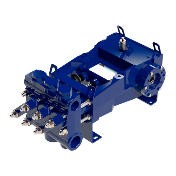
Page 7: Figure 2: L06 – L16 Pump Assembly With No Pinion Shaft (Includes Hd & Hv)
Doc No: OMM50000903 Rev: B Page 7 of 65 Choice of straight keyed shaft or Oil level sight gage allows mounting flange for direct coupling remote monitoring of oil level (splined shaft) of hydraulic motors and condition. (shown). Heavy-duty power ends are machined from a one- piece gray iron casting for long trouble free life. -
Page 8: Storage Instructions
Doc No: OMM50000903 Rev: B Page 8 of 65 Storage Instructions Proper storage of your FMC pump will insure that it is ready for service when needed. Follow the guidelines below that fit the requirements of your application. FMC pumps come from the factory without crankcase oil and are prepared for storage periods of up to six (6) months in proper environmental conditions. -
Page 9: Returning A Stored Pump To Operation
Doc No: OMM50000903 Rev: B Page 9 of 65 Drain the oil from the pump power end. Remove the rear cover to expose the drive components. Spray all internal parts with a rust preservative that is soluble in lubricating oil while rotating the driveshaft several turns by hand to insure complete coverage. -
Page 10: Installation Guidelines
Doc No: OMM50000903 Rev: B Page 10 of 65 Installation Guidelines A proper installation is essential to optimal performance, long service life, and reduced maintenance requirements. Take time to thoroughly plan all aspects of your installation. General Location It is important to position the pump on as flat and level a surface as possible to assist the splash oil lubrication system. -
Page 11: Suction Piping Recommendations
Doc No: OMM50000903 Rev: B Page 11 of 65 the motor. Install the o-ring around the pilot diameter on the mounting face of the motor. Lubricate the o-ring with hydraulic fluid or o-ring lubricant to ease assembly in the mounting flange/bearing housing. Clean the inside of the mounting flange/bearing housing and motor face to remove any dirt or debris. -
Page 12: Discharge Piping Recommendations
Doc No: OMM50000903 Rev: B Page 12 of 65 model are provided on the product data sheets available through FMC or your authorized FMC reseller. FMC does not recommend using the pump in static lift conditions without prior factory approval. Discharge Piping Recommendations 1. -
Page 13: Multiple Pump Systems
Doc No: OMM50000903 Rev: B Page 13 of 65 discharge line or between the pump and relief valve. FMC recommends that the discharge be returned to the tank or drain, not back into the pump suction line. 5. It is recommended that a start-up bypass line and valve be installed to allow flow to bypass the relief valve. -
Page 14: Lubrication Of Power End
Doc No: OMM50000903 Rev: B Page 14 of 65 3. If accessible, check the piston rods to insure that they are free from abrasive particles or debris. Apply a light oil film to the piston rods before start up. 4. Insure that the pressure relief valve and all accessory equipment have been installed and properly adjusted. -
Page 15: Oil Changes
Doc No: OMM50000903 Rev: B Page 15 of 65 Oil Changes Oil changes must be carried out after first 100 hours of operation, and subsequently after every 2500 hours or at least every 12 months. These intervals may be modified depending on actual operating conditions. Oil should be changed when hot to prevent build up of sludge deposits. - Page 16 Doc No: OMM50000903 Rev: B Page 16 of 65 RECOMMENDED LUBRICANT CHART - L06 THROUGH L12 Motor Oil Lubricant Synthetic Lubricant * Type of Ambient Manufacturer Manufacturer Viscosity Viscosity Service Temp Grade Viscosity Brand Name Grade Brand Name (cSt@40 C) (cSt@40 C) Texaco®...
-
Page 17: Inspection And Preventative Maintenance Chart
Doc No: OMM50000903 Rev: B Page 17 of 65 Inspection and Preventative Maintenance Chart Routine maintenance is an essential part of any successful pump installation. Properly maintained FMC pumps are designed to offer years of trouble-free service. Regular maintenance and inspection will keep your pump operating at peak performance. -
Page 18: Estimated Life Of Wearing Components
Doc No: OMM50000903 Rev: B Page 18 of 65 Estimated Life of Wearing Components The information given here is an estimate of the average wear life of listed components in clean liquid service. It is not a guarantee of life for any given application, but is intended to facilitate maintenance schedules and stocking of spares. -
Page 19: Component Parts List
Doc No: OMM50000903 Rev: B Page 19 of 65 Component Parts List A typical pump configuration is shown below for general reference purposes. This will aid in identifying components for service procedures outlined in the following sections. Each size “L” series pump may have a slightly different appearance. The Industrial Pump models have a pinion shaft for internal gear reduction. -
Page 20: Figure 4: Fluid End Components
Doc No: OMM50000903 Rev: B Page 20 of 65 Figure 4: Fluid End Components The illustrations above depict a typical pump with disc valves, and Type A piston cups. Alternate construction “threaded” style valve covers and Type B style pistons may be used on some models. - Page 21 Doc No: OMM50000903 Rev: B Page 21 of 65 Quantities for Each Model Item Component Description L06 & HD L09 HD L11 & HD Power Frame Crankshaft Pinion Shaft Connection Rod Assembly Rod Bearing Wrist Pin Crosshead Assembly Seal Holder Oil Seal, Piston Rod Seal Retainer Nut Gasket, Seal Retainer...
- Page 22 Doc No: OMM50000903 Rev: B Page 22 of 65 Quantities for Each Model Item Component L06 & Description L09 HD L11 & HD Gasket, Power End Valve Cover O-Ring, Valve Cover Clamp, Valve Cover Stud, Valve Cover Hex Nut, Valve Cover Cylinder Cover O-Ring, Cylinder Cover Back Up Ring...
-
Page 23: Service Procedures
Doc No: OMM50000903 Rev: B Page 23 of 65 10.0 Service Procedures FMC pumps are designed to simplify all required maintenance. The following sections illustrate step-by-step instructions for performing most common service procedures of a pump. Read each section before starting service work on the pump. Refer to Figures 3 and 4 for location of components. - Page 24 Doc No: OMM50000903 Rev: B Page 24 of 65 1. It is recommended that a sufficient quantity of clean water be pumped through the fluid end before starting any service procedures that involve fluid end components. This will remove a significant portion of contaminants left in the fluid cylinder by the normal pumpage and improve the ability to work with parts or see potential problems.
- Page 25 Doc No: OMM50000903 Rev: B Page 25 of 65 6. Using a socket wrench with a long extension, remove the hex piston nut (42) from the piston/crosshead rod (7). This nut secures the piston assembly to the piston/crosshead rod. 7. Following the hex piston nut (42) removal, use the FMC piston tool (A5049) to pull the piston assembly from the cylinder (39).
- Page 26 Doc No: OMM50000903 Rev: B Page 26 of 65 10. Inspect all parts for damage or unusual wear. Insure that the interior surface of the cylinder (39) is smooth and free of cracks or grooves. New piston cups (40) will fail prematurely if installed in liners with damaged bores.
-
Page 27: Removing The Fluid Cylinder
Doc No: OMM50000903 Rev: B Page 27 of 65 10.2 Removing the Fluid Cylinder NOTE: The fluid cylinder (37) may be removed to inspect for internal damage, to be repaired, to replace the fluid cylinder, to replace damaged cylinders, cylinder o-rings, or to service piston rod seals. - Page 28 Doc No: OMM50000903 Rev: B Page 28 of 65 7. Always replace the cylinder gaskets (48) when the cylinders have been moved or replaced. 8. Installation will be the reverse of this procedure. 9. Torque all fasteners as outlined in the Fastener Torque Requirements, Section 11.0 of this manual.
-
Page 29: Replacing Valves
Doc No: OMM50000903 Rev: B Page 29 of 65 10.3 Replacing Valves 1. Three types of valves may be supplied with various models of the “L” series pumps. They are disc type valves, AR style valves, and ball type valves. The next steps must be performed for each type of valve. - Page 30 Doc No: OMM50000903 Rev: B Page 30 of 65 6. For AR valves refer to section 10.3.1. This document describes the methods for removing and installing the AR valves. 7. For disc valves refer to section 10.3.2. This document describes the methods for removing and installing disc valves.
-
Page 31: Replacing Ar Valves
Doc No: OMM50000903 Rev: B Page 31 of 65 10.3.1 Replacing AR Valves 10.3.1.1 Introduction The AR, Abrasion Resistant, valve is a durable wing-guided, spring-loaded check valve. It is used with abrasive fluids, bentonite mud, water, oil etc., and provides excellent performance and long service life. -
Page 32: Knock Out Tool
Doc No: OMM50000903 Rev: B Page 32 of 65 10.3.1.2 Knock Out Tool The simplest of the tools is the removal and installation tool, part number P504436. It is used primarily on the M06 and L06 model pumps for small valves. To remove a valve, this tool is inserted from the bottom of the fluid cylinder and is stopped by the bottom of the valve seat. -
Page 33: Picture 1: Removing The Valve From The Seat
Doc No: OMM50000903 Rev: B Page 33 of 65 Picture 1: Removing the valve from the seat Picture 2: Removing the valve from the fluid cylinder Subject to contractual terms and conditions to the contrary, this document and all the information contained herein are the confidential and exclusive property of FMC Technologies, and may not be reproduced, disclosed, or made public in any manner prior to express written authorization by FMC. -
Page 34: Eccentric Discs
Doc No: OMM50000903 Rev: B Page 34 of 65 10.3.1.3 Eccentric Discs The second style of tool is more complex but capable of exerting more force on the valve than the Knock Out Tool. This style can be used on all sizes of the AR valves in all of the pump models. -
Page 35: Figure 8: Eccentric Disc In Use
Doc No: OMM50000903 Rev: B Page 35 of 65 This style of tool includes a disc that passes through the seat to allow force to be placed underneath it. The disc has a threaded hole that is at the center of the disc (concentric disc). -
Page 36: Figure 9: Removing The Seat
Doc No: OMM50000903 Rev: B Page 36 of 65 Nut Stop Bumper Tension nut Strong Back Tension Rod Valve Seat with cage, spring and valve body removed Eccentric Discs Figure 9: Removing the seat Subject to contractual terms and conditions to the contrary, this document and all the information contained herein are the confidential and exclusive property of FMC Technologies, and may not be reproduced, disclosed, or made public in any manner prior to express written authorization by FMC. -
Page 37: Figure 10: Hydraulic Power Used To Remove Valve Seat
Doc No: OMM50000903 Rev: B Page 37 of 65 A variation of this is the use of a hydraulic pump and cylinder jack (porta power) to generate the load that the bumper, strong back, and nut would generate. This is shown if Figure 8. -
Page 38: Mandrel Type
Doc No: OMM50000903 Rev: B Page 38 of 65 10.3.1.4 Mandrel Type This is a variation of the Eccentric Disc type. It can be used on all sizes of valves. It has a more uniform loading of the seat than the Eccentric Disc type and therefore more pulling capacity. -
Page 39: Figure 11: Mandrel Tool In Use
Doc No: OMM50000903 Rev: B Page 39 of 65 Threads on the inside diameter to connect to the tension member Threaded Mandrel O-Rings Valve Seat, Fluid Cylinder not shown Expanding Collets Figure 11: Mandrel Tool in use The lower part of the mandrel and the collets are passed through the valve seat and then slid down the mandrel to expand them. -
Page 40: Threaded Type (Ar Valves Only)
Doc No: OMM50000903 Rev: B Page 40 of 65 10.3.1.5 Threaded Type (AR Valves Only) The threaded type can only be used on valves that have the through bore of the seat threaded prior to installation. The load capacity is similar to the Mandrel Type but it is simpler to use. -
Page 41: Installation Of Ar Valves
Doc No: OMM50000903 Rev: B Page 41 of 65 10.3.1.6 Installation of AR Valves AR valves are installed differently depending on their size. Larger valves are assembled at the factory with the cage screwed on hand-tight before shipping while smaller valves are tightened with a torque wrench to final specifications. Follow the instructions in section 10.3.1.6.1 for all series 3 and 23 valves as well as valve part numbers 3267652 and P533637. -
Page 42: Installing Larger, Non-Factory Torqued Ar Valves
Doc No: OMM50000903 Rev: B Page 42 of 65 10.3.1.6.2 Installing Larger, Non-Factory Torqued AR Valves The suction valve must be installed before the discharge valves. The following reassembly procedure is applicable for both. 1. Select a new valve seat. Disassembly of a new valve assembly may be necessary. -
Page 43: Replacing "L" Series Disc Type Valves
Doc No: OMM50000903 Rev: B Page 43 of 65 10.3.2 Replacing “L” Series Disc Type Valves 10.3.2.1 Introduction The disc type valve used in “L” series FMC pump models is shown in Figure 13. The standard construction of stainless steel seat, disc, and stop are a cost effective design with excellent performance and ample life. -
Page 44: Valve Removal Tools
Doc No: OMM50000903 Rev: B Page 44 of 65 10.3.2.2 Valve Removal Tools There are three (3) Knock Out tools available for removing valves from “L” series pumps. The P534695 Small Ball Knock Out tool is the preferred tool for the smaller valves in the L06 and L09 pumps. -
Page 45: Installation Of Disc Valves
Doc No: OMM50000903 Rev: B Page 45 of 65 10.3.2.3 Installation of Disc Valves The suction valves must be installed before the discharge valves can be installed. The following reassembly procedure is applicable for both. 1. Select a new valve assembly and check to insure the taper on the valve is clean. 2. -
Page 46: Servicing The Power End
Doc No: OMM50000903 Rev: B Page 46 of 65 10.4 Servicing the Power End 10.4.1 Replacing Piston Rod Oil Seals NOTE: Insure that all pressure inside the pump fluid cylinder has been bled off before starting any service work. CAUTION: CHECK TO INSURE THAT THE POWER IS LOCKED OUT AND TAGGED OUT. -
Page 47: Subject To Contractual Terms And Conditions To The Contrary, This Document And All The Information Contained Herein Are The Confidential And Exclusive
Doc No: OMM50000903 Rev: B Page 47 of 65 5. To rebuild, insert new seals (9) in the seal holder (8), taking care to insure they are oriented in the same manner as the ones that were removed. Do not reuse seals that have been removed from the pump. -
Page 48: Replacing Power End Bearings & Crankshaft
Doc No: OMM50000903 Rev: B Page 48 of 65 10.4.2 Replacing Power End Bearings & Crankshaft Disconnect the driver from the pump and insure that suction and WARNING: discharge lines are disconnected or blocked and have no pressure applied. 1. Removal of the fluid cylinder simplifies crankshaft removal on L16 pump models. 2. -
Page 49: Subject To Contractual Terms And Conditions To The Contrary, This Document And All The Information Contained Herein Are The Confidential And Exclusive
Doc No: OMM50000903 Rev: B Page 49 of 65 6. NOTE: Connecting rods and caps are matched sets and must always be reassembled with their original mate and in the same orientation. Note the numbered codes stamped on each half of the connecting rod assemblies and make certain they are installed as matched set and in the same orientation when re-assembling the... -
Page 50: Subject To Contractual Terms And Conditions To The Contrary, This Document And All The Information Contained Herein Are The Confidential And Exclusive
Doc No: OMM50000903 Rev: B Page 50 of 65 12. Remove the hex head cap screws (28), bearing housings (12 and 36), and shims (13) from both sides of the pump. Count and record the shims on each side to facilitate assembly. The gaskets (14) may adhere to the power frame surface and can be left in place if they are not damaged. -
Page 51: Subject To Contractual Terms And Conditions To The Contrary, This Document And All The Information Contained Herein Are The Confidential And Exclusive
Doc No: OMM50000903 Rev: B Page 51 of 65 15. Bearing cones (22) may be removed from the crankshaft using an automotive type bearing puller. Bearing cups (23) can be removed from the bearing housing using a puller if a sufficient lip is available for the puller arms to grab. -
Page 52: Subject To Contractual Terms And Conditions To The Contrary, This Document And All The Information Contained Herein Are The Confidential And Exclusive
Doc No: OMM50000903 Rev: B Page 52 of 65 22. To replace the tapered roller bearings on the crankshaft, heat the cones to a maximum of 300 F (149 C). Slide them down the shaft unit they are full seated against shoulder. -
Page 53: Subject To Contractual Terms And Conditions To The Contrary, This Document And All The Information Contained Herein Are The Confidential And Exclusive
Doc No: OMM50000903 Rev: B Page 53 of 65 31. Move the crankshaft to one side of the power frame using a light tap from a rubber mallet or a pry bar. Rotate the crankshaft several turns and repeat the light taps from a rubber mallet or the use of a pry bar to insure the crankshaft is to one side. -
Page 54: Fastener Torque Requirements
Doc No: OMM50000903 Rev: B Page 54 of 65 11.0 Fastener Torque Requirements NOTICE: No pump service procedure is complete without insuring that the fasteners have been properly torqued. Failure to properly tighten the pump bolts could cause the pump to leak or possibly allow the pump to fail. Always use a calibrated torque wrench during the installation of all critical fasteners listed in Table 4 below. -
Page 55: Critical Clearances
Doc No: OMM50000903 Rev: B Page 55 of 65 SIZE 0.500 0.625 0.750 0.875 1.000 1.125 1.250 Ft-lb (N-m) Table 5: Torque Values for Xylan-Coated Fasteners 12.0 Critical Clearances When maintenance requiring disassembly of the power end is performed, the following clearances should be checked to see if they are within factory specification or within maximum allowable limits. -
Page 56: Valve Removal And Installation Tools
Doc No: OMM50000903 Rev: B Page 56 of 65 13.0 Valve Removal and Installation Tools Table 7 shows the FMC part numbers for valve removal tools for the various AR valves used in the models specified. Table 8 on the following page shows the FMC part numbers for valve removal and installation tools for the various Disc valves used. -
Page 57: Subject To Contractual Terms And Conditions To The Contrary, This Document And All The Information Contained Herein Are The Confidential And Exclusive
Doc No: OMM50000903 Rev: B Page 57 of 65 L06 SIZE PUMPS INSTALLATION TOOL VALVE TYPE VALVE ASSY VALVE SIZE REMOVAL TOOL Disc 5257290 1.312 G.L. / .94 ID P534695 (Small Ball) P534699 Disc 5257291 1.437 G.L. / .94 ID P534695 (Small Ball) P534702 Disc... -
Page 58: Trouble-Shooting Pumps
Doc No: OMM50000903 Rev: B Page 58 of 65 14.0 Trouble-Shooting Pumps This chart is designed to aid in the solution of pump and pump system problems. Once the problem has been identified, work through the possible causes and solutions until the problem has been corrected. -
Page 59: Subject To Contractual Terms And Conditions To The Contrary, This Document And All The Information Contained Herein Are The Confidential And Exclusive
Doc No: OMM50000903 Rev: B Page 59 of 65 Pump runs -Broken or weak valve spring -Replace valve spring rough, -Valve damaged or unseated -Repair/replace valve or re-seat knocks, or -Loose plunger, piston, or rod -Tighten loose components vibrates -Low oil level in power end -Fill to proper level (ONLY) -Excessive connecting rod bearing... -
Page 60: Subject To Contractual Terms And Conditions To The Contrary, This Document And All The Information Contained Herein Are The Confidential And Exclusive
Doc No: OMM50000903 Rev: B Page 60 of 65 Fluid leaking -Piston cups are worn -Replace piston cup from pump -Piston to rod o-ring damaged -Replace o-ring -Fluid cylinder bolts not properly tightened -Properly tighten and torque bolts -Fluid cylinder o-rings (or gaskets) damaged -Replace damaged o-rings or gaskets Reduced -Highly abrasive particles in fluid... -
Page 61: Ordering Parts
Doc No: OMM50000903 Rev: B Page 61 of 65 15.0 Ordering Parts Service parts are available through FMC’s worldwide network of distributors or from the original supplier for the equipment that the pump is a component of. If unsure where to purchase parts, contact FMC customer service for the location of an authorized parts retailer in your area. -
Page 62: Glossary Of Commonly Used Terms
Doc No: OMM50000903 Rev: B Page 62 of 65 16.0 Glossary of Commonly Used Terms CAPACITY The total volume throughput per unit of time at suction conditions. It includes both liquid and any dissolved or entrained gases. For all practical purposes this can be considered the volume flow rate in the suction pipe. -
Page 63: Subject To Contractual Terms And Conditions To The Contrary, This Document And All The Information Contained Herein Are The Confidential And Exclusive
Doc No: OMM50000903 Rev: B Page 63 of 65 FLOODED SUCTION Implies that the level of liquid in the suction vessel is above the centerline of the suction port of the pump. FLUID END The portion of the pump that converts the linear motion supplied by the power end into fluid flow at pressure. -
Page 64: Subject To Contractual Terms And Conditions To The Contrary, This Document And All The Information Contained Herein Are The Confidential And Exclusive
Doc No: OMM50000903 Rev: B Page 64 of 65 STROKE LENGTH The length of one complete, unidirectional motion of the piston or plunger. Stroke length is usually expressed in inches. PUMP VALVE A check valve that allows flow of liquid in one direction. -
Page 65: Doc No: Omm50000903 Rev: B
Doc No: OMM50000903 Rev: B Page 65 of 65 17.0 Reference Information Use the following section to record key information about your specific pump model. Information such as part and serial numbers will be needed when ordering service parts. This data may be found stamped on the metal nameplate located on the pump power frame.
Need help?
Do you have a question about the FMC L06 and is the answer not in the manual?
Questions and answers