Table of Contents
Advertisement
Quick Links
Instruction Manual
Form 1292
July 2007
Type 655 and 655R Actuators
for Self-Operated Control
Contents
. . . . . . . . . . . . . . . . . . . . . . . . . . . . . . .
. . . . . . . . . . . . . . . . . . . . . . . . .
. . . . . . . . . . . . . . . . . . . . . . . . . . . . . .
. . . . . . . . . . . . . . . . . . . . . . . . . . . .
. . . . . . . . . . . . . . . . . . . . . . . . . . . . . . . .
. . . . . . . . . . . . . . . . . . . . . . . .
. . . . . . . . . . . . . . . . . . . . . . . . . . . . . . . . . . .
. . . . . . . . . . . . . . . . . . . . . . . . . . . . . . . . .
. . . . . . . . . . . . . . . . . . . . . . . . . . . . . .
. . . . . . . . . . . . . . . . . . . . . . . . . . . . . . . . .
. . . . . . . . . . . . . . . . . . . . . . . . . . . .
. . . . . . . . . . . . . . . . . . . . . . . . . . . . . . . .
Introduction
Scope of Manual
This instruction manual provides installation,
adjustment, maintenance, and parts ordering for the
Type 655 and 655R actuators and the top-mounted
handwheel. Refer to separate instruction manuals
for information about valves and accessories used
with these actuators.
Do not install, operate, or maintain 655 and 655R
actuators without first D being fully trained and
qualified in valve, actuator, and accessory
installation, operation, and maintenance, and
D carefully reading and understanding the contents
of this manual. If you have any questions about
these instructions, contact your Emerson Process
Managementt sales office before proceeding.
Description
Type 655 and 655R actuators (figure 1) are
pressure-actuated, spring-and-diaphragm actuators
used in conjunction with various valves to provide
www.Fisher.com
. . . . . . . . . . . . . . . . . . . . . .
. . . . . .
. . . . . . . . .
. . . . . . . . . . . . . . . . .
. . . . . . . . . . . . . . . . .
10
12
12
655 and 655R Actuators
1
1
1
2
2
3
6
6
6
7
7
7
7
8
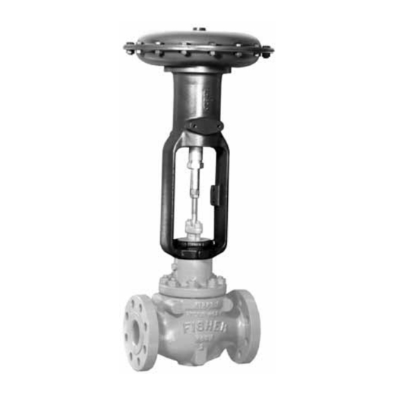
W0466-1 / IL
Figure 1. Type 655-ED Pressure-Reducing Valve
control for a wide variety of pressure regulation
applications. Type 655 actuators are used for
pressure-reducing service when mounted on
push-down-to-close valves such as the Design ED
and ET valves. Type 655R actuators are used for
pressure-relief service when mounted on
push-down-to-open valves such as the Design EDR
and ETR valves. Both types are self-operated and
direct-acting; that is, increasing pressure in the
diaphragm casing forces the actuator stem
downward, and decreasing the pressure allows the
actuator spring to lift the actuator stem upward.
Neither Emerson, Emerson Process
Management, nor any of their affiliated
entities assumes responsibility for the
selection, use and maintenance of any
product. Responsibility for the
selection, use, and maintenance of any
product remains with the purchaser
and end-user.
Note
Advertisement
Table of Contents

Related Manuals for Emerson Fisher 655R


Summary of Contents for Emerson Fisher 655R
-
Page 1: Table Of Contents
D carefully reading and understanding the contents Note of this manual. If you have any questions about Neither Emerson, Emerson Process these instructions, contact your Emerson Process Management, nor any of their affiliated Managementt sales office before proceeding. entities assumes responsibility for the... -
Page 2: Specifications
35, 45 36, 46 –29 to 82_C (–20 to 180_F) with standard diaphragm material. For the fluid and temperature capabilities of nonstandard diaphragm materials, consult your Emerson Process Management Actuator Pressure Setting Ranges sales office See table 2 Casing Pressure Connections... -
Page 3: Actuator Mounting
Instruction Manual Form 1292 655 and 655R Actuators July 2007 plate (key 4) against the upper diaphragm casing CAUTION (key 1). 2. Perform the following steps as appropriate for To avoid premature wear of the either push-down-to-close or push-down-to-open diaphragm due to debris in the valve action. - Page 4 Instruction Manual Form 1292 655 and 655R Actuators July 2007 Table 2. Actuator Pressure-Setting Ranges PRESSURE PRESSURE PRESSURE PRESSURE ACTUA- ACTUA- REDUCTION RELIEF REDUCTION RELIEF SPRING PART SPRING PART SPRING PART SPRING PART Minimum Maximum Minimum Maximum Minimum Maximum Minimum Maximum NUMBER NUMBER NUMBER...
- Page 5 Instruction Manual Form 1292 655 and 655R Actuators July 2007 Table 3. Effective Diaphragm Area TRAVEL DOWN FROM UPPER CASING STOP, mm (IN.) ACTUA- ACTUA- 3 (0.125) 5 (0.1875) 6 (0.25) 10 (0.375) 11 (0.4375) 13 (0.5) 14 (0.5625) 19 (0.75) 22 (0.875) SIZE 3A, 4A...
-
Page 6: Loading Connections
Instruction Manual Form 1292 655 and 655R Actuators July 2007 f. Stroke the actuator, and measure the stem Note movement to check travel. If the movement is Changing the spring adjustment will more than full travel, turn the valve stem out of not change the actuator pressure the actuator stem the amount of over-travel. -
Page 7: Startup For Pressure-Relief Service
Instruction Manual Form 1292 655 and 655R Actuators July 2007 4. Slowly open the upstream shutoff valve. Shutdown For both pressure-reducing and pressure-relief applications, refer to figure 2, and follow the Startup For Pressure-Relief Service procedures described below. 1. Open the needle valve in the control line. 1. -
Page 8: Actuator
Instruction Manual Form 1292 655 and 655R Actuators July 2007 pressurized, even when the valve has following procedure, make sure the been removed from the pipeline. adjusting screw (key 10) remains Process fluids may spray out under screwed into the yoke (key 7). pressure when removing the packing a. - Page 9 Instruction Manual Form 1292 655 and 655R Actuators July 2007 diaphragm casing (key 5). Some Type 655R Note actuators will have travel stops (key 13, not shown) When you replace actuator in place of three of these six cap screws. diaphragms in the field, take care to 9.
-
Page 10: Top-Mounted Handwheel
Instruction Manual Form 1292 655 and 655R Actuators July 2007 16. To start up and adjust the actuator, follow the 5. Turn the handwheel clockwise two or three turns. procedures outlined in the Startup section of this Remove the hex nut (key 22, figures 5 and 6; instruction manual. - Page 11 Instruction Manual Form 1292 655 and 655R Actuators July 2007 tightened to the proper load to prevent ensure the diaphragm casing bolts are leakage, but not crush the material. tightened to the proper load to prevent Perform the following tightening leakage, but not crush the material.
-
Page 12: Parts Ordering
Form 1292 655 and 655R Actuators July 2007 Parts Ordering Parts List When corresponding with your Emerson Process Note Management sales office about this equipment, refer to the serial number found on the actuator Part numbers are shown for recommended spares nameplate (key 17, figure 4). - Page 13 Instruction Manual Form 1292 655 and 655R Actuators July 2007 APPLY LUB PART NOT SHOWN : 31 28A1216-C/DOC Figure 5. Size 3A and 4A Top-Mounted Handwheel Assembly Description Part Number Drive Screw 30A8341-A/DOC Cap Screw APPLY MOLY-GREASE LUBRICANT TO ADJUSTING SCREW Hex Nut Cap Screw Top-Mounted Handwheel...
- Page 14 Instruction Manual Form 1292 655 and 655R Actuators July 2007 BV8008-E/DOC Figure 7. Size 32 through 46 Top-Mounted Handwheel Assembly. APPLY LUB PARTS NOT SHOWN : 30 & 31 38A1217-B/DOC Figure 6. Size 3B and 4B Top-Mounted Handwheel Assembly Key 6 Spring, steel SPRING RATE SAFE LOAD COLOR CODE...
- Page 15 Instruction Manual Form 1292 655 and 655R Actuators July 2007...
- Page 16 July 2007 Fisher is a mark owned by Fisher Controls International LLC, a member of the Emerson Process Management business division of Emerson Electric Co. Emerson Process Management, Emerson, and the Emerson logo are trademarks and service marks of Emerson Electric Co.
Need help?
Do you have a question about the Fisher 655R and is the answer not in the manual?
Questions and answers