Table of Contents
Advertisement
Quick Links
Advertisement
Table of Contents

Related Manuals for Asus RS700-E6 ERS4


Summary of Contents for Asus RS700-E6 ERS4
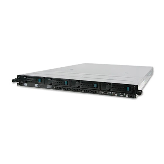
- Page 1 RS700-E6/RS4 1U Rackmount Server User Guide...
- Page 2 ASUSTeK COMPUTER INC. (“ASUS”). ASUS provides this manual “as is” without warranty of any kind, either express or implied, including but not limited to the implied warranties or conditions of merchantability or fitness for a particular purpose. In no...
-
Page 3: Table Of Contents
Expansion slot ................2-9 2.4.1 Installing an expansion card to the riser card bracket ..2-9 2.4.2 Installing ASUS PIKE RAID card (optional) ....2-10 2.4.3 Configuring an expansion card ........2-11 Installing ASUS Server Management Board (optional)... 2-12 Installing additional power supply unit ........2-13... -
Page 4: Contents
Chapter 5: BIOS setup Managing and updating your BIOS ..........5-2 5.1.1 AFUDOS utility ..............5-2 5.1.2 ASUS CrashFree BIOS 3 utility ........5-4 BIOS setup program ..............5-5 5.2.1 BIOS menu screen ............5-6 5.2.2 Menu bar ................. 5-6 5.2.3... - Page 5 Contents 5.4.8 Hardware Monitor ............5-25 5.4.9 ACPI Configuration ............5-26 Server menu ................5-28 5.5.1 IPMI Configuration ............5-28 5.5.2 Remote Access Configuration ........5-29 Boot menu .................. 5-31 5.6.1 Boot Device Priority ............5-31 5.6.2 Boot Settings Configuration .......... 5-32 5.6.3 Security .................
- Page 6 Contents Chapter 7: Driver installation RAID driver installation ............... 7-2 7.1.1 Creating a RAID driver disk ..........7-2 7.1.2 Installing the RAID controller driver ........ 7-5 Intel chipset device installation ..........7-12 ® LAN driver installation ............... 7-14 VGA driver installation............... 7-17 Management applications and utilities installation ....
-
Page 7: Notices
Notices Federal Communications Commission Statement This device complies with Part 15 of the FCC Rules. Operation is subject to the following two conditions: • This device may not cause harmful interference, and • This device must accept any interference received including interference that may cause undesired operation. -
Page 8: Safety Information
Safety information Electrical Safety • Before installing or removing signal cables, ensure that the power cables for the system unit and all attached devices are unplugged. • To prevent electrical shock hazard, disconnect the power cable from the electrical outlet before relocating the system. •... -
Page 9: About This Guide
About this guide Audience This user guide is intended for system integrators, and experienced users with at least basic knowledge of configuring a server. Contents This guide contains the following parts: Chapter 1: Product Introduction This chapter describes the general features of the server, including sections on front panel and rear panel specifications. - Page 10 Refer to the following sources for additional information, and for product and software updates. ASUS Server Web-based Management (ASWM) user guide This manual tells how to set up and use the proprietary ASUS server management utility. ASUS websites The ASUS websites worldwide provide updated information for all ASUS...
- Page 11 Chapter 1 This chapter describes the general features of the server, including sections on front panel and rear panel specifications. ASUS RS700-E6/RS4...
-
Page 12: Chapter 1: Product Introduction
If any of the above items is damaged or missing, contact your retailer. Serial number label Before requesting support from the ASUS Technical Support team, you must take note of the product’s serial number containing 12 characters such as xxxxxxxxxxxx. -
Page 13: System Specifications
1.3 System specifications The ASUS RS700-E6/RS4 is a 1U barebone server system featuring the ASUS Z8PS-D12-1U server board. The server supports Intel ® LGA1366 Xeon ® 5500 series processors, plus other latest technologies through the chipsets onboard. Model Name RS700-E6/RS4 2 x Socket LGA1366... - Page 14 Remote Optional ASMB4-iKVM for KVM-over-IP support Management Hardware Solution Software ASUS ASWM 2.0 Dimension (HH x WW x DD) 687.8mm x 444mm x 43.4mm Net Weight Kg (CPU, DRAM & 15 Kg HDD not includeed) 770W (80+) 1+1 Redundant Power Supply (Default...
-
Page 15: Front Panel Features
The middle part includes the I/O shield with openings for the rear panel connectors on the motherboard. The ports for the PS/2 keyboard, PS/2 mouse, USB, VGA, and Gigabit LAN do not appear on the rear panel if motherboard is not present. ASUS RS700-E6/RS4... -
Page 16: Internal Features
The barebone server does not include a floppy disk drive. Connect a USB floppy disk drive to any of the USB ports on the front or rear panel if you need to use a floppy disk. • Only ASUS CD/DVD-ROMs fit the optical drive bay. Chapter 1: Product introduction... -
Page 17: Led Information
LAN connection is present 1.7.2 LAN (RJ-45) LEDs SPEED LED ACT/LINK LED ACT/LINK LED SPEED LED Status Description Status Description No link 10 Mbps connection GREEN Linked ORANGE 100 Mbps connection BLINKING Data activity GREEN 1 Gbps connection ASUS RS700-E6/RS4... -
Page 18: Hdd Status Led
1.7.3 HDD status LED HDD Status LED HDD Activity LED SATAII/SAS HDD LED Description GREEN ON SATAII/SAS HDD power ON SATAII/SAS HDD not present HDD Status LED 1. HDD has failed and should be swapped Blinking immediately (slow blinking, 2 times/sec) 2. - Page 19 Chapter 2 This chapter lists the hardware setup procedures that you have to perform when installing or removing system components. ASUS RS700-E6/RS4...
-
Page 20: Chapter 2: Hardware Setup
ASUS will shoulder the cost of repair only if the damage is shipment/transit-related. • Keep the cap after installing the motherboard. ASUS will process Return Merchandise Authorization (RMA) requests only if the motherboard comes with the cap on the LGA1366 socket. - Page 21 Lift the load lever in the direction of the arrow to a 135º angle. Load plate Lift the load plate with your thumb and forefinger to a 100º angle. Remove the PnP cap from the CPU socket. PnP cap ASUS RS700-E6/RS4...
- Page 22 Position the CPU over the socket, making sure that the gold triangle is on the bottom-left corner of the socket, and then fit the socket alignment key into the CPU notch. Gold triangle The CPU fits in only one correct mark orientation.
-
Page 23: Installing The Cpu Heatsink
CPU. Turn up the bridge board cover near the system fan. Position the airduct on top of the heatsink and carefully lower it until it fits in place. Recover the bridge board cover. Bridge board cover ASUS RS700-E6/RS4... -
Page 24: System Memory
System memory 2.2.1 Overview The motherboard comes with twelve (12) Double Data Rate 3 (DDR3) Dual Inline Memory Modules (DIMM) sockets. The figure illustrates the location of the DDR3 DIMM sockets: DIMM_A2 DIMM_A1 DIMM_B2 DIMM_B1 DIMM_C2 DIMM_C1 DIMM_D2 DIMM_D1 DIMM_E2 DIMM_E1 DIMM_F2 DIMM_F1... - Page 25 Always install DIMMs with the same CAS latency. For optimum compatibility, we recommend that you obtain memory modules from the same vendor. Refer to the Qualified Vendors List on the ASUS web site. • You may install varying memory sizes in Channel A, Channel B and Channel C.
-
Page 26: Hard Disk Drives
Hard disk drives The system supports four hot-swap SATAII/SAS hard disk drives. The hard disk drive installed on the drive tray connects to the motherboard SATAII/SAS ports via the SATAII/SAS backplane. Follow the illustration below for HDD installation. To install a hot-swap SATAII/SAS HDD Release a drive tray by pushing the spring lock to the right, and then pulling the tray lever outward. -
Page 27: Expansion Slot
Align the riser card bracket with the cards to the PCI Express slot on the motherboard. Press the riser card bracket until the golden connectors completely fit the slot and the bracket aligns with the rear panel. Connect the cable(s) to the card, if applicable. ASUS RS700-E6/RS4... -
Page 28: Installing Asus Pike Raid Card (Optional)
2.4.2 Installing ASUS PIKE RAID card (optional) Follow the steps below to install an optional ASUS RAID card on your motherboard. Locate the PIKE RAID card slot on the motherboard. Turn up the bridge board cover near the system fan. -
Page 29: Configuring An Expansion Card
ACPI Mode when used IRQ Holder for PCI Steering IRQ Holder for PCI Steering PS/2 Compatible Mouse Port Numeric Data Processor Primary IDE Channel Secondary IDE Channel * These IRQs are usually available for ISA or PCI devices. ASUS RS700-E6/RS4 2-11... -
Page 30: Installing Asus Server Management Board (Optional)
Installing ASUS Server Management Board (optional) ASUS Server Management Board is an Intelligent Platform Management Interface (IPMI) 2.0-compliant board that allows users to monitor, control and manage a remote server from the local or central server in local area network (LAN). -
Page 31: Installing Additional Power Supply Unit
Installing additional power supply unit ASUS RS700-E6 comes with one 770W power supply unit. You can install an additional power supply unit to form a 1+1 redundant power supply module for eliminating system and application downtime by redundancy power backup. - Page 32 2-14 Chapter 2: Hardware setup...
- Page 33 Chapter 3 This chapter describes how to install the optional components and devices into the barebone server. ASUS RS700-E6/RS4...
-
Page 34: Chapter 3: Installation Options
Rack rails assembly If you have the rackmount rail kit, it contains two pairs of rails (one pair for each side of the barebone system). Follow the illustrations below for rackmount rail kit assembly. Rear left inner rail Rear right inner rail Left outer rail Right outer rail... - Page 35 Ensure that it is level with the previously installed rack rail. Align the inner rails on the server with the outer rails on the rack. Push the server all the way into the rack. 10. Secure the server to the rack. ASUS RS700-E6/RS4...
-
Page 36: Removing The Server From The Rack
Removing the Server from the rack Follow the illustrations below to remove the server from the rack. Release the rack screws and pull out the server from the rack. Push the front latches on the two sides to release the front inner rails. Push the rear latches on the two sides to release the rear inner rails. - Page 37 Chapter 4 This chapter includes the motherboard layout and brief descriptions of the jumpers and internal connectors. ASUS RS700-E6/RS4...
-
Page 38: Chapter 4: Motherboard Info
Motherboard layout Chapter 4: Motherboard information... - Page 39 Serial port connector (10-1 pin COM2) LPC debug card connector (14-1 pin LPC1) 4-10 Baseboard Management Controller (BMC) connector 4-10 (14-pin BMC_FW1) Internal LEDs Page Standby power LED 4-11 Baseboard Management Controller LED (BMC_LED1) 4-11 Diagnose LEDs 4-12 ASUS RS700-E6/RS4...
-
Page 40: Jumpers
Jumpers Clear RTC RAM (CLRTC1) This jumper allows you to clear the Real Time Clock (RTC) RAM in CMOS. You can clear the CMOS memory of date, time, and system setup parameters by erasing the CMOS RTC RAM data. The onboard button cell battery powers the RAM data in CMOS, which include system setup information such as system passwords. - Page 41 1–2 to activate the VGA feature. LAN controller setting (3-pin LAN_SW1, LAN_SW2) These jumpers allow you to enable or disable the onboard Intel 82574L ® Gigabit LAN1/2 controller. Set to pins 1–2 to activate the Gigabit LAN feature. ASUS RS700-E6/RS4...
- Page 42 Force BIOS recovery setting (3-pin RECOVERY1) This jumper allows you to quickly update or recover the BIOS settings when it becomes corrupted. To update the BIOS: Prepare a USB flash drive that contains the original or latest BIOS for the motherboard (XXXXXX.ROM) and the AFUDOS.EXE utility. Set the jumper to pins 2–3.
- Page 43 • LSI Mega RAID 5 fucntion is available only when you place the iBTN to I_BTN1 slot and install an optional ASUS PIKE RAID card. RAID configuration utility selection (3-pin RAID_SEL1) This jumper allows you to select the RAID configuration utility to use when you create disk arrays.
- Page 44 DDR3 voltage setting (4-pin LVDDR3_SEL1/2) These jumpers allow you to select DDR3 DIMM voltage settings. Place the jumper caps on pins 1–2 if you want to control DDR3 voltage by BIOS settings (default). Place the jumper caps on pins 2–3 to force the DDR3 DIMMs to run at +1.2V.
-
Page 45: Internal Connectors
This connector is for a serial (COM) port. Connect the serial port module cable to this connector, then install the module to a slot opening at the back of the system chassis. The serial port module is purchased separately. ASUS RS700-E6/RS4... - Page 46 LPC debug card connector (14-1 pin LPC1) This connector is for a LPC debug card. The LPC debug card is purchased separately. Baseboard Management Controller (BMC) connector (14-pin BMC_FW1) This is an interface used to plug in an ASMB4-SOL or ASMB4-iKVM management device.
-
Page 47: Internal Leds
The illustration below shows the location of the onboard LED. Baseboard Management Controller LED (BMC_LED1) The BMC LED works with the ASUS ASMB4 management device and indicates its initiation status. When the PSU is plugged and the system is OFF, ASUS ASMB4 management device starts system initiation for about one (1) minute. - Page 48 Diagnose LEDs These red LEDs check key components in sequence during motherboard booting process. If an error is found, the LED next to the error device will continue lighting until the problem is solved. 4-12 Chapter 4: Motherboard information...
- Page 49 Chapter 5 This chapter tells how to change the system settings through the BIOS Setup menus. Detailed descriptions of the BIOS parameters are also provided. ASUS RS700-E6/RS4...
-
Page 50: Chapter 5: Bios Setup
AFUDOS utility (Updates the BIOS in DOS mode using a bootable USB flash drive.) ASUS CrashFree BIOS 3 (To recover the BIOS using a USB flash drive when the BIOS file fails or gets corrupted.) Refer to the corresponding sections for details on these utilities. - Page 51 Updating the BIOS file To update the BIOS file using the AFUDOS utility: Visit the ASUS website (www.asus.com) and download the latest BIOS file for the motherboard. Save the BIOS file to a bootable USB flash drive. Write the BIOS filename on a piece of paper. You need to type the exact BIOS filename at the DOS prompt.
-
Page 52: Asus Crashfree Bios 3 Utility
5.1.2 ASUS CrashFree BIOS 3 utility The ASUS CrashFree BIOS 3 is an auto recovery tool that allows you to restore the BIOS file when it fails or gets corrupted during the updating process. You can update a corrupted BIOS file using a USB flash drive that contains the updated BIOS file. -
Page 53: Bios Setup Program
The BIOS setup screens shown in this section are for reference purposes only, and may not exactly match what you see on your screen. • Visit the ASUS website (www.asus.com) to download the latest BIOS file for this motherboard. ASUS RS700-E6/RS4... -
Page 54: Bios Menu Screen
5.2.1 BIOS menu screen Menu items Menu bar Configuration fields General help BIOS SETUP UTILITY Main Advanced Server Boot Exit Use [ENTER], [TAB] System Time [13:44:30] or [SHIFT-TAB] to System Date [Tue, 10/11/2007] select a field. Use [+] or [-] to SATA 1 [Not Detected] configure system Date. -
Page 55: Menu Items
Down arrow keys or <Page Up> /<Page Pop-up window Down> keys to display the other items on the screen. 5.2.9 General help At the top right corner of the menu screen is a brief description of the selected item. ASUS RS700-E6/RS4... -
Page 56: Main Menu
Main menu When you enter the BIOS Setup program, the Main menu screen appears, giving you an overview of the basic system information. Refer to section 5.2.1 BIOS menu screen for information on the menu screen items and how to navigate through them. BIOS SETUP UTILITY Main Advanced... - Page 57 [MWDMA1] [MWDMA2] [UDMA0] [UDMA1] [UDMA2] [UDMA3] [UDMA4] [UDMA5] [UDMA6] SMART Monitoring [Auto] Sets the Smart Monitoring, Analysis, and Reporting Technology. Configuration options: [Auto] [Disabled] [Enabled] 32Bit Data Transfer [Enabled] Enables or disables 32-bit data transfer. Configuration options: [Disabled] [Enabled] ASUS RS700-E6/RS4...
-
Page 58: Ide Configuration
5.3.4 IDE Configuration The items in this menu allow you to set or change the configurations for the IDE devices installed in the system. Select an item then press <Enter> if you wish to configure the item. BIOS SETUP UTILITY Main IDE Configuration Options SATA Configuration... -
Page 59: Ahci Configuration
SATA Port0 [Auto] Allows you to select the type of device connected to the system. Configuration options: [Auto] [Not Installed] SMART Monitoring [Enabled] Allows you to set the Self-Monitoring, Analysis and Reporting Technology. Configuration options: [Disabled] [Enabled] ASUS RS700-E6/RS4 5-11... -
Page 60: System Information
5.3.6 System Information This menu gives you an overview of the general system specifications. The BIOS automatically detects the items in this menu. BIOS SETUP UTILITY Main AMIBIOS Version : 0203 Build Date: 10/28/08 Processor Speed : 2666MHz Count System Memory Usable Size : 1024MB System Memory Information... -
Page 61: Advanced Menu
Intel(R) SpeedStep(TM) Tech [Enabled] Intel(R) C-STATE Tech [Enabled] C3 State [ACPI C2] C6 State [Enabled] C7 State [Enabled] C State package limit setting [Auto] C1 Auto Demotion [Enabled] C3 Auto Demotion [Enabled] v02.61 (C)Copyright 1985-2008, American Megatrends, Inc. ASUS RS700-E6/RS4 5-13... - Page 62 Ratio CMOS Setting [Auto] Allows you to adjust the ratio between CPU Core Clock and BCLK Frequency. Use the <+> and <-> keys to adjust the value. Configuration options: [Auto] [12.0] [13.0] [14.0] [15.0] [16.0] [17.0] [18.0] [19.0] [20.0] C1E Support [Enabled] Allows you to enable or disable Enhanced Halt State support.
- Page 63 When enabled, CPU will conditionally demote C3/C6/C7 requests to C1 based on on-core auto-demote information. Configuration options: [Disabled] [Enabled] C3 Auto Demotion [Enabled] When enabled, CPU will conditionally demote C6/C7 requests to C3 based on on- core auto-demote information. Configuration options: [Disabled] [Enabled] ASUS RS700-E6/RS4 5-15...
-
Page 64: Chipset Configuration
5.4.2 Chipset Configuration The Chipset configuration menu allows you to change advanced chipset settings. Select an item then press <Enter> to display the sub-menu. BIOS SETUP UTILITY Advanced Advanced Chipset Settings Configure North Bridge features. WARNING: Setting wrong values in below sections may cause system to malfunction. - Page 65 Configuration options: [Disabled] [Enabled] Patrol Scrubbing [Disabled] Configuration options: [Disabled] [Enabled] NUMA AWare [Auto] Configuration options: [Disabled] [Auto] Page Policy [Closed] Configuration options: [Closed] [Open] Adaptive Page [Disabled] Configuration options: [Disabled] [Enabled] Data Scramble [Enabled] Configuration options: [Disabled] [Enabled] ASUS RS700-E6/RS4 5-17...
- Page 66 Split Below 4GB [Disabled] Configuration options: [Disabled] [Auto] Channel Interleaving [6:1] Configuration options: [1:1] [2:1] [4:1] [6:1] Rank Interleaving [4:1] Configuration options: [1:1] [2:1] [4:1] North Bridge Chipset Configuration BIOS SETUP UTILITY Advanced NorthBridge Chipset Configuration NB Revision Current CSI Frequency :6.400GT South Bridge Chipset Configuration BIOS SETUP UTILITY Advanced CPU Bridge Chipset Configuration...
- Page 67 PCIE Port 0/1/2/3/4/5 [Auto] Configuration options: [Auto] [Enabled] [Disabled] PCIE High Priority Port [Disabled] Configuration options: [Disabled] [Port 0] [Port 1] [Port 2] [Port 3] [Port 4] [Port 5] PCIE Port 0/1/2/3/4/5 IOxAPIC Enable [Disabled] Configuration options: [Disabled] [Enabled] ASUS RS700-E6/RS4 5-19...
-
Page 68: Legacy Device Configuration
Intel VT-d Configuration BIOS SETUP UTILITY Advanced Options Intel VT-d [Disabled] Disabled Enabled Intel VT-d [Disabled] Allows you to enable or disable the Intel Virtualization Technology for Directed I/O. Configuration options: [Disabled] [Enabled] 5.4.3 Legacy Device Configuration BIOS SETUP UTILITY Advanced Legacy Device Configuration Allows BIOS to Select Serial Port1 Base Serial Port1 Address... -
Page 69: Usb Configuration
(12Mbps). Configuration options: [FullSpeed] [HiSpeed] BIOS EHCI Hand-Off [Enabled] Enables or disables the BIOS EHCI hand-off support. Configuration options: [Disabled] [Enabled] Hotplug USB FDD Support [Auto] Allows you to configure the Hotplug USB FDD support. Configuration options: [Disabled] [Enabled] [Auto] ASUS RS700-E6/RS4 5-21... -
Page 70: Pcipnp Configuration
5.4.5 PCIPnP Configuration The PCIPnP Configuration menu items allow you to change the advanced settings for PCI/PnP devices. Take caution when changing the settings of the PCI/PnP Configuration menu items. Incorrect field values can cause the system to malfunction. BIOS SETUP UTILITY Advanced Advanced PCI/PnP Settings NO: lets the BIOS... -
Page 71: Power On Configuration
To set the alarm date, highlight this item and press the <+> or <-> key to make the selection. System Time [12:30:30] Use the <ENTER>, <TAB> or <SHIFT-TAB> key to select a field. Use the <+> or <-> key to configure alarm time. ASUS RS700-E6/RS4 5-23... -
Page 72: Event Log Configuration
5.4.7 Event Log Configuration BIOS SETUP UTILITY Advanced Event Logging details View all unread events on the Event log. View Event Log Mark all events as read Clear Event Log Select Screen ←→ Select Item ↑↓ Enter Go to Sub Screen General Help Save and Exit Exit v02.61 (C)Copyright 1985-2008, American Megatrends, Inc. -
Page 73: Hardware Monitor
[N/A]. Smart Fan Control [Generic Mode] Allows you to configure the ASUS Smart Fan feature that smartly adjusts the fan speeds for more efficient system operation. Configuration options: [Full Speed Mode] [Whisper Mode] [Generic Mode] [High Density Mode] VCORE1/2 Voltage, +1.5V_P1/2DDR3 Voltage, +1.5V_ICH Voltage,... -
Page 74: Acpi Configuration
5.4.9 ACPI Configuration BIOS SETUP UTILITY Advanced ACPI Settings Advanced ACPI Configuration Advanced ACPI Configuration settings. Chipset ACPI Configuration General WHEA Configuration Use this section to configure additional ACPI options. Select Screen ←→ Select Item ↑↓ Enter Go to Sub Screen General Help Save and Exit Exit... - Page 75 BIOS SETUP UTILITY Advanced General WHEA Configuration Enable or disable Windows Hardware WHEA Support [Enabled] Error Architecture. WHEA Support [Enabled] Allows you to enable or disable the Windows Hardware Error Architecture (WHEA) support. Configuration options: [Disabled] [Enabled] ASUS RS700-E6/RS4 5-27...
-
Page 76: Server Menu
Server menu The Server menu items allow you to customize the server features. BIOS SETUP UTILITY Main Advanced Server Boot Exit IPMI configuration IPMI Configuration including server Remote Access Configuration monitoring and event log. Select Screen ←→ Select Item ↑↓ Enter Go to Sub Screen General Help Save and Exit... -
Page 77: Remote Access Configuration
Enables or disables the remote access feature. Configuration options: [Disabled] [Enabled] The following items appear only when Remote Access is set to [Enabled]. Serial port number [COM2] Selects the serial port for console redirection. Configuration options: [COM1] [COM2] ASUS RS700-E6/RS4 5-29... - Page 78 Base Address. IRQ [2F8h, 3] This item is not user-configurable and changes with the configuration of Serial port number. Serial port Mode [57600 8,n,1] Sets the Serial port mode. Configuration options: [115200 8,n,1] [57600 8,n,1] [38400 8,n,1] [19200 8,n,1] [09600 8,n,1] Flow Control [Hardware] Allows you to select the flow control for console redirection.
-
Page 79: Boot Menu
These items specify the boot device priority sequence from the available devices. The number of device items that appears on the screen depends on the number of devices installed in the system. Configuration options: [xxxxx Drive] [Disabled] ASUS RS700-E6/RS4 5-31... -
Page 80: Boot Settings Configuration
Allows you to enable or disable the full screen logo display feature. Configuration options: [Disabled] [Enabled] Set this item to [Enabled] to use the ASUS MyLogo2™ feature. AddOn ROM Display Mode [Force BIOS] Allows you to set the display mode for Options ROM. -
Page 81: Security
<Enter>. The message “Password Uninstalled” appears. If you forget your BIOS password, you can clear it by erasing the CMOS Real Time Clock (RTC) RAM. See section 4.2 Jumper for information on how to erase the RTC RAM. ASUS RS700-E6/RS4 5-33... -
Page 82: Change User Password
After you have set a supervisor password, the other items appear to allow you to change other security settings. BIOS SETUP UTILITY Main Advanced Server Power Boot Tools Exit Supervisor Password : Installed <Enter> to change User Password : Not Installed password. -
Page 83: Exit Menu
Setup menus. When you select this option or if you press <F5>, a confirmation window appears. Select YES to load default values. Select Exit & Save Changes or make other changes before saving the values to the non-volatile RAM. ASUS RS700-E6/RS4 5-35... - Page 84 5-36 Chapter 5: BIOS setup...
- Page 85 Chapter 6 This chapter provides instructions for setting up, creating and configuring RAID sets using the available utilities. ASUS RS700-E6/RS4...
-
Page 86: Chapter 6: Raid Configuration
Setting up RAID The motherboard comes with the Intel ICH10R southbridge controller that ® supports the following SATA RAID solutions: LSI Software RAID Configuration Utility (default) with RAID 0, RAID 1, and • RAID 10 support (for both Linux and Windows OS). Intel Matrix Storage Manager with RAID 0, RAID 1, RAID 10, and RAID 5 •... -
Page 87: Raid Controller Selection
Go to the Main menu > IDE Configuration, and then press <Enter>. Set the Configure SATA as item to [RAID]. Save your changes, and then exit the BIOS Setup. Refer to Chapter 5 for details on entering and navigating through the BIOS Setup. ASUS RS700-E6/RS4... -
Page 88: Lsi Software Raid Configuration Utility
6.2 LSI Software RAID Configuration Utility The LSI MegaRAID software RAID configuration utility allows you to create RAID 0, RAID 1, or RAID 10 set(s) from SATA hard disk drives connected to the SATA connectors supported by the motherboard southbridge chip. To enter the LSI MegaRAID software RAID configuration utility Turn on the system after installing all the SATA hard disk drives. -
Page 89: Creating A Raid Set
Management Menu Configure View/Add Configuration Initialize Clear Configuration Select Boot Drive Objects Rebuild Check Consistency Defines Physical Arrays. An Array Will Automatically Become A VD Use Cursor Keys to Navigate Between Items And Press Enter To Select An Option ASUS RS700-E6/RS4... - Page 90 The ARRAY SELECTION MENU displays the available drives connected to the SATA ports. Use the up/down arrow key to select the drives you want to include in the RAID set, and then press <Space>. When selected, the drive indicator changes from READY to ONLIN A[X]-[Y], where X is the array number, and Y is the drive number.
- Page 91 Check Consistency Virtual Drive 0 RAID Level RAID = 1 RAID 0 Size = 77247MB RAID 1 DWC = Off = On Accept SPAN = NO Choose RAID Level For This VD Cursor Keys, SPACE-(De)Select F2-ChIdInfo F3-SlotInfo F10-Configure Esc-Quit ASUS RS700-E6/RS4...
- Page 92 When creating a RAID 1 or a RAID 10 set, select DWC from the Virtual Drive menu, and then press <Enter>. When creating a RAID 0 set, proceed to step 10. Select On to enable the Disk Write Cache setting, and then press <Enter>. LSI Software RAID Configuration Utility Ver A.60 Jul 30, 2008 BIOS Version A.08.09161344R...
- Page 93 New Configuration Management Menu View/Add Configuration Configure Clear Configuration Initialize Select Boot Drive Objects Rebuild Check Consistency Clear Existing Configuration And Start A New Configuration Use Cursor Keys to Navigate Between Items And Press Enter To Select An Option ASUS RS700-E6/RS4...
- Page 94 Follow step 2 to 7 of the previous section: Using Easy Configuration. Select Size from the Virtual Drive menu, and then press <Enter>. Key-in the desired virtual drive size, and then press <Enter>. LSI Software RAID Configuration Utility Ver A.60 Jul 30, 2008 BIOS Version A.08.09161344R Virtual Drive(s) Configured...
-
Page 95: Adding Or Viewing A Raid Configuration
SPACE-Sel,ENTER-EndArray,F10-Configure,F2-Drive Info,F3-Virtual Drives,F4-HSP The information of the selected hard disk drive displays at the bottom of the screen. Follow step 3 to 12 of section 6.2.1 Creating a RAID set: Using Easy Configuration to add a new RAID set. ASUS RS700-E6/RS4 6-11... -
Page 96: Initializing The Virtual Drives
6.2.3 Initializing the virtual drives After creating the RAID set(s), you must initialize the virtual drives. You may initialize the virtual drives of a RAID set(s) using the Initialize or Objects command on the Management Menu. Using the Initialize command To initialize the virtual drive using the Initialize command From the Management Menu, select Initialize, and then press <Enter>. - Page 97 RAID Size #Stripes StripSz Status Configure 154494MB 64 KB ONLINE Init Of VD Is In Process Initialize Objects VD 0 Initialization Complete. Press Esc.. Rebuild Check Consistency ¦ 100% Completed Virtual Drives Virtual Drive 0 SPACE-(De)Select, F10-Initialize ASUS RS700-E6/RS4 6-13...
- Page 98 Using the Objects command To initialize the virtual drives using the Objects command From the Management Menu, select Objects > Virtual Drive, and then press <Enter>. LSI Software RAID Configuration Utility Ver A.60 Jul 30, 2008 BIOS Version A.08.09161344R Objects Management Menu Adapter Configure Virtual Drive Initialize Physical Drive Objects...
- Page 99 Initilize Will Destroy Data On Selected VD(s) Use Cursor Keys To Navigate Between Items And Press Enter To Select An Option A progress bar appears on screen. If desired, press <Esc> to abort initialization. When initialization is completed, press <Esc>. ASUS RS700-E6/RS4 6-15...
-
Page 100: Rebuilding Failed Drives
6.2.4 Rebuilding failed drives You can manually rebuild failed hard disk drives using the Rebuild command in the Management Menu. To rebuild a failed hard disk drive From the Management Menu, select Rebuild, and then press <Enter>. LSI Software RAID Configuration Utility Ver A.60 Jul 30, 2008 BIOS Version A.08.09161344R Management Menu... - Page 101 RBLD A00-01 Rebuild Check Consistency Rebuilding Of Drive Will Take A Few Minutes. Start Rebuilding Drive (Y/N)? Port # 1 DISK 77247MB HDS728080PLA380 PF20A60A SPACE-(De)Select,F10-Start Rebuild,F2-Drive Information,F3-View Virtual Drives When rebuild is complete, press any key to continue. ASUS RS700-E6/RS4 6-17...
-
Page 102: Checking The Drives For Data Consistency
6.2.5 Checking the drives for data consistency You can check and verify the accuracy of data redundancy in the selected virtual drive. The utility can automatically detect and/or detect and correct any differences in data redundancy depending on the selected option in the Objects > Adapter menu. - Page 103 • Continue - Continues the consistency check. • Abort - Aborts the consistency check. When you restart checking, it continues from zero percent. When checking is complete, press any key to continue. ASUS RS700-E6/RS4 6-19...
- Page 104 Using the Objects command To check data consistency using the Objects command From the Management Menu, select Objects, and then select Virtual Drive from the sub-menu. Use the arrow keys to select the virtual drive you want to check, and then press <Enter>. Select Check Consistency from the pop-up menu, and then press <Enter>.
-
Page 105: Deleting A Raid Configuration
Clear Configuration Select Boot Drive Objects Rebuild Check Consistency Clear Existing Configuration Use Cursor Keys To Navigate Between Items And Press Enter To Select An Option The utility clears all the current array(s). Press any key to continue. ASUS RS700-E6/RS4 6-21... -
Page 106: Selecting The Boot Drive From A Raid Set
6.2.7 Selecting the boot drive from a RAID set You must have created a new RAID configuration before you can select the boot drive from a RAID set. See section 6.2.1 Creating a RAID set: Using New Configuration for details. To select the boot drive from a RAID set From the Management Menu, select Configure >... -
Page 107: Enabling Writecache
= Enable Disk Coercion = 1GB Factory Default Disk Write Cache - Off(Write Through) or On(Write Back) Use Cursor Keys To Navigate Between Items And Press Enter To Select An Option When finished, press any key to continue. ASUS RS700-E6/RS4 6-23... -
Page 108: Intel ® Matrix Storage Manager Option Rom Utility
® Intel Matrix Storage Manager Option ROM Utility The Intel ® Matrix Storage Manager Option ROM utility allows you to create RAID 0, RAID 1, RAID 10 (RAID 0+1), and RAID 5 set(s) from Serial ATA hard disk drives that are connected to the Serial ATA connectors supported by the Southbridge. To enter the Intel ®... -
Page 109: Creating A Raid Set
Select 2 to 6 disks to use in creating the volume. [ ↑↓ ]-Prev/Next [SPACE]-SelectDisk [ENTER]-Done Use the up/down arrow key to select a drive, and then press <Space> to select. A small triangle marks the selected drive. Press <Enter> after completing your selection. ASUS RS700-E6/RS4 6-25... -
Page 110: Creating A Recovery Set
Use the up/down arrow key to select the stripe size for the RAID array (for RAID 0, 10 and 5 only), and then press <Enter>. The available stripe size values range from 4 KB to 128 KB. The following are typical values: RAID 0: 128KB RAID 10: 64KB RAID 5: 64KB... - Page 111 Press <Y> to create the recovery set and return to the main menu, or <N> to go back to the CREATE VOLUME menu. If a recovery set is created, you cannot add more RAID sets even when you have more non-RAID disks installed in your system. ASUS RS700-E6/RS4 6-27...
-
Page 112: Deleting A Raid Set
6.3.3 Deleting a RAID set Take caution when deleting a RAID set. You will lose all data on the hard disk drives when you delete a RAID set. To delete a RAID set From the utility main menu, select 2. Delete RAID Volume and press <Enter>. -
Page 113: Resetting Disks To Non-Raid
Use the up/down arrow key to select the RAID set drive(s) you want to reset, and then press <Space> to select. Press <Enter> to reset the RAID set drive(s). A confirmation message appears. Press <Y> to reset the drive(s) or press <N> to return to the utility main menu. ASUS RS700-E6/RS4 6-29... -
Page 114: Recovery Volume Options
6.3.5 Recovery Volume Options If you have created a recovery set, you can configure more recovery set options following the descriptions in the section. See section 6.3.2 Creating a Recovery set to create a recovery set before continue. To configure a recovery set From the utility main menu, select 4. -
Page 115: Exiting The Intel ® Matrix Storage Manager
Select the port of destination disk for rebuilding (ESC to exit): Port Drive Model Serial # Size XXXXXXXXXXX XXXXXXXX XX.XGB [ ↑↓ ]-Previous/Next [ENTER]-Select [ESC]-Exit Select a destination disk with the same size as the original hard disk. ASUS RS700-E6/RS4 6-31... -
Page 116: Rebuilding The Raid With A New Hard Disk
The utility immediately starts rebuilding after the disk is selected. The status of the degraded RAID volume is changed to “Rebuild”. Intel(R) Matrix Storage Manager option ROM v8.5.0.1030 ICH10R/DO wRAID5 Copyright(C) 2003-08 Intel Corporation. All Rights Reserved. MAIN MENU 1. Create RAID Volume 3. -
Page 117: Setting The Boot Array In The Bios Setup Utility
Use up/down arrow keys to select the boot priority and press <Enter>. See section 5.6.1 Boot Device Priority for details. From the Exit menu, select Exit & Save Changes, then press <Enter>. When the confirmation window appears, select OK, then press <Enter>. ASUS RS700-E6/RS4 6-33... - Page 118 6-34 Chapter 6: RAID configuration...
- Page 119 Chapter 7 This chapter provides instructions for installing the necessary drivers for different system components. ASUS RS700-E6/RS4...
-
Page 120: Chapter 7: Driver Installation
RAID driver installation After creating the RAID sets for your server system, you are now ready to install an operating system to the independent hard disk drive or bootable array. This part provides instructions on how to install the RAID controller drivers during OS installation. - Page 121 Back Exit Write DMI Write DMI RS700-E6-RS4 system RS500-E6-PS4 system Back Exit Locate the RAID driver and place a blank, high-density floppy disk to the floppy disk drive. Press <Enter>. Follow screen instructions to create the driver disk. ASUS RS700-E6/RS4...
- Page 122 To create a RAID driver disk in Windows environment ® Start Windows ® Place the motherboard support DVD into the optical drive. Go to the Make Disk menu, and then select the type of RAID driver disk you want to create. Insert a floppy disk into the floppy disk drive.
-
Page 123: Installing The Raid Controller Driver
S. * If you do not have any device support disks from a mass storage device manufacturer, or do not want to specify additional mass storage devices for use with Windows, press ENTER. S=Specify Additional Device ENTER=Continue F3=Exit ASUS RS700-E6/RS4... - Page 124 Insert the RAID driver disk you created earlier to the floppy disk drive, then press <Enter>. Windows Setup Please insert the disk labeled Manufacturer-supplied hardware support disk into Drive A: Press ENTER when ready. ENTER=Continue ESC=Cancel F3=Exit Select the RAID controller driver you need from the list, then press <Enter>. The Windows Setup loads the RAID controller drivers from the RAID driver ®...
- Page 125 The screen differs based on the controller. Right-click the RAID controller driver item, and then select Properties from the menu. Click the Driver tab, and then click the Driver Details button to display the RAID controller drivers. Click OK when finished. ASUS RS700-E6/RS4...
-
Page 126: Red Hat Enterprise
Red Hat Enterprise ® To install the RAID controller driver when installing Red Hat ® Enterprise OS Boot the system from the Red Hat Installation CD. ® At the boot:, type linux dd , then press <Enter>. - To install or upgrade in graphical mode, press the <ENTER> key. - To install or upgrade in text mode, type: linux text <ENTER>. - Page 127 The drivers for the RAID card are installed to the system. When asked if you will load additional RAID controller drivers, select No, then press <Enter>. More Driver Disks? Do you wish to load any more driver disks? Follow the screen instructions to continue the OS installation. ASUS RS700-E6/RS4...
- Page 128 SUSE Linux OS To install the RAID controller driver when installing SUSE Linux Enterprise Server SUSE Linux Enterprise Server Boot the system from the SUSE OS installation CD. Use the arrow keys to select Installation from the Boot Options menu. Boot from Hard Disk Installation Installation--ACPI Disabled...
- Page 129 Select OK, then press <Enter>. Please choose the Driver Update medium. fd0: Floppy sr0: CD-ROM, TEAC DV-516E sda: Disk, SEAGATE ST336754SS sdb: Disk, SEAGATE ST336754SS Other device Back The drivers for the RAID controller are installed to the system. ASUS RS700-E6/RS4 7-11...
-
Page 130: Intel ® Chipset Device Installation
® Intel chipset device installation This section provides instructions on how to install the Plug and Play components for the Intel ® chipset on the system. You need to manually install the Intel ® chipset software on a Windows Server operating system. - Page 131 Select Yes to accept the terms of the License Agreement and continue the process. Read the Readme File Information and press Next to continue the installation. After completing the installation, click Finish to complete the setup process. ASUS RS700-E6/RS4 7-13...
-
Page 132: Lan Driver Installation
LAN driver installation This section provides instructions on how to install the Intel Gigabit LAN controller ® drivers on a Windows ® Server OS. To install the LAN controller drivers Restart the computer, and then log on with Administrator privileges. Insert the motherboard/system support DVD to the optical drive. - Page 133 Click Next when the Intel(R) Network Connections–InstallShield Wizard window appears. Toggle I accept the terms in the license agreement and click Next to continue. Click the Intel(R) PROSet for Windows Device Manager box, and then click Next to start the installation. ASUS RS700-E6/RS4 7-15...
- Page 134 Follow the screen instructions to complete installation. When finished, press Finish to continue. Chapter 7: Driver installation 7-16...
-
Page 135: Vga Driver Installation
Insert the motherboard/system support DVD to the optical drive. The support DVD automatically displays the Drivers menu if Autorun is enabled in your computer. The Drivers menu if Autorun is enabled in your computer. Click Next to start the installation. ASUS RS700-E6/RS4 7-17... - Page 136 Click Install to update the VGA driver. When the installation completes, click Finish to restart your computer before using the program. Chapter 7: Driver installation 7-18...
-
Page 137: Management Applications And Utilities Installation
The contents of the support DVD are subject to change at any time without notice. Visit the ASUS website (www.asus.com) for updates. 7.5.1 Running the support DVD Place the support DVD to the optical drive. -
Page 138: Utilities Menu
Intel ICH10R and LSI MegaRAID driver disks. 7.5.5 Contact information Click the Contact tab to display the ASUS contact information. You can also find this information on the inside front cover of this user guide. Chapter 7: Driver installation...
Need help?
Do you have a question about the RS700-E6 ERS4 and is the answer not in the manual?
Questions and answers