Motorola MT 1500 User Manual
Model 1.5 digital portable radio
Hide thumbs
Also See for MT 1500:
- Basic service manual (88 pages) ,
- Basic service manual (124 pages) ,
- Service manual (817 pages)
Table of Contents
Advertisement
Quick Links
Advertisement
Chapters
Table of Contents

Related Manuals for Motorola MT 1500


Summary of Contents for Motorola MT 1500
- Page 1 MT 1500 Model 1.5 User Guide...
- Page 3 RF energy awareness information and desired channel. operating instructions in the Product Safety and RF Send a Silent Emergency Alarm Exposure booklet enclosed with your radio (Motorola Publication part number 6881095C98) to ensure Receive/Transmit compliance with RF energy exposure limits .
- Page 4 Answer a Phone Call Display Status Symbols Phone-like ringing, LED blinks GREEN, Call Received. Receiving an individual PHONE CALL and m are displayed. call. Press Call Response button. View Mode. The radio is in the view mode. Press PTT button to talk; release to listen. Press Call Response button again to hang Received Signal Strength Indication (RSSI).
-
Page 5: Declaration Of Conformity
FCC logo shown below. DECLARATION OF CONFORMITY Per FCC CFR 47 Part 2 Section 2.1077(a) Responsible Party Name: Motorola, Inc. Address: 1301 E. Algonquin Rd, Schaumburg, IL 60196-1078 USA Phone Number: 1-800-927-2744 Hereby declares that the product: Model Name: MT 1500 conforms to the following regulations: FCC Part 15, subpart B, section 15.107(a), 15.107(d) and section 15.109(a) -
Page 6: Computer Software Copyrights
Product Safety and RF Exposure booklet enclosed with your radio (Motorola Publication part number 6881095C98) to ensure compliance with RF energy exposure limits. For a list of Motorola-approved antennas, batteries, and other accessories, visit the following web site which lists approved accessories: http://www.motorola.com/governmentandenterprise/... -
Page 7: Documentation Copyrights
Furthermore, Motorola reserves the right to make changes to any products herein to improve readability, function, or design. Motorola does not assume any liability arising out of the applications or use of any product or circuit described herein; nor does it cover any license under its patent rights, nor the rights of others. - Page 8 Notes MT 1500 Model 1.5...
-
Page 9: Table Of Contents
Contents Declaration of Conformity ..............i Product Safety and RF Exposure Compliance ......... ii Computer Software Copyrights ............ii Documentation Copyrights ..............iii Disclaimer ..................iii General Radio Operation ..........1 Notations Used in This Manual ............1 MT 1500 Model 1.5 Radio ..............2 Physical Features of the MT 1500 Model 1.5 Radio ...... - Page 10 Common Radio Features..........25 Selectable Power Level ..............25 Conventional Squelch Options ............25 Analog Squelch ................ 25 PL Defeat ..................26 Time-Out Timer ................26 Emergency ..................27 Send an Emergency Alarm ............27 Send a Silent Emergency Alarm ..........29 Send an Emergency Call ............
- Page 11 Battery Life ................42 Charging the Battery ..............43 Battery Recycling and Disposal ............44 Antenna ................... 45 Radio Operating Frequencies ........... 45 Accessories ..............47 Antennas ..................47 Batteries ..................48 Carry Accessories ................48 Belt Clips .................. 48 Body-Worn ................
- Page 12 Notes viii viii MT 1500 Model 1.5...
-
Page 13: General Radio Operation
General Radio Operation Notations Used in This Manual You will notice the use of WARNING, CAUTION, and Note notations throughout this manual. These notations are used to emphasize that safety hazards exist and that care must be taken or observed. An operational procedure, practice, condition, etc. -
Page 14: Mt 1500 Model 1.5 Radio
General Radio Operation MT 1500 Model 1.5 Radio... -
Page 15: Physical Features Of The Mt 1500 Model 1.5 Radio
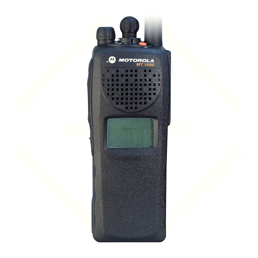
General Radio Operation Physical Features of the MT 1500 Model 1.5 Radio Item Page Item Page Antenna On/Off/Volume Control Knob Top Button Microphone (programmable) Light Emitting Diode 10 Top Side (Select) (LED) Button (programmable) Speaker 11 Push-to-Talk (PTT) Button Universal Connector 12 Side Button 1 (programmable) Channel Selector... -
Page 16: Programmable Features
General Radio Operation Programmable Features The programmable controls on your radio can be programmed by a qualified technician to operate certain software-activated features. The features that can be assigned to these controls, and the page numbers where these features can be found, are listed below. Table 1: Programmable Features Feature Page... -
Page 17: Display
General Radio Operation Display MAEPF-27252-O This figure is typical of what you see on your radio. The 64 x 96 pixel liquid crystal display (LCD) shows radio status, text, and menu entries. Backlight If poor light conditions make the display difficult to read, turn on the radio’s backlight by pressing the Light button. -
Page 18: Status Symbols
General Radio Operation Status Symbols The top two rows in the display contain symbols indicating the radio’s status. Table 2: Status Symbols Symbol Indication Page Call Received. Blinks when a Private Call is received. View Mode. View a list. Received Signal Strength Indication (RSSI). The received signal strength for the current site. -
Page 19: Light Emitting Diode (Led) Indicators
General Radio Operation Light Emitting Diode (LED) Indicators Table 3: LED Indicators This LED Color: Indicates: RED (Illuminated) Transmitting • Channel Busy RED (Blinking) • Low Battery (lights while transmitting) GREEN (Blinking) Receiving Individual Call Alert Tones Your radio uses alert tones to inform you of radio conditions. Table 4: Alert Tones You hear: Tone Name... - Page 20 General Radio Operation Table 4: Alert Tones (Continued) You hear: Tone Name Heard: when the radio is set to an Invalid Mode unprogrammed channel. Long, Low-Pitched when the radio is in Individual Individual Call Tone Call without any activity for Warning Tone more than 6 seconds.
- Page 21 General Radio Operation Table 4: Alert Tones (Continued) You hear: Tone Name Heard: Failsoft when the trunking system fails. when the voice channel is Automatic Call Back available from the previous request. A Group of (when pressing the PTT Medium- Talk Permit button) verifies the system is Pitched...
-
Page 22: Standard Accessories
Prior to using a new battery, charge it for a minimum of 16 hours to ensure optimum capacity and performance. For a list of Motorola approved batteries available for use with your MT 1500 radio, see “Batteries” on page 48. - Page 23 General Radio Operation Attach the Battery With the radio off, fit the three extensions at the bottom of the battery into the bottom slots on the radio. Press both sides at the top of the battery against the radio until both latches click into place.
- Page 24 General Radio Operation Smart Battery Condition This feature allows you to view the condition of your Smart Battery. Press the Smart Battery CAPACITY button. INIT 10/01 EST CHGS Note: If a Smart Battery is not SMART BATT powering your radio: DATA NOT AVAILABLE Press the Smart Battery button again to exit.
-
Page 25: Antenna
General Radio Operation Antenna For information regarding other available antennas, see page 47. Attach the Antenna With the radio off, turn the antenna clockwise to attach Remove the Antenna With the radio off, turn the antenna counterclockwise to remove it. MT 1500 Model 1.5... -
Page 26: Belt Clip
General Radio Operation Belt Clip Attach the Belt Clip Align the grooves of the belt clip with those of the battery. Press the belt clip downward until you hear a “click.” Remove the Belt Clip Use a flat-bladed screwdriver to press the belt clip tab away from the battery. -
Page 27: Universal Connector Cover
General Radio Operation Universal Connector Cover The universal connector cover is located on the antenna side of the radio. It is used to connect certain accessories to the radio. Note: To prevent damage to the connector, shield it with the connector cover when not in use. -
Page 28: Remote Speaker Microphone Adapter
Attach the Adapter With the Motorola side of the adapter facing out, snap the smaller end of the adapter into place in the shroud indent, below the On/Off Volume Control Knob. -
Page 29: Radio On And Off
General Radio Operation Radio On and Off Turn the Radio On Turn the On/Off/Volume Control knob clockwise. • If the power-up test is successful, you will briefly SELF TEST see SELF TEST and then the home display. • If the power-up test is unsuccessful, you will see ERROR XX/YY ERROR XX/YY. -
Page 30: Zones And Channels
General Radio Operation Zones and Channels A zone is a grouping of channels. A channel is a group of radio characteristics, such as transmit/receive frequency pairs. Before you use your radio to receive or send messages, you should select the zone. Select a Zone If a control on your radio has FIRE... -
Page 31: Mode Select Button
General Radio Operation Mode Select Button This feature lets you program the current zone and channel to a Mode Select button with a long press on the Mode Select button. After the buttons are programmed, you can return to the pre- programmed zone and channel with a short press on the programmed Mode Select button. -
Page 32: Receive / Transmit
General Radio Operation Receive / Transmit Radio users who switch from analog to digital radios often assume that the lack of static on a digital channel is an indication that the radio is not working properly. This is not the case. Digital technology quiets the transmission by removing the “noise”... -
Page 33: Use The Preprogrammed Volume Set Button
General Radio Operation Use the Preprogrammed Volume Set Button Turn the radio on and select the desired zone and channel. See Turn the Radio On, page 17 and Zones and Channels, page Press and hold the Volume Set button to hear the volume set tone. -
Page 34: Use The Preprogrammed Monitor Button
General Radio Operation Use the Preprogrammed Monitor Button Turn the radio on and select the desired zone and channel. Press the Monitor button and listen for activity. (See the following Conventional Mode Operation.) Adjust the Volume Control knob if necessary. Press and hold the PTT button to transmit. -
Page 35: Conventional Mode Operation
General Radio Operation Conventional Mode Operation ® Your radio may be programmed to receive Private-Line (PL) calls. Momentarily press the Monitor button to listen for activity. Press and hold the Monitor button to set continuous monitor operation. (The duration of the button press is programmable.) Press the Monitor button again, or the PTT button, to... - Page 36 General Radio Operation Notes...
-
Page 37: Common Radio Features
Common Radio Features Selectable Power Level This feature lets you select the power level at which your radio will transmit. The radio will always turn on to the preprogrammed default setting. This feature must be programmed by a qualified radio technician. -
Page 38: Pl Defeat
Common Radio Features PL Defeat With this feature, you can override any coded squelch (DPL, PL, or network ID) that might be programmed to a channel. Place the preprogrammed PL Defeat switch in the PL Defeat position. You can now hear any activity on the channel. -
Page 39: Emergency
Common Radio Features Emergency If the top (orange) button is programmed to send an emergency signal, then this signal overrides any other communication over the selected channel. Your radio can be programmed for the following: • Emergency Alarm • Emergency Alarm with Emergency Call •... - Page 40 Common Radio Features When you receive the ACK RECEIVED dispatcher’s • Four tones acknowledgment, you see • Alarm ends ACK RECEIVED, four tones sound, the alarm ends, and • Radio exits emergency the radio exits the emergency mode. If no acknowledgement is NO ACKNOWLDG received, you see NO ACKNOWLDG, the alarm ends,...
-
Page 41: Send A Silent Emergency Alarm
Common Radio Features Send a Silent Emergency Alarm With your radio turned on, • Display does not change press the Emergency • LED does not light button. The display does not • No tones change, the LED does not light, and you hear no tones. Note: To exit emergency at any time, press and hold the Emergency button for about a second. - Page 42 Common Radio Features Press and hold the PTT button and announce your emergency into the microphone. Release the PTT button to end the transmission and wait for a response from the dispatcher. Press and hold the Emergency button for about a second to exit emergency.
-
Page 43: Emergency Keep-Alive
Common Radio Features Emergency Keep-Alive With Emergency Keep-Alive enabled, if the radio is in the Emergency state, you cannot turn off the radio by using the On/Off Volume Control knob. With Keep-Alive, the radio will only exit the Emergency state using one of the ways mentioned in the previous sections (Emergency Alarm, Silent Emergency Alarm, or Emergency Call). -
Page 44: Scan List Empty
Common Radio Features Scan List Empty If the scan list has no members, EMPTY LIST is EMPTY LIST displayed. EMPTY LIST can be changed by turning scan off, or a qualified technician adds members to the scan list. Delete a Nuisance Channel When the radio scans to a channel that you do not wish to hear (nuisance channel), you can temporarily delete the channel from the scan list. -
Page 45: Conventional Scan Only
Common Radio Features Conventional Scan Only Make a Dynamic Priority Change While the radio is scanning, the dynamic priority change feature lets you temporarily change any channel in a scan list (except the priority-one channel) to the priority-two channel. The replaced priority-two channel becomes a non-priority channel. -
Page 46: Telephone Calls (Trunking Only)
Common Radio Features Telephone Calls (Trunking Only) Use your radio to receive standard phone calls. A landline phone can be used to call a radio. Answer a Phone Call When a phone call is received, you hear a telephone-type ringing, the PHONE CALL LED blinks Green, the •... -
Page 47: Private Calls (Trunking Only)
Common Radio Features Private Calls (Trunking Only) These one-to-one calls between two radios are not heard by others in the current talkgroup. The calling radio automatically verifies that the receiving radio is active on the system and that it can display the caller’s ID. -
Page 48: Call Alert Paging
Common Radio Features Call Alert Paging Call Alert allows your radio to work like a pager. Answer a Call Alert Page When a Call Alert Page is received, you hear four repeating alert tones, the PAGE RECEIVD LED blinks Green the •... -
Page 49: Special Radio Features
Special Radio Features PTT ID Transmit Your radio’s ID number is automatically sent every time the PTT button is pressed. This is a per-channel feature. For digital voice transmissions, your radio’s ID is sent continuously during the voice message. Trunking System Controls Failsoft The failsoft system ensures continuous radio communications during a trunked system failure. -
Page 50: Out-Of-Range
Special Radio Features Out-of-Range If you go out of the range of the system, and can no longer lock onto a control channel: The display shows OUT OF Your radio’s ID OUT OF RANGE RANGE and the currently selected zone/channel combination, and/ AND/OR or you hear a low-pitched tone. -
Page 51: Site View And Change
Special Radio Features Site View and Change View the Current Site Momentarily press the preprogrammed Site Search button. The display shows either the number of the current site SITE 2 and its corresponding Received Signal Strength Indicator (RSSI) symbol ). (See Table 2 on page 6.) If the radio is scanning for a new site, the display... - Page 52 Special Radio Features Notes...
-
Page 53: Helpful Tips
Helpful Tips Radio Care Cleaning To clean the external surfaces of your radio: Combine one teaspoon of mild dishwashing detergent to one gallon of water (0.5% solution). Apply the solution sparingly with a stiff, non-metallic, short-bristled brush, making sure excess detergent does not get entrapped near the connectors, controls or crevices. -
Page 54: Service
Helpful Tips Service Proper repair and maintenance procedures will assure efficient operation and long life for this product. A Motorola maintenance agreement will provide expert service to keep this and all other communication equipment in perfect operating condition. A nationwide service organization is provided by Motorola to support maintenance services. -
Page 55: Charging The Battery
Helpful Tips Charging the Battery Motorola batteries are designed specifically to be used with a Motorola charger and vice-versa. Charging in non-Motorola equipment may lead to battery damage and void the battery warranty. Motorola-authorized battery chargers may not charge batteries other than the ones listed on page 48. -
Page 56: Battery Recycling And Disposal
Motorola fully endorses and encourages the recycling of NiCd batteries. In the U.S. and Canada, Motorola participates in the nationwide Rechargeable Battery Recycling Corporation (RBRC) program for NiCd battery collection and recycling. Many retailers and dealers participate in this program. -
Page 57: Antenna
Helpful Tips Antenna Radio Operating Frequencies Before installing the antenna, make sure it matches your radio’s operating frequency. Antennas are frequency sensitive and are color coded according to their frequency range. The color code indicator is located in the center of the antenna’s base. - Page 58 Helpful Tips Notes...
-
Page 59: Accessories
Accessories Accessories Motorola provides the following approved accessories to improve the productivity of your MT 1500 portable two-way radio. For a list of Motorola-approved antennas, batteries, and other accessories, visit the following web site which lists approved accessories: http://www.motorola.com/governmentandenterprise/ Antennas NAD6563 VHF whip (136–174 MHz) -
Page 60: Batteries
* Batteries include an over-discharge protection circuit (similar to those in Li-Ion batteries) to extend life of batteries by preventing excessive battery discharge during customer use. Motorola strongly recommends charging these batteries with Motorola-approved IMPRES desktop charges programmed with version 3.4 of the IMPRES desktop charger software. -
Page 61: Chargers
Accessories Chargers NLN7967 Wall-mount kit for multi-unit charger NLN7968 Rack-mount kit for multi-unit charger NTN1168 Single-unit dual rate, rapid charger 120V NTN1169 Single-unit dual rate, rapid charger 220V (2-prong Euro plug) NTN1170 Single-unit dual rate, rapid charger 240V (3-prong UK plug) NTN1177 Multi-unit, dual rate, rapid charger 110V... -
Page 62: Microphones, Remote Speaker
Accessories Microphones, Remote Speaker NMN6191 Remote speaker mic, noise-canceling (includes 6.0-ft. coiled cord assembly, 3.5-mm earjack, swivel clip, quick disconnect) NMN6193 Remote speaker mic NNTN4285 Remote speaker mic adapter RMN5074 18 inch Public Safety Microphone, straight cable RMN5073 24 inch Public Safety Microphone, straight cable RMN5072 30 inch Public Safety Microphone, straight cable ZMN6031... -
Page 63: Earpieces
Accessories Earpieces BDN6641 Ear mic, high noise level up to 105 dB, grey (must order BDN6671 interface module) BDN6664 Earpiece with standard earphone, beige BDN6665 Earpiece with extra-loud earphone (exceeds OSHA limits), beige BDN6666 Earpiece with volume control, beige BDN6667 Earpiece, mic and PTT combined, beige BDN6668 Earpiece, mic and PTT separate, beige... -
Page 64: Headsets And Headset Accessories
Accessories Headsets and Headset Accessories BDN6635 Heavy-duty VOX headset with noise-canceling boom mic (requires BDN6673 adapter) BDN6636 Heavy-duty VOX headset with throat mic (requires BDN6673) BDN6645 Noise-canceling boom mic headset with PTT on earcup NMN1020 Safety helmet headset (requires BDN6676 adapter) NMN6245 Light-weight headset NMN6246... -
Page 65: Appendix: Maritime Radio Use In The Vhf Frequency Range
Appendix: Maritime Radio Use in the VHF Frequency Range Appendix: Maritime Radio Use in the VHF Frequency Range Special Channel Assignments Emergency Channel If you are in imminent and grave danger at sea and require emergency assistance, use VHF Channel 16 to send a distress call to nearby vessels and the United States Coast Guard. -
Page 66: Non-Commercial Call Channel
Appendix: Maritime Radio Use in the VHF Frequency Range 11 If you do not receive an immediate response, remain by the radio and repeat the transmission at intervals until you receive a response. Be prepared to follow any instructions given to you. Non-Commercial Call Channel For non-commercial transmissions, such as fishing reports, rendezvous arrangements, repair scheduling, or berthing... - Page 67 Appendix: Maritime Radio Use in the VHF Frequency Range Table A-1: VHF Marine Channel List (Continued) Frequency (MHz) Channel Number Transmit Receive 156.250 160.850 156.300 – 156.350 160.950 156.400 – 156.450 156.450 156.500 156.500 156.550 156.550 156.600 156.600 13** 156.650 156.650 156.700 156.700...
- Page 68 Appendix: Maritime Radio Use in the VHF Frequency Range Table A-1: VHF Marine Channel List (Continued) Frequency (MHz) Channel Number Transmit Receive 156.225 160.825 156.275 160.875 156.325 160.925 67** 156.375 156.375 156.425 156.425 156.475 156.475 156.575 156.575 156.625 – 156.675 156.675 156.725 156.725...
-
Page 69: Glossary
A channel that has traffic on it. Analog Signal An RF signal that has a continuous nature rather than a pulsed or discrete nature. ASTRO 25 Trunking Motorola standard for wireless digital trunked communications. ASTRO Motorola standard for wireless analog or Conventional digital conventional communications. - Page 70 Glossary Digital Private Line A type of coded squelch using data bursts. (DPL) Similar to PL except a digital code is used instead of a tone. Digital Signal An RF signal that has a pulsed, or discrete nature, rather than a continuous nature. Dispatcher An individual who has radio system management duties.
- Page 71 Glossary Network Access Network Access Code (NAC) operates on Code digital channels to reduce voice channel interference between adjacent systems and sites. NiCd Nickel Cadmium. NiMH Nickel Metal Hydride. Non-Tactical/Revert The user will talk on a preprogrammed emergency channel. The emergency alarm is sent on this same channel.
- Page 72 Glossary Repeater A conventional radio feature, where you talk through a receive/transmit facility (repeater), that re-transmits received signals in order to improve communications range and coverage. Selective Switch Any digital P25 traffic having the correct Network Access Code and the correct talkgroup.
-
Page 73: Commercial Warranty
Product Accessories One (1) Year Motorola, at its option, will at no charge either repair the Product (with new or reconditioned parts), replace it (with a new or reconditioned Product), or refund the purchase price of the Product during the warranty period provided it is returned in accordance with the terms of this warranty. - Page 74 Commercial Warranty MOTOROLA cannot be responsible in any way for any ancillary equipment not furnished by MOTOROLA which is attached to or used in connection with the Product, or for operation of the Product with any ancillary equipment, and all such equipment is expressly excluded from this warranty.
- Page 75 Product item, transportation and insurance prepaid, to an authorized warranty service location. Warranty service will be provided by Motorola through one of its authorized warranty service locations. If you first contact the company which sold you the Product, it can facilitate your obtaining warranty service.
- Page 76 A) that MOTOROLA will be notified promptly in writing by such purchaser of any notice of such claim; B) that MOTOROLA will have sole control of the defense of such suit and all negotiations for its settlement or compromise; and C) should the Product or parts become, or in MOTOROLA’s...
- Page 77 Product or parts as established by MOTOROLA. MOTOROLA will have no liability with respect to any claim of patent infringement which is based upon the combination of the Product or parts furnished hereunder with software, apparatus or devices not...
- Page 78 Commercial Warranty Notes...
-
Page 79: Index
Index chargers ........49 enhanced and multi-unit accessories line cords ....... 49 antennas .........47 conventional mode operation ..23 batteries ........48 belt clips ........48 body-worn .......48 carry accessories ....48 display .......... 5 chargers ........49 display status symbols ....6 Commport integrated microphone/receivers ....50 earpieces .........51 emergency... - Page 80 Index PL defeat ........26 ear microphones ....52 programmable features ....4 switches ........52 PTT ID .........37 time-out timer ......26 radio ID number ......37 Trunking System Controls ..37 receive / transmit turn the radio off ......17 use the preprogrammed turn the radio on ......
- Page 82 Motorola, Inc. 1301 E. Algonquin Rd. Schaumburg, IL60196-1078, USA. MOTOROLA, the Stylized M Logo, ASTRO, and SmartZone are registered in the U.S. Patent & Trademark Office. All other product or service names are the property of their respective owners. © 2007, 2008 by Motorola, Inc.
Need help?
Do you have a question about the MT 1500 and is the answer not in the manual?
Questions and answers