ASROCK FM2A55M-VG3 User Manual
User manual
Hide thumbs
Also See for FM2A55M-VG3:
- User manual (61 pages) ,
- Quick installation manual (46 pages) ,
- Manual (43 pages)

Related Manuals for ASROCK FM2A55M-VG3


Summary of Contents for ASROCK FM2A55M-VG3
-
Page 1: User Manual
FM2A55M-VG3 User Manual Version 1.0 Published November 2012 Copyright©2012 ASRock INC. All rights reserved. -
Page 2: Copyright Notice
ASRock. ASRock assumes no responsibility for any errors or omissions that may appear in this manual. With respect to the contents of this manual, ASRock does not provide warranty of any kind, either expressed or implied, including but not limited to the implied warran- ties or conditions of merchantability or fitness for a particular purpose. -
Page 3: Table Of Contents
Contents 1. Introduction ..............5 Package Contents ..............5 Specifications ................6 Unique Features ................ 9 Motherboard Layout ..............13 I/O Panel .................. 14 2. Installation ..............15 Pre-installation Precautions ..............15 CPU Installation ................. 16 Installation of CPU Fan and Heatsink ........16 Installation of Memory Modules (DIMM) ........ - Page 4 3. UEFI SETUP UTILITY ..........33 Introduction ................33 3.1.1 UEFI Menu Bar ..............33 3.1.2 Navigation Keys ............... 34 Main Screen ................34 OC Tweaker Screen..............35 Advanced Screen ..............38 3.4.1 CPU Configuration ............39 3.4.2 North Bridge Configuration ..........40 3.4.3 South Bridge Configuration ..........
-
Page 5: Introduction
In case any modifications of this manual occur, the updated ver- sion will be available on ASRock website without further notice. You may find the latest VGA cards and CPU support lists on ASRock website as well. ASRock website http://www.asrock.com... -
Page 6: Specifications
1.2 Specifications Platform - Micro ATX Form Factor - All Solid Capacitor design - Support for Socket FM2 100W processors - Supports AMD’s Cool ‘n’ Quiet Technology - UMI-Link GEN2 Chipset - AMD A55 FCH (Hudson-D2) Memory - Dual Channel DDR3 Memory Technology - 2 x DDR3 DIMM slots - Support DDR3 1866/1600/1333/1066 non-ECC, un-buffered memory (see CAUTION 1) - Page 7 Certifications - FCC, CE, WHQL - ErP/EuP Ready (ErP/EuP ready power supply is required) * For detailed product information, please visit our website: http://www.asrock.com WARNING Please realize that there is a certain risk involved with overclocking, including adjusting the setting in the BIOS, applying Untied Overclocking Technology, or using third-party overclocking tools.
- Page 8 ® der Windows 8 / 7 / Vista . For Windows 64-bit OS with 64- bit CPU, there is no such limitation. You can use ASRock XFast ® RAM to utilize the memory that Windows cannot use. 3. For the discrete GPUs which support Dual Graphics technology, please refer to http://www.amd.com/us/products/technologies/...
-
Page 9: Unique Features
OS 32-bit CPU. ASRock Instant Boot ASRock Instant Boot allows you to turn on your PC in just a few seconds, provides a much more efficient way to save energy, time, money, and improves system running speed for your sys- tem. - Page 10 ASRock XFast RAM ASRock XFast RAM is a new function that is included into AS- Rock Extreme Tuning Utility (AXTU). It fully utilizes the memory ® space that cannot be used under Windows OS 32-bit CPU.
- Page 11 S4/S5 state. ASRock Easy RAID Installer ASRock Easy RAID Installer can help you to copy the RAID driver from a support CD to your USB storage device. After copying the RAID driver to your USB storage device, please change “SATA Mode”...
- Page 12 UEFI setup. AS- Rock Restart to UEFI technology is designed for those requiring frequent UEFI access. It is included in ASRock’s exclusive all- in-one AXTU tuning program that allows users to easily enter the UEFI automatically when turning on the PC next time.
-
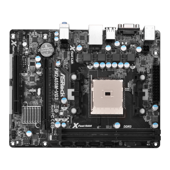
Page 13: Motherboard Layout
1.4 Motherboard Layout ATXPWR1 CPU_FAN1 USB 2.0 T: USB0 B: USB1 USB 2.0 T: USB2 B: USB3 Fast LAN CHA_FAN1 FM2A55M-VG3 RoHS HD_AUDIO1 CMOS PCIE1 BATTERY AUDIO CODEC A55 FCH (Hudson-D2) CLRCMOS1 Chipset 64Mb BIOS USB6_7 USB4_5 PANEL 1 PCI1... -
Page 14: I/O Panel
1.5 I/O Panel PS/2 Mouse Port (Green) USB 2.0 Ports (USB23) LAN RJ-45 Port USB 2.0 Ports (USB01) Line In (Light Blue) D-Sub Port (VGA1) ** 4 Front Speaker (Lime) PS/2 Keyboard Port (Purple) Microphone (Pink) * There are two LED next to the LAN port. Please refer to the table below for the LAN port LED indications. -
Page 15: Installation
2. Installation This is a Micro ATX form factor motherboard. Before you install the motherboard, study the configuration of your chassis to ensure that the motherboard fits into it. Pre-installation Precautions Take note of the following precautions before you install motherboard components or change any motherboard settings. -
Page 16: Cpu Installation
2.1 CPU Installation Step 1. Unlock the socket by lifting the lever up to a 90 angle. Step 2. Position the CPU directly above the socket such that the CPU corner with the golden triangle matches the socket corner with a small triangle. Step 3. -
Page 17: Installation Of Memory Modules (Dimm)
2.3 Installation of Memory Modules (DIMM) This motherboard provides two 240-pin DDR3 (Double Data Rate 3) DIMM slots, and supports Dual Channel Memory Technology. For dual channel configuration, you always need to install two identical (the same brand, speed, size and chip- type) memory modules in the DDR3 DIMM slots to activate Dual Channel Memory Technology. -
Page 18: Expansion Slots (Pci And Pci Express Slots)
2.4 Expansion Slots (PCI and PCI Express Slots) There is 1 PCI slot and 1 PCI Express slot on this motherboard. PCI Slots: PCI slots are used to install expansion cards that have the 32-bit PCI interface. PCIE Slots: PCIE1 (PCIE x16 slot) is used for PCI Express x16 lane width graphics cards. -
Page 19: Dual Graphics Operation Guide
2.5 AMD Dual Graphics Operation Guide This motherboard supports AMD Dual Graphics feature. AMD Dual Graphics brings multi-GPU performance capabilities by enabling an AMD A55 FCH (Hudson-D2) integrated graphics processor and a discrete graphics processor to operate simultaneously with combined output to a single display for blisteringly-fast frame ®... - Page 20 Step 7. You can also click “AMD VISION Engine Control Center” on your ® Windows taskbar to enter AMD VISION Engine Control Center. AMD VISION Engine Control Center Step 8. In AMD VISION Engine Control Center, please choose “Performance”. Click “AMD CrossFire ”.
-
Page 21: Multi Monitor Feature
2.6 Multi Monitor Feature This motherboard supports multi monitor upgrade. With the internal VGA output sup- port and external add-on PCI Express VGA cards, you can easily enjoy the benefits of surround display feature. Please refer to the following steps to set up a surround display environment: 1. - Page 22 D. Repeat steps A through C for the display icon identified by the numbers. 6. Use multi monitor feature. Click and drag the display icons to positions representing the physical setup of your monitors that you would like to use. The placement of display icons determines how you move items from one monitor to another.
-
Page 23: Jumpers Setup
2.7 Jumpers Setup The illustration shows how jumpers are setup. When the jumper cap is placed on pins, the jumper is “Short”. If no jumper cap is placed on pins, the jumper is “Open”. The illustration shows a 3-pin jumper whose pin1 and pin2 are “Short”... -
Page 24: Onboard Headers And Connectors
2.8 Onboard Headers and Connectors Onboard headers and connectors are NOT jumpers. Do NOT place jumper caps over these headers and connectors. Placing jumper caps over the headers and connectors will cause permanent damage of the motherboard! Serial ATA2 Connectors These four Serial ATA2 (SATA2) connectors support (SATA_1: see p.13, No. -
Page 25: Front Panel Audio Header
Front Panel Audio Header This is an interface for the front PRESENCE# panel audio cable that allows (9-pin HD_AUDIO1) MIC_RET OUT_RET convenient connection and (see p.13 No. 20) control of audio devices. OUT2_L J_SENSE OUT2_R MIC2_R MIC2_L 1. High Definition Audio supports Jack Sensing, but the panel wire on the chassis must support HDA to function correctly. - Page 26 HDLED (Hard Drive Activity LED): Connect to the hard drive activity LED on the chassis front panel. The LED is on when the hard drive is reading or writing data. The front panel design may differ by chassis. A front panel module mainly consists of power switch, reset switch, power LED, hard drive activity LED, speaker and etc.
- Page 27 ATX Power Connector Please connect an ATX power supply to this connector. (24-pin ATXPWR1) (see p.13 No. 3) Though this motherboard provides 24-pin ATX power connector, it can still work if you adopt a traditional 20-pin ATX power supply. To use the 20-pin ATX power supply, please plug your power supply along with Pin 1 and Pin 13.
-
Page 28: Serial Ata2 (Sata2) Hard Disks Installation
2.9 Serial ATA2 (SATA2) Hard Disks Installation This motherboard adopts AMD A55 FCH (Hudson-D2) chipset that supports Serial ATA2 (SATA2) hard disks and RAID (RAID 0, RAID 1 and RAID 10) functions. You may install SATA2 hard disks on this motherboard for internal storage devices. This section will guide you to install the SATA2 hard disks. -
Page 29: Operation Guide
* The SATA2 Hot Plug feature might not be supported by the chipset because of its limitation, the SATA2 Hot Plug support information of our motherboard is indicated in the product spec on our website: www.asrock.com 2. Make sure your SATA2 HDD can support Hot Plug function from your dealer or HDD user manual. -
Page 30: How To Hot Plug A Sata2 Hdd
How to Hot Plug a SATA2 HDD: Points of attention, before you process the Hot Plug: Please do follow below instruction sequence to process the Hot Plug, improper procedure will cause the SATA2 HDD damage and data loss. Please connect SATA power cable 1x4-pin Step 1 Connect SATA data cable to Step 2... -
Page 31: Driver Installation Guide
2.12 Driver Installation Guide To install the drivers to your system, please insert the support CD to your optical drive first. Then, the drivers compatible to your system can be auto-detected and listed on the support CD driver page. Please follow the order from up to bottom side to install those required drivers. -
Page 32: Installing Windows ® 8 / 8 64-Bit / 7 / 7 64-Bit / Vista
® 2.14 Installing Windows 8 / 8 64-bit / 7 / 7 64-bit / Vista Vista 64-bit Without RAID Functions ® If you want to install Windows 8 / 8 64-bit / 7 / 7 64-bit / Vista / Vista 64-bit on your SATA2 HDDs without RAID functions, please follow below steps. -
Page 33: Uefi Setup Utility
3. UEFI SETUP UTILITY 3.1 Introduction ASRock Interactive UEFI is a blend of system configuration tools, cool sound ef- fects and stunning visuals. Not only will it make BIOS setup less difficult but also a lot more amusing. This section explains how to use the UEFI SETUP UTILITY to configure your system. -
Page 34: Navigation Keys
3.1.2 Navigation Keys Please check the following table for the function description of each navigation key. Navigation Key(s) Function Description Moves cursor left or right to select Screens Moves cursor up or down to select items + / - To change option for the selected items <Tab>... -
Page 35: Oc Tweaker Screen
3.3 OC Tweaker Screen In the OC Tweaker screen, you can set up overclocking features. EZ OC Mode You can use this option to adjust EZ overclocking setting. Please note that overclocing may cause damage to your components and motherboard. It should be done at your own risk and expense. - Page 36 Multiplier/Voltage Change This item is set to [Auto] by default. If it is set to [Manual], you may adjust the value of Processor Frequency and Processor Voltage. However, it is recommended to keep the default value for system stability. Boost Frequency Multiplier For safety and system stability, it is not recommended to adjust the value of this item.
- Page 37 DRAM Timing Control DRAM Slot Use this item to view SPD data. DRAM Timing Control Use this item to control DRAM timing. Power Down Enable Use this item to enable or disable DDR power down mode. Bank Interleaving Interleaving allows memory accesses to be spread out over banks on the same node, or accross nodes, decreasing access contention.
-
Page 38: Advanced Screen
3.4 Advanced Screen In this section, you may set the configurations for the following items: CPU Configu- ration, Nouth Bridge Configuration, South Bridge Configuration, Storage Configura- tion, ACPI Configuration and USB Configuration. Setting wrong values in this section may cause the system to malfunction. -
Page 39: Cpu Configuration
3.4.1 CPU Configuration Core C6 Mode Use this item to enable or disable Core C6 mode. The default value is [Enabled]. Package C6 Mode This item appears only when you enable the item “Core C6 Mode”. Use this item to enable or disable Package C6 mode. The default value is [Dis- abled]. -
Page 40: North Bridge Configuration
3.4.2 North Bridge Configuration Primary Graphics Adapter This item will switch the PCI Bus scanning order while searching for video card. It allows you to select the type of Primary VGA in case of multiple video controllers. The default value of this feature is [PCI Express]. Con- figuration options: [Onboard], [PCI] and [PCI Express]. -
Page 41: South Bridge Configuration
3.4.3 South Bridge Configuration Onboard HD Audio Select [Auto], [Enabled] or [Disabled] for the onboard HD Audio feature. If you select [Auto], the onboard HD Audio will be disabled when PCI Sound Card is plugged. Front Panel Select [Auto] or [Disabled] for the onboard HD Audio Front Panel. Onboard LAN This allows you to enable or disable the onboard LAN feature. -
Page 42: Storage Configuration
3.4.4 Storage Configuration SATA Controller Use this item to enable or disable the “SATA Controller” feature. SATA Mode Use this item to adjust SATA Mode. The default value of this option is [AHCI Mode]. Configuration options: [AHCI Mode], [RAID Mode] and [IDE Mode]. Easy RAID Installer Easy RAID Installer can help you to copy the RAID driver from a support CD to your USB storage device. -
Page 43: Super Io Configuration
3.4.5 ACPI Configuration Suspend to RAM Use this item to select whether to auto-detect or disable the Suspend-to- RAM feature. Select [Auto] will enable this feature if the OS supports it. Check Ready Bit Use this item to enable or disable the feature Check Ready Bit. Restore on AC/Power Loss This allows you to set the power state after an unexpected AC/power loss. - Page 44 ACPI HPET table Use this item to enable or disable ACPI HPET Table. The default value is [Enabled]. Please set this option to [Enabled] if you plan to use this moth- ® erboard to submit Windows certification. Please disable CSM when you enable Fast Boot option. The default value is [Enabled].
-
Page 45: Usb Configuration
3.4.6 USB Configuration USB 2.0 Controller Use this item to enable or disable the use of USB 2.0 controller. Legacy USB Support Use this option to select legacy support for USB devices. There are four confi guration options: [Enabled], [Auto], [Disabled] and [UEFI Setup Only]. The default value is [Enabled]. -
Page 46: Tool
3.5 Tool Sound Effect Enable or disable sound effects in the setup utility. System Browser System Browser can let you easily check your current system configura- tion in UEFI setup. OMG(Online Management Guard) Administrators are able to establish an internet curfew or restrict internet access at specified times via OMG. - Page 47 Internet Flash Internet Flash searches for available UEFI firmware updates from our servers. In other words, the system can auto-detect the latest UEFI from our servers and flash them without entering Windows OS. Please note that you must be running on a DHCP configured computer in order to en- able this function.
- Page 48 Would you like to save current setting user defaults? In this option, you are allowed to load and save three user defaults according to your own requirements.
-
Page 49: Hardware Health Event Monitoring Screen
3.6 Hardware Health Event Monitoring Screen In this section, it allows you to monitor the status of the hardware on your system, including the parameters of the CPU temperature, motherboard temperature, CPU fan speed, chassis fan speed, and the critical voltage. CPU Fan 1 Setting This allows you to set the CPU fan 1 speed. -
Page 50: Boot Screen
3.7 Boot Screen In this section, it will display the available devices on your system for you to config- ure the boot settings and the boot priority. Fast Boot Fast Boot minimizes your computer’s boot time. There are three con- figuration options: [Disabled], [Fast] and [Ultra Fast]. - Page 51 Full Screen Logo Use this item to enable or disable OEM Logo. The default value is [En- abled]. AddOn ROM Display Use this option to adjust AddOn ROM Display. If you enable the option “Full Screen Logo” but you want to see the AddOn ROM information when the system boots, please select [Enabled].
-
Page 52: Security Screen
3.8 Security Screen In this section, you may set or change the supervisor/user password for the system. For the user password, you may also clear it. Secure Boot Use this to enable or disable Secure Boot. The default value is [Disabled]. -
Page 53: Exit Screen
3.9 Exit Screen Save Changes and Exit When you select this option, it will pop-out the following message, “Save configuration changes and exit setup?” Select [OK] to save the changes and exit the UEFI SETUP UTILITY. Discard Changes and Exit When you select this option, it will pop-out the following message, “Discard changes and exit setup?”... -
Page 54: Software Support
Click on a specific item then follow the installation wizard to install it. 4.2.4 Contact Information If you need to contact ASRock or want to know more about ASRock, welcome to visit ASRock’s website at http://www.asrock.com; or you may contact your... -
Page 55: Installing Os On A Hdd Larger Than 2Tb
Installing OS on a HDD Larger Than 2TB ® This motherboard is adopting UEFI BIOS that allows Windows OS to be installed on a large size HDD (>2TB). Please follow below procedure to install the operating system. ® 1. Please make sure to use Windows Vista 64-bit (with SP1 or above), ®... -
Page 56: Installing Os On A Hdd Larger Than 2Tb In Raid Mode
Installing OS on a HDD Larger Than 2TB in RAID Mode ® This motherboard is adopting UEFI BIOS that allows Windows OS to be installed on a large size HDD (>2TB). Please follow below procedure to install the operating system. ®... - Page 57 7. And then key in drvcfg –s [Drv number] [Ctrl number] to enter Raid Utility. For example: key in drvcfg –s 4E B5. 8. Choose Logical Drive Main Menu to set up Raid Drive. 9. Choose Logical Drive Create Menu to create a Raid Drive. 10.
- Page 58 11. Press Space on keyboard to toggle checkbox. 12. Choose Ld Size setting, and key in the Raid size. 13. After set up Raid size, please click Start to Create. 14. Press <F10> to exit Utility. 15. During reboot, please press <F11> to enter Boot Manual. Choose UEFI: SCSI CD/DVD Drive.
- Page 59 ® 16. Follow Windows Installation Guide to install OS. ® If you install Windows 8 64-bit / 7 64-bit / Vista 64-bit in a large hard ® disk (ex. Disk volume > 2TB), it may take more time to boot into Windows or install driver/utilities.
- Page 60 B. Disable “Volume Shadow Copy” service. a. Type “computer management” in the Start Menu, then press “Enter”. b. Go to “Services and Applications>Services”; Then double click “Volume Shadow Copy”. c. Set “Startup type” to “Disable” then Click “OK”.
- Page 61 C. Reboot your system. D. After reboot, please start to install motherboard drivers and utilities. ® Windows 8 64-bit / 7 64-bit: A. Please request the hotfix KB2505454 thru this link: http://support.microsoft.com/kb/2505454/ ® B. After installing Windows 8 64-bit / 7 64-bit, install the hotfix kb2505454. (This may take long time;...
Need help?
Do you have a question about the FM2A55M-VG3 and is the answer not in the manual?
Questions and answers