
Related Manuals for ASROCK B75M-ITX


Summary of Contents for ASROCK B75M-ITX
-
Page 1: User Manual
B75M-ITX User Manual Version 1.0 Published March 2012 Copyright©2012 ASRock INC. All rights reserved. -
Page 2: Copyright Notice
In no event shall ASRock, its directors, of cers, employees, or agents be liable for any indirect, special, incidental, or consequential damages (including damages for... -
Page 3: Table Of Contents
2.5 Installation of Memory Modules (DIMM) ......20 2.6 Expansion Slot ........21 (PCI Express Slot) 2.7 Dual Monitor and Surround Display Features ....22 2.8 ASRock Smart Remote Installation Guide ..... 25 2.9 Jumpers Setup ............26 2.10 Onboard Headers and Connectors ......27 2.11 Serial ATA (SATA) / Serial ATA2 (SATA2) / Serial ATA3... - Page 4 3 UEFI SETUP UTILITY ..........36 3.1 Introduction ..............36 3.1.1 UEFI Menu Bar ............ 36 3.1.2 Navigation Keys ........... 37 3.2 Main Screen ..............37 3.3 OC Tweaker Screen ............38 3.4 Advanced Screen ............42 3.4.1 CPU Con guration ..........43 3.4.2 North Bridge Con guration........
-
Page 5: Introduction
In case any modi cations of this manual occur, the updated version will be available on ASRock website without further notice. You may the latest VGA cards and CPU support lists on ASRock website as well. ASRock website http://www.asrock.com If you require technical support related to this motherboard, please visit our website for speci c information about the model you are using. -
Page 6: Specifications
1.2 Specifications Mini-ITX Form Factor: 6.7-in x 6.7-in, 17.0 cm x 17.0 cm Platform - All Solid Capacitor design (100% Japan-made high-quality Conductive Polymer Capacitors) ® - Supports 3 and 2 Generation Intel Core i7 / i5 / i3 in LGA1155 Package - Digi Power Design - 4 + 2 Power Phase Design... - Page 7 - Supports DVI with max. resolution up to 1920x1200 @ 60Hz - Supports D-Sub with max. resolution up to 2048x1536 @ 75Hz - Supports Auto Lip Sync, Deep Color (12bpc), xvYCC and HBR (High Bit Rate Audio) with HDMI (Compliant HDMI monitor is required) (see CAUTION 9) - Supports HDCP function with DVI and HDMI ports - Supports Full HD 1080p Blu-ray (BD) / HD-DVD playback...
- Page 8 - Drivers, Utilities, AntiVirus Software (Trial Version), Support CD CyberLink MediaEspresso 6.5 Trial, ASRock MAGIX Multimedia Suite - OEM - ASRock Extreme Tuning Utility (AXTU) (see CAUTION 11) Unique Feature - ASRock Instant Boot - ASRock Instant Flash (see CAUTION 12)
- Page 9 ® Vista / XP. For Windows OS with 64-bit CPU, there is no such limita- tion. You can use ASRock XFast RAM to utilize the memory that Win- dows ® cannot use. To run the PCI Express in Gen 3 speed, please install an Ivy Bridge CPU.
- Page 10 14 for proper connection. 11. ASRock Extreme Tuning Utility (AXTU) is an all-in-one tool to ne-tune dif- ferent system functions in a user-friendly interface, which includes Hard- ware Monitor, Fan Control, Overclocking, OC DNA and IES. In Hardware Monitor, it shows the major readings of your system.
- Page 11 17. ASRock XFast RAM is a new function that is included into ASRock Ex- treme Tuning Utility (AXTU). It fully utilizes the memory space that cannot ®...
- Page 12 Please note that you must be running on a DHCP con gured computer in order to enable this function. 21. ASRock On/Off Play Technology allows users to enjoy the great audio experience from the portable audio devices, such like MP3 player or mobile phone to your PC, even when the PC is turned off (or in ACPI S5 mode)! This motherboard also provides a free 3.5mm audio cable (op-...
-
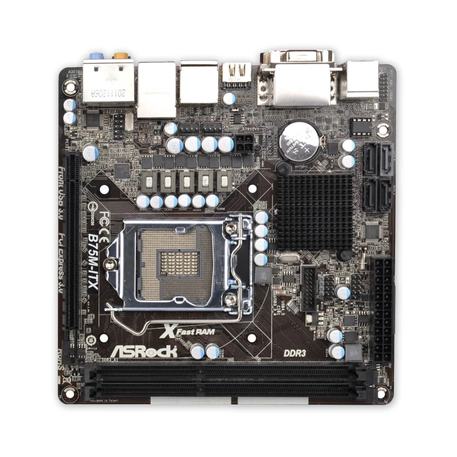
Page 13: Motherboard Layout
CHA_FAN1 T: USB2 B: USB3 CPU_FAN1 USB 3.0 Top: T: USB1 RJ-45 B: USB2 HD_AUDIO1 B75M-ITX AUDIO CODEC PCIE1 PCI Express 3.0 Front USB 3.0 RoHS SPI Flash Memory (64Mb) 2 x 240-pin DDR3 DIMM Slots SATA2 Connector (SATA_1, Black) -
Page 14: I/O Panel
1.4 I/O Panel USB 2.0 Ports (USB01) Microphone (Pink) D-Sub Port (VGA1) Optical SPDIF Out Port USB 2.0 Ports (USB23) USB 3.0 Ports (USB3_12) LAN RJ-45 Port eSATA2 Connector Central / Bass (Orange) HDMI Port (HDMI1) Rear Speaker (Black) DVI-D Port (DVI1) Line In (Light Blue) PS/2 Keyboard Port (Purple) ** 8... - Page 15 To enable Multi-Streaming function, you need to connect a front panel audio cable to the front panel audio header. After restarting your computer, you will nd “Mixer” tool on your system. Please select “Mixer ToolBox” , click “Enable playback multi-streaming”, and click “ok”.
-
Page 16: Installation
Chapter 2: Installation This is a Mini-ITX form factor (6.7" x 6.7", 17.0 x 17.0 cm) motherboard. Before you install the motherboard, study the con guration of your chassis to ensure that the motherboard ts into it. Make sure to unplug the power cord before installing or removing the motherboard. -
Page 17: Cpu Installation
2.3 CPU Installation For the installation of Intel 1155-Pin CPU, please follow the steps below. Load Plate Load Lever Socket Body Contact Array 1155-Pin Socket Overview Before you insert the 1155-Pin CPU into the socket, please check if the CPU surface is unclean or if there are any bent pins in the socket. Do not force to insert the CPU into the socket if above situation is found. - Page 18 Step 3. Insert the 1155-Pin CPU: Step 3-1. Hold the CPU by the edge which is marked with a black line. Step 3-2. Orient the CPU with the IHS (Inte- grated Heat Sink) up. Locate Pin1 and the two orientation key notches. orientation key notch alignment key Pin1...
-
Page 19: Installation Of Cpu Fan And Heatsink
2.4 Installation of CPU Fan and Heatsink This motherboard is equipped with 1155-Pin socket that supports Intel 1155-Pin CPUs. Please adopt the type of heatsink and cooling fan compliant with Intel 1155- Pin CPU to dissipate heat. Before you install the heatsink, you need to spray ther- mal interface material between the CPU and the heatsink to improve heat dissipa- tion. -
Page 20: Installation Of Memory Modules (Dimm)
2.5 Installation of Memory Modules (DIMM) This motherboard provides two 240-pin DDR3 (Double Data Rate 3) DIMM slots, and supports Dual Channel Memory Technology. For dual channel configuration, you always need to install two identical (the same brand, speed, size and chip- type) memory modules in the DDR3 DIMM slots to activate Dual Channel Memory Technology. -
Page 21: Expansion Slot (Pci Express Slot)
2.6 Expansion Slot (PCI Express Slot) There is 1 PCI Express slot on this motherboard. PCIE slots: PCIE1 (PCIE 3.0 x16 slot) is used for PCI Express x16 lane width graphics cards. To run the PCI Express in Gen 3 speed, please install an Ivy Bridge CPU. -
Page 22: Dual Monitor And Surround Display Features
2.7 Dual Monitor and Surround Display Features Dual Monitor Feature This motherboard supports dual monitor feature. With the internal VGA output sup- port (DVI-D, D-Sub and HDMI), you can easily enjoy the bene ts of dual monitor feature without installing any add-on VGA cards to this motherboard. This mother- board also provides independent display controllers for DVI-D, D-Sub and HDMI to support dual VGA output so that DVI-D, D-sub and HDMI can drive same or different display contents. - Page 23 Surround Display Feature This motherboard supports surround display upgrade. With the internal VGA output support (DVI-D, D-Sub and HDMI) and external add-on PCI Express VGA cards, you can easily enjoy the bene ts of surround display feature. Please refer to the following steps to set up a surround display environment: 1.
- Page 24 ® For Windows 7 / 7 64-bit / Vista / Vista 64-bit OS: Right click the desktop, choose “Personalize”, and select the “Display Settings” tab so that you can adjust the parameters of the multi-monitors according to the steps below. A.
-
Page 25: Asrock Smart Remote Installation Guide
The Multi-Angle CIR Receiver does not support Hot-Plug function. Please install it before you boot the system. * ASRock Smart Remote is only supported by some of ASRock's motherboards. Please refer to ASRock's website for the motherboard support list: http://www.asrock.com... -
Page 26: Jumpers Setup
2.9 Jumpers Setup The illustration shows how jumpers are setup. When the jumper cap is placed on pins, the jumper is “Short”. If no jumper cap is placed on pins, the jumper is “Open”. The illustration shows a 3-pin jumper whose pin1 and pin2 are “Short”... -
Page 27: Onboard Headers And Connectors
2.10 Onboard Headers and Connectors Onboard headers and connectors are NOT jumpers. Do NOT place jumper caps over these headers and connectors. Placing jumper caps over the headers and connectors will cause permanent damage of the motherboard! Serial ATA2 Connectors These three Serial ATA2 SATA_2 (SATA2) connectors support... - Page 28 USB 3.0 Header Besides two default USB 3.0 IntA_P0_D+ IntA_P0_D- ports on the I/O panel, there is (19-pin USB3_3_4) IntA_P0_SSTX+ IntA_P0_SSTX- one USB 3.0 header on this (see p.13, No. 12) IntA_P0_SSRX+ motherboard. This USB 3.0 IntA_P0_SSRX- Vbus header can support two USB 3.0 ports.
- Page 29 System Panel Header This header accommodates several system front panel (9-pin PANEL1) functions. (see p.13, No. 8) Connect the power switch, reset switch and system status indicator on the chassis to this header according to the pin assignments below. Note the positive and negative pins before connecting the cables.
- Page 30 Though this motherboard provides 4-Pin CPU fan (Quiet Fan) support, the 3-Pin CPU fan still can work successfully even without the fan speed control function. If you plan to connect the 3-Pin CPU fan to the CPU fan connector on this motherboard, please connect it to Pin 1-3.
-
Page 31: Serial Ata (Sata) / Serial Ata2 (Sata2) / Serial Ata3 (Sata3) Hard Disks Installation
2.11 Serial ATA (SATA) / Serial ATA2 (SATA2) / Serial ATA3 (SATA3) Hard Disks Installation ® This motherboard adopts Intel B75 chipset that supports Serial ATA (SATA) / Serial ATA2 (SATA2) / Serial ATA3 (SATA3) hard disks. You may install SATA / SATA2 / SATA3 hard disks on this motherboard for internal storage devices. -
Page 32: Sata / Sata2 / Sata3 Hdd Hot Plug Feature And Operation Guide
SATA / SATA2 / SATA3 Hot Plug support information of our motherboard is indicated in the product spec on our website: www.asrock.com 2. Make sure your SATA / SATA2 / SATA3 HDD can support Hot Plug function from your dealer or HDD user manual. - Page 33 How to Hot Plug a SATA / SATA2 / SATA3 HDD: Points of attention, before you process the Hot Plug: Please do follow below instruction sequence to process the Hot Plug, improper procedure will cause the SATA / SATA2 / SATA3 HDD damage and data loss. Step 1 Step 2 Please connect SATA power cable 1x4-...
-
Page 34: Driver Installation Guide
2.14 Driver Installation Guide To install the drivers to your system, please insert the support CD to your optical drive rst. Then, the drivers compatible to your system can be auto-detected and listed on the support CD driver page. Please follow the order from up to bottom side to install those required drivers. -
Page 35: Installing Windows ® 7 / 7 64-Bit / Vista
2.15.2 Installing Windows 7 / 7 64-bit / Vista / Vista 64-bit ® Without RAID Functions ® If you want to install Windows 7 / 7 64-bit / Vista / Vista 64-bit OS on your SATA / SATA2 / SATA3 HDDs without RAID functions, please follow below steps. Using SATA / SATA2 / SATA3 HDDs with NCQ function STEP 1: Set Up UEFI. -
Page 36: Uefi Setup Utility
Chapter 3: UEFI SETUP UTILITY 3.1 Introduction This section explains how to use the UEFI SETUP UTILITY to con gure your system. The UEFI chip on the motherboard stores the UEFI SETUP UTILITY. You may run the UEFI SETUP UTILITY when you start up the computer. Please press <F2>... -
Page 37: Navigation Keys
3.1.2 Navigation Keys Please check the following table for the function description of each navigation key. Navigation Key(s) Function Description Moves cursor left or right to select Screens Moves cursor up or down to select items To change option for the selected items + / - Switch to next function <Tab>... -
Page 38: Oc Tweaker Screen
3.3 OC Tweaker Screen In the OC Tweaker screen, you can set up overclocking features. CPU Confi guration CPU Turbo Ratio Use this item to change the ratio value of this motherboard. Intel SpeedStep Technology Intel SpeedStep technology is Intel’s new power saving technology. Pro- cessors can switch between multiple frequencies and voltage points to en- able power saving. - Page 39 Primary Plane Current Limit Use this item to con gure the maximum instantaneous current allowed for the primary plane. The default value is [Auto]. Secondary Plane Current Limit Use this item to con gure the maximum instantaneous current allowed for the secondary plane.
- Page 40 DRAM tRAS Use this item to change RAS# Active Time (tRAS) Auto/Manual setting. The default is [Auto]. Command Rate (CR) Use this item to change Command Rate (CR) Auto/Manual setting. The default is [Auto]. DRAM tWR Use this item to change Write Recovery Time (tWR) Auto/Manual setting. The default is [Auto].
- Page 41 Voltage Confi guration Power Saving Mode Use this to enable or disable Power Saving Mode. The default value is [Disabled]. CPU Voltage Use this to select CPU Voltage. The default value is [Auto]. CPU Load-Line Calibration CPU Load-Line Calibration helps prevent CPU voltage droop when the system is under heavy load.
-
Page 42: Advanced Screen
3.4 Advanced Screen In this section, you may set the con gurations for the following items: CPU Con gu- ration, North Bridge Con guration, South Bridge Con guration, Storage Con gura- tion, Intel(R) Rapid Start Technology, Intel(R) Smart Connect Technology, ACPI Con guration and USB Con guration. -
Page 43: Cpu Configuration
3.4.1 CPU Configuration Intel Hyper Threading Technology To enable this feature, a computer system with an Intel processor that sup- ports Hyper-Threading technology and an operating system that includes ® ® optimization for this technology, such as Microsoft Windows XP / Vista ®... - Page 44 to the IA-32 Intel Architecture. An IA-32 processor with “No Execute (NX) Memory Protection” can prevent data pages from being used by malicious software to execute codes. This option will be hidden if the current CPU does not support No-Excute Memory Protection. Intel Virtualization Technology When this option is set to [Enabled], a VMM (Virtual Machine Architecture) can utilize the additional hardware capabilities provided by Vanderpool...
-
Page 45: North Bridge Configuration
3.4.2 North Bridge Configuration Primary Graphics Adapter This allows you to select [Onboard] or [PCI Express] as the boot graphic adapter priority. The default value is [PCI Express]. VT-d ® ® Use this to enable or disable Intel VT-d technology (Intel Virtualization Technology for Directed I/O). -
Page 46: South Bridge Configuration
3.4.3 South Bridge Configuration Onboard HD Audio Select [Auto], [Enabled] or [Disabled] for the onboard HD Audio feature. If you select [Auto], the onboard HD Audio will be disabled when PCI Sound Card is plugged. Front Panel Select [Auto] or [Disabled] for the onboard HD Audio Front Panel. On/Off Play Use this item to enable or disable On/Off Play Technology. -
Page 47: Storage Configuration
3.4.4 Storage Configuration SATA Controller(s) Use this item to enable or disable the SATA Controller feature. SATA Mode Selection Use this to select SATA mode. Con guration options: [IDE Mode], [AHCI Mode] and [RAID Mode]. The default value is [AHCI Mode]. AHCI (Advanced Host Controller Interface) supports NCQ and other new features that will improve SATA disk performance but IDE mode does not have these advantages. -
Page 48: Intel(R) Rapid Start Technology
3.4.5 Intel(R) Rapid Start Technology Intel(R) Rapid Start Technology Use this item to enable or disable Intel(R) Rapid Start Technology. Intel(R) Rapid Start Technology is a new zero power hibernation mode which al- lows users to resume in just 5-6 seconds. The default is [Enabled]. Entry on S3 RTC Wake Use this item to enable or disable Intel Rapid Start invocation upon S3 RTC wake. -
Page 49: Intel(R) Smart Connect Technology
3.4.6 Intel(R) Smart Connect Technology Intel(R) Smart Connect Technology Use this item to enable or disable Intel(R) Smart Connect Technology. Intel(R) Smart Connect Technology keeps your e-mail and social networks, such as Twitter, Facebook, etc. updated automatically while the computer is in sleep mode. -
Page 50: Acpi Configuration
3.4.7 ACPI Configuration Suspend to RAM Use this item to select whether to auto-detect or disable the Suspend-to- RAM feature. Selecting [Auto] will enable this feature if the OS supports it. Check Ready Bit Use this item to enable or disable the feature Check Ready Bit. ACPI HPET Table Use this item to enable or disable ACPI HPET Table. -
Page 51: Usb Configuration
OMG (Online Management Guard) Administrators are able to establish an internet curfew or restrict internet access at speci ed times via OMG. You may choose from [Everyday], [Day of the week] or [Weekdays and weekends], then schedule the starting and ending hours of internet access granted to other users. -
Page 52: Hardware Health Event Monitoring Screen
3.5 Hardware Health Event Monitoring Screen In this section, it allows you to monitor the status of the hardware on your system, including the parameters of the CPU temperature, motherboard temperature, CPU fan speed, chassis fan speed, and the critical voltage. CPU Fan 1 Setting This allows you to set CPU fan 1’s speed. -
Page 53: Boot Screen
3.6 Boot Screen In this section, it will display the available devices on your system for you to con g- ure the boot settings and the boot priority. Setup Prompt Timeout This shows the number of seconds to wait for setup activation key. 65535(0XFFFF) means inde nite waiting. -
Page 54: Security Screen
3.7 Security Screen In this section, you may set or change the supervisor/user password for the system. For the user password, you may also clear it. -
Page 55: Exit Screen
3.8 Exit Screen Save Changes and Exit When you select this option, the following message “Save con guration changes and exit setup?” will pop-out. Select [Yes] to save the changes and exit the UEFI SETUP UTILITY. Discard Changes and Exit When you select this option, the following message “Discard changes and exit setup?”... -
Page 56: Software Support
Click on a speci c item then follow the installation wizard to install it. 4.2.4 Contact Information If you need to contact ASRock or want to know more about ASRock, welcome to visit ASRock’s website at http://www.asrock.com; or you may contact your... -
Page 57: Storage Con Guration
Installing OS on a HDD Larger Than 2TB in AHCI Mode ® This motherboard adopts UEFI BIOS that allows Windows OS to be installed on a large size HDD (>2TB). Please follow the procedures below to install the operating system. 1.
Need help?
Do you have a question about the B75M-ITX and is the answer not in the manual?
Questions and answers