
Related Manuals for Emerson Copeland Scroll SZO22


Summary of Contents for Emerson Copeland Scroll SZO22
- Page 1 Copeland Scroll Compressor Module ® Installation, Operation & Maintenance Manual Model Family SZO22 SZV22...
-
Page 3: Table Of Contents
Single-Compressor Module TABLE OF CONTENTS TABLE OF CONTENTS ..................... ompressor odule omeNClature .......................1 mportaNt afety NformatioN ........................3 NtroduCtioN The Compressor Module ......................3 The Compressor ........................... 4 The Compressor Package ......................4 ........................5 NstallatioN Installation Guidelines ........................5 2.1.1 Required Component—Inlet Gas Scrubber ..................5 2.1.2 General Installation Guidelines ......................5 Inlet and Discharge Pressures ...................... - Page 4 Single-Compressor Module TABLE OF CONTENTS Maintenance Tools ........................18 Oil Service ..........................19 Cleaning the Inlet Screen ......................21 Servicing the Scavenge Line Orifice ................... 21 Changing the Second-Stage Separator Element................ 21 ......................22 roubleshootiNg Troubleshooting Guide ....................... 22 Motor Winding Resistance ......................22 Platform Symptoms Diagnosis ....................
- Page 5 Single-Compressor Module TABLE OF CONTENTS FIGURES Figure 1 Compressor Module Components ......................3 Figure 2 Copeland Scroll Compressor Cross Section ..................4 ® Figure 3 Typical Compressor Package .......................4 Figure 4 Compressor Module Dimensions, in. (mm) ....................7 Figure 5 Compressor Module Gas and Oil Flow Diagram and Safety Shutdowns ..........8 Figure 6 Brushless DC Fan ..........................10 Figure 7...
-
Page 6: Compressor Module Nomenclature
Single-Compressor Module Compressor Module Nomenclature ompressor odule omeNClature High Thermal Press High Bypass Delivery Switch Press Temp Valve Module Pressure Flow Drive Setting Switch Setting Setpoint Bypass Weight Model (PSIG) (MCFD) (PSIG) Setting °F (°C) °F (°C) Valve (Lbs.) Single Scroll Units 2”... -
Page 7: I Mportant S Afety I Nformation
Single-Compressor Module Important Safety Information mportaNt afety NformatioN This manual contains important instructions for installation, operation and maintenance of your Copeland Scroll Compressor Module. ® WARNING The Compressor Module must be installed ONLY in systems that have been designed by qualified engineering personnel. - Page 8 Single-Compressor Module Important Safety Information afety ymbols sed iN aNual SAFETY ALERT SYMBOL When you see this symbol on the Compressor Module or in this manual, look for one of the following words and be aware of the potential for personal injury or property damage. WARNING A Warning describes hazards that CAN or WILL cause serious personal injury, death or major property damage.
-
Page 9: Ntroduction
Single-Compressor Module Introduction NtroduCtioN The Copeland Scroll SZO22 Compressor Module comes equipped with one Copeland Scroll ® ® Compressor designed for Class I, Division II applications. The Compressor Module is designed for assembly into a Compressor Package ready for service in the field; the completed housing is done by equipment Packagers. -
Page 10: The Compressor
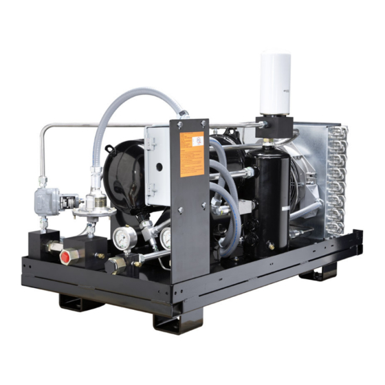
Single-Compressor Module Introduction The Compressor The Compressor refers to the Copeland Scroll Compressor. Figure 2 shows a cross-section of a ® Compressor and its key components. Figure 2 Copeland Scroll Compressor Cross Section (not shown: Encapsulated Stator) ® The Compressor Package The Compressor Package consists of the Compressor Module housed in an assembly ready for service in the field. -
Page 11: Nstallation
Single-Compressor Module Installation NstallatioN Installation Guidelines 2.1.1 Required Component—Inlet Gas Scrubber An appropriate inlet gas scrubber is REQUIRED to remove liquids from the gas prior to compression. If there is potential for liquid slugging, a suitable trap must be installed to prevent liquid from flooding and damaging the Compressor. -
Page 12: Ambient Temperature Range
Single-Compressor Module Installation NOTE: Required Component – High Pressure Discharge Gas Bypass Valve To eliminate redundancy, the high pressure discharge gas bypass (recycle) valve was removed from some of the scroll modules. Packagers will need to install pressure relief downstream of our module. See table on page iv. Ambient Temperature Range The Compressor Module operating ambient temperature is 20°F to +122°F (-29°... -
Page 13: Installation Clearance And Dimensions
Single-Compressor Module Installation Installation Clearance and Dimensions Allow sufficient clearance on all sides for service access, especially for gas and electrical connections at the rear of the Compressor Module. Check applicable national and local electrical codes. Cooling air flow is back to front—from the gas connection end to the oil cooler end. Do not block or restrict the cooler fans or oil cooler. -
Page 14: Process And Instrumentation Diagrams (P&Ids)
Single-Compressor Module Installation Process and Instrumentation Diagrams (P&IDs) Figure 5 Compressor Module Gas and Oil Flow Diagram and Safety Shutdowns Single Compressor Module Gas & Oil Flow Diagram & Safety Shutdowns (Gas bypass valve shown is optional) 2008SSD-34 (5/11) -
Page 15: Electrical Controls
Single-Compressor Module Installation Electrical Controls 2.6.1 General Considerations All shutdown devices are dry contact switches rated Class I, Division II that are wired to a terminal box for connection to the packager supplied control circuit. The common wires on all switches are connected together. -
Page 16: Oil Cooler Fan Control
Single-Compressor Module Installation 2.6.2 Oil Cooler Fan Control The Compressor Module temperature is controlled by managing module oil flow and temperature. The module’s precise temperature control is critical to system performance and equipment life. Maintaining proper temperature control also reduces the possibility of gas condensing into liquids during operation. •... -
Page 17: Figure 8 Optional Customer-Installed High Temperature Fan Control System
Single-Compressor Module Installation Figure 8 Optional Customer-Installed High Temperature Fan Control System • Compressor requirements: 0.8 to 2 GPM (3.0-755 LPM) flow rate • Thermal oil bypass valve, standard setting: 200°F (93°C) / 250°F model specific • Thermal bypass valve operation (valve’s purpose is to provide discharge temperature control) •... -
Page 18: Compressor Module Motor Protection
Single-Compressor Module Installation 2.6.3 Compressor Module Motor Protection Variable Speed Compressor Module Protection • The VFD provides overload protection for the compressor. • Module capacity can be changed by varying the typical Compressor speed, ranging from 2400 to 4800 rpm. Figure 10 Motor Control 2008SSD-34 (5/11) -
Page 19: Electrical Requirements
Single-Compressor Module Installation 2.6.4 Electrical Requirements Figure 11 Typical Compressor Module Electrical Requirements Code Description Control Techniques VFD,* 10 or 15 HP model specific 24VDC power supply ** Optional if more than one Optional if more than one PLC or other control for inputs from compressor module used Compressor Module used Compressor Module... -
Page 20: Wiring
Single-Compressor Module Installation 2.6.5 Wiring Figure 12 Control Circuit Terminations Control Wiring Terminations 2008SSD-34 (5/11) -
Page 21: Variable Frequency Drive (Vfd) Terminations
Single-Compressor Module Installation 2.6.6 Variable Frequency Drive (VFD) Terminations Refer to Product Bulletin on Variable Frequency Drive Applications for details on VFD terminations and typical VFD parameters. peratioN Initial Startup - Compressor Module The following inspections should be made on initial startup—-typically, by the Packager—and after long periods of storage. -
Page 22: Post-Startup Checklist
Single-Compressor Module Operation 3.1.2 Post-Startup Checklist Perform these checks AFTER starting the Compressor Module: DURING INITIAL OPERATION, PERFORM THESE CHECKS: ___ 1. Compressor Module builds pressure on initial startup; no unusual mechanical noise. ___ 2. Oil level is correct at minimum and maximum speeds. ___ 3. -
Page 23: M Aintenance
Single-Compressor Module Operation aiNteNaNCe Routine Maintenance Perform the maintenance procedures in Table 5 at least once per year or more often if needed. Oil consumption varies by application and during initial operation. Monitor the oil level routinely to determine a consistent pattern of actual consumption. Table 3 Maintenance summary Components... -
Page 24: Maintenance Tools
Single-Compressor Module Maintenance Maintenance Tools Figure 15 shows the tools needed for maintenance of the Compressor Module. Contact the Packager to obtain a maintenance tool kit. These are typical air conditioning and refrigeration service tools. Figure 13 Maintenance Tools Back-seating Oil pump, piston type, Filter wrench Charging hose... -
Page 25: Oil Service
Single-Compressor Module Maintenance Oil Service The oil level indicated on the first-stage oil separator site glasses varies with inlet and discharge pressures and operating speed. • New oil is clear, it may be necessary to use a flashlight to verify the correct oil level. •... - Page 26 Single-Compressor Module Maintenance • Scavenge line orifice or screen is restricted. Clean or replace. • Insufficient back pressure. Confirm 50-60 psig or higher backpressure when the compressor is running. • No specific cause found. Replace oil separator block assembly, scavenge line and secondary oil separator element.
-
Page 27: Cleaning The Inlet Screen
Single-Compressor Module Maintenance Cleaning the Inlet Screen The 30-mesh screen in the inlet block must remain unobstructed for optimal flow rate. If the flow rate is lower than expected even when the Compressor is running properly, this screen may be obstructed. Figure 14 Gas Inlet Block and Screen To inspect and clean the inlet screen: 1. -
Page 28: Changing The Second-Stage Separator Element
Single-Compressor Module Maintenance Changing the Second-Stage Separator Element To replace the second-stage separator element: 1. Turn off and isolate the Compressor from all power sources. 2. Turn off the gas supply. 3. Vent the system to 0 psig. Follow applicable safety procedures and codes. 4. -
Page 29: Platform Symptoms Diagnosis
Single-Compressor Module Maintenance Platform Symptoms Diagnosis Use the following guidelines to troubleshoot operating problems. Table 6 Platform troubleshooting guidelines Problem Recommended Actions • Low inlet pressure • Insufficient gas supply • High temperature Low Gas Flow • Bypass valve open •... -
Page 30: S Pecifications
Single-Compressor Module Maintenance peCifiCatioNs Table 7 Compressor Module Specifications General Information Inlet pressure range Model specific - refer to application envelope Outlet pressure range 70 to 275 psig (depends on model—see page iv) Mechanical Description Module weight Approximately 350 lb. (160kg) Suction connection 1.0”... -
Page 31: A Ppendix A M Aterial D Ata S Afety S Heet
Single-Compressor Module Material Data Safety Sheet a - m ppeNdix aterial afety heet The information in this material safety data sheet should be provided to all who use, handle, store, transport or are otherwise exposed to this product. CPI believes the information in this document to be reliable and up to date as of the date of publication, but makes no guarantee that it is. -
Page 32: Fire And Explosion Hazards
Single-Compressor Module Material Data Safety Sheet a.6 f ire aNd xplosioN azards Flash Point (by Cleveland Open 320-530°F (160-276°C) Cup) Flammable Limits Not established Auto-Ignition Temperature No data Health HMIS Ratings Flammability Reactivity NFPA Ratings Not established Extinguishing Media Dry chemical; CO foam;... - Page 34 Cudahy, WI 53110-8904 P 414 744 0111 F 414744 1769 www.vilter.com Copeland Scroll and Emerson are trademarks of Emerson Electric Co. or one of its affiliated companies. ©2011 Emerson Climate Technoligies, Inc. All rights reserved. Printed in the USA. 2008SSD-34-R2...
Need help?
Do you have a question about the Copeland Scroll SZO22 and is the answer not in the manual?
Questions and answers