Table of Contents
Advertisement
Advertisement
Table of Contents

Summary of Contents for ASTEC NT5C06D
- Page 1 Astec Advanced Power Systems UM5C06D ( 169-2071-504 ) Helios Rectifier 25/48 Single Phase -48V, 25 A Power Factor Corrected Switch Mode Rectifier NT5C06D Installation and User Manual P0831010 Standard 7.00 May 2001 Astec Advanced Power Systems A part of Emerson Network Power...
- Page 3 Astec Advanced Power Systems A part of Emerson Network Power Helios Candeo is a trademark of Astec International Ltd. The Emerson logo is a trademark and service mark of Emerson Electric Co. Helios Rectifier 25/48NT5C06D Installation and User Manual...
-
Page 5: Publication History
Publication history May 2001 Standard issue 7.00. Manual modified to reflect the Emerson identity. ( EC 102-26438 ) September 1999 Standard 6.0. Document modified to be in accordance with Astec standards. (ECN 102-17331) May 1999 Standard 5.0. Document modified to reflect Astec identity. Figure 11 modified. - Page 6 6 Publication history This page is left blank intentionally. UM5C06D ( 169-2071-504 ) P0831010 Standard 7.00 May 2001...
-
Page 7: Table Of Contents
Description... 11 Applications ... 12 Equipment Identification ... 12 MPS75 NT5C10C(X) power shelf (23-inch) ...12 Helios Rectifier 25/48 NT5C06D(X) –48 V / 25 A Switch Mode Rectifier...13 Specifications ... 15 Electrical specifications... 15 Output noise and ripple ...16 Efficiency and Power Factor ...16... - Page 8 8 Contents Forced Load Share ...32 Load Share Adjustment Procedure ...32 Operation... 33 Front panel controls... 34 Features ... 34 Local float / equalize control ...34 High voltage shutdown (HVSD) - local ...34 High voltage shutdown - remote...34 Start-up delay...35 Test points (V+, V-) ...35 Indicators ...35 Rectifier failure alarm (RFA)...35...
- Page 9 Figure 1 - MPS75 Modular Power Shelf-NT5C10C with 8-pin signal cables ...13 Figure 2 - MPS75 Modular Power shelf- NT5C10C with 26-pin signal connectors...14 Figure 3 - NT5C06D Switch Mode Rectifier...14 Figure 4 - Power shelf common AC connection...21 Figure 5 - Power shelf individual AC connection ...22 Figure 6 - Connecting the DC power shelf ...23...
- Page 10 10 Contents This page is left blank intentionally. UM5C06D ( 169-2071-504 ) P0831010 Standard 7.00 May 2001...
-
Page 11: Introduction
1. Introduction Description The NT5C06D Switch Mode Rectifier is rated for 25 A at -48 V DC. This rectifier incorporates AC input power factor correction circuitry, is highly efficient and lightweight (15 lbs.). It is fully connectorized and plugs into a power shelf into which up to three rectifiers can be installed. -
Page 12: Applications
The NT5C06D rectifier is designed to operate continuously in a small or large power system. The NT5C06D is compatible with all other Astec rectifiers, and can be interfaced with other commercially available standard (compatible) rectifiers and power plants. -
Page 13: Helios Rectifier 25/48 Nt5C06D(X) -48 V / 25 A Switch Mode Rectifier
Helios Rectifier 25/48 NT5C06D(X) –48 V / 25 A Switch Mode Rectifier The NT5C06D provides -48 V / 25 A of isolated, filtered, and regulated DC power from a single phase AC source, for powering a load while charging a positive grounded battery. -
Page 14: Figure 2 - Mps75 Modular Power Shelf- Nt5C10C With 26-Pin Signal Connectors
14 Introduction Figure 2 - MPS75 Modular Power shelf- NT5C10C with 26-pin signal connectors Mounting holes (4) Figure 3 - NT5C06D Switch Mode Rectifier Height: Depth: Width: Weight:6.8 kg (15 lbs) OUTPUT SO RTIE UM5C06D ( 169-2071-504 ) P0831010 Standard 7.00 May 2001 Signal cable connection 168 mm (6.60 inches) -
Page 15: Specifications
2. Specifications Electrical specifications The NT5C06D rectifier operates within the electrical specifications listed in Table 1. (Refer to the Product Specification which can be obtained from the Engineering department of Astec Advanced Power Systems). Table 1 - Electrical specifications Input Voltage Rating:... -
Page 16: Output Noise And Ripple
16 Specifications Table 1 - Electrical specifications ( continued ) Output Protection: Output Regulation: Output noise and ripple Less than 22 dBrnC at voice frequency (with or without batteries and measured at the point of regulation) from a 1 A load current to full load, including the current limit mode. -
Page 17: Environmental Specifications
Environmental specifications Operating The rectifier will operate satisfactorily under the following environmental conditions: Temperature Range: NT5C06DA/DB Humidity: Altitude: Transportation During transportation the rectifier can be subjected to the following conditions without sustaining damage: Temperature Range: Humidity: Vibration: Pressure: Temp. Shock: Storage For storage, the rectifier must not be kept in an environment exceeding: Temperature Range:... - Page 18 18 Specifications The rectifier contains aluminum electrolytic capacitors having a shelf life of 5 years or greater when stored at the maximum rated storage temperature. UM5C06D ( 169-2071-504 ) P0831010 Standard 7.00 May 2001...
-
Page 19: Installation And Start Up
Open and box ended wrenches (set) Socket set (1/2-inch drive) Ratchet Wrench (1/2-inch drive) Torque limiting torque wrench (1/2-inch drive) Crimper, T & B 12 or 15 Ton head with 94H die Digital Multimeter, Fluke 8000A or equivalent Helios Rectifier 25/48NT5C06D Installation and User Manual... -
Page 20: Wiring The Power Shelf
20 Installation and start-up Procedure 1 - Installing the power shelf Step Position the power shelf, without any rectifiers plugged in, against the framework. Secure the shelf in the position indicated by the job drawing (normally directly below the controller or another shelf). At least one star washer must be installed on one holding screw to ensure maximum framework ground continuity. -
Page 21: Installing The Ac Power
Installing the AC power Permanent AC connection to the MPS75 power shelf is done using two armored cable conductors, RW-90 or equivalent, as listed in Table 2. One must be routed to L1, and the other one to L2 and to the safety shelf frame ground (FR GND). -
Page 22: Dc Conductors Installation
22 Installation and start-up Figure 5 - Power shelf individual AC connection When cabling the AC to the power shelf, make sure that each corresponding safety ground wire is properly connected to the terminal designated FR GND. This grounding is proven to be sufficient, but for systems requiring an extra ground connection, an 8 AWG cable wire (color green, insulation 105°C) can be installed in addition to the existing cable and be connected to an external system ground. -
Page 23: Control And Alarm Connections
Table 4 - DC cable wire size 1 RECT. POSITION 8 AWG Figure 6 - Connecting the DC power shelf Control and Alarm Connections The rectifier is interfaced to the power plant controller through the signal connectors provided on the backplane of the power shelf (see Figures 1 and 2 for location). -
Page 24: Table 5 - Rectifier And Controller Interface Connections (8-Pin Connectors)
24 Installation and start-up Table 5 - Rectifier and Controller interface connections (8-pin connectors) Pin # Design. FAN ALM HVSDR HVSD Note: Table 6 - Rectifier and Controller interface connections (26-pin connector) Pin # Designation RC1 - RFA1 (NC) SH1+ SH1- RC2- RFA2 (NC) - Page 25 Table 6 - Rectifier and Controller interface connections (26-pin connector) ( continued ) Pin # Designation DC BRK ALM AC FAIL ALM SENSE FAIL FAN ALM Note: In applications where no controller is available or desired, the current sharing functions among rectifiers in SLOPE or FORCE mode are still available. The signal cable remote sense connections RC- and RG+ must be connected to the desired remote sensing location ( batteries).
-
Page 26: Figure 7 - No Controller, Remote Sensing Connection For 8-Pin Signal Cable Shelves
26 Installation and start-up Figure 7 - No controller, remote sensing connection for 8-pin signal cable shelves Note 1: Note 2: Note 3: Note 4: UM5C06D ( 169-2071-504 ) P0831010 Standard 7.00 May 2001 Refer to MS5C06 for available 8-pin ribbon signal cables of different lengths to connect from the shelf back plane rectifier position to the remote sensing point. -
Page 27: Figure 8 - No Controller, Remote Sensing Connection For A 26-Pin Signal Connector
Figure 8 - No controller, remote sensing connection for a 26-pin signal connector shelf 26 pins ribbon connector m ate SIG N A L see note 1 ) Note 1: Note 2: Note 3: Note 4: 20 AWG (SEE NO TE 3) RC FUSE RG + C A B LES... -
Page 28: Verification
Reinstall the AC and DC junction box cover on the left and right sides. Installing the rectifier The NT5C06D rectifier is a plug-in unit intended for use in the MPS75 power shelf. Procedure 3 - Rectifier installation procedure... -
Page 29: Rectifier Meter Accuracy
Rectifier meter accuracy The rectifier's current meter is precise within + 2%. Start-up and verification Repeat the following steps for each rectifier in turn. Procedure 4 - Starting up the rectifier Step Close the AC circuit breaker in the AC service (main) panel. Connect an external meter to test points V- and V+ on the rectifier to be tested. - Page 30 30 Installation and start-up Procedure 4 - Starting up the rectifier ( continued ) Step In order to accurately adjust the rectifiers float and/or equalize (if different from factory setting) the current share mode setting must be taken into account. Two modes of share are offered in the NT5C06DA/DB.
- Page 31 Procedure 4 - Starting up the rectifier ( continued ) Step (ii) Forced Share In the forced share mode, the rectifier's output voltage setting is not modified with changes in output load as is the case in the Slope Share mode.
-
Page 32: Slope Load Share
32 Installation and start-up Slope Load Share When the rectifier is connected in parallel with rectifiers in the same power shelf, or other power shelves, and this method of load sharing is desired, the SLS / FS switch of each rectifier must be pushed towards the SLS. Forced Load Share When the preferred method for load sharing is Forced Load Share, the SLS / FS switch of each rectifier must be pushed toward the FS designation. -
Page 33: Operation
HVSD reset, and fan failure detection. A 2-1/2 digit output current meter displays the output current. An internal logic power supply provides the various voltages required by the logic circuitry and the cooling fan unit. Helios Rectifier 25/48NT5C06D Installation and User Manual... -
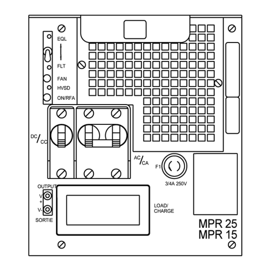
Page 34: Front Panel Controls
34 Operation Front panel controls Figure 9 - NT5C06D - front view Features In addition to the features and performance characteristics described earlier, the rectifier provides the following features. Local float / equalize control The rectifier is equipped with a float / equalize switch. The rectifier normally delivers a float voltage set by the FLT potentiometer. -
Page 35: Start-Up Delay
Start-up delay This unit does not have a start-up delay. Test points (V+, V-) Test points allow the user to measure the voltage at the point of regulation. A 100 ohm PTC resistor is placed in series with both leads to prevent damage caused by short circuits at the jack terminals. -
Page 36: Local On/Off Control (Ac Breaker)
36 Operation Local ON/OFF control (AC breaker) The AC input circuit breaker can be used to locally turn the rectifier ON/OFF. The local ON/OFF control overrides remote control signals. Remote ON/OFF control When a battery return (BAT RTN) signal is applied to the 'Temporary Release' (TR) input, the rectifier inhibits its operation ( no RFA will be transmitted). -
Page 37: Sequential Start
Sequential start The rectifier TR lead is available for use with an external sequential start circuit. Parallel operation The rectifier is capable of operating in parallel with other rectifiers having similar output characteristics and shares the total load proportionally to its output rating. Two load-sharing methods are available: Slope load sharing Forced load sharing (positive bus) -
Page 38: Input Ac Voltage Monitor
38 Operation Input AC voltage monitor The rectifier monitors the input voltage, inhibits its operation and sends an RFA when the AC voltage decreases below 176 or rises above 264 V AC. An AC FAIL alarm contact is transmitted through the signal connector. The rectifier recovers its normal operation automatically when the input voltage returns within the acceptable limits, without any operator intervention. -
Page 39: Signal Interface Connector
Figure 10 - Power interface connections Signal interface connector Figure 11 shows the pin assignment of the signal interface connector. This connector is used to interface all the control, alarm and monitoring signals with the power shelf that, in turn, interfaces these with the Controller. The control inputs are activated by a ground (BAT RTN) signal. -
Page 40: Figure 11 - Control Signal Connections
40 Operation Figure 11 - Control signal connections UM5C06D ( 169-2071-504 ) P0831010 Standard 7.00 May 2001 1 - REMOTE EQL 2 - SENSING RG + 3 - SENSING RC - 4 - TEMPORARY RELEASE 5 - REMOTE HVSD RESET 6 - REMOTE HVSD 7 - RFA NC 8 - Not Connected... -
Page 41: Maintenance
5. Maintenance The NT5C06D rectifier is virtually maintenance free. It requires periodic float / equalize verification (once every six months) and air filter replacement as required. Note: To remove the filter, simply unscrew it. Re-install it by reversing the operation. -
Page 42: High Voltage Shutdown (Hvsd)
42 Maintenance Procedure 6 - Adjusting the float / equalize ( continued ) Step The float voltage should be adjusted with the rectifier in service, as follows: The rectifier is connected to the system and should carry some load. If the rectifier is connected in parallel with other rectifiers, verify that the total system load current is shared equally among the rectifiers. -
Page 43: Fan Replacement
Fan replacement Procedure 7 - Replacing the fan Step Disconnect the 3-pin fan connector located below the fan assembly (refer to Figure 12). With the unit sitting solidly on a clean workbench, carefully remove the four mounting screws that hold the fan assembly in place. Slowly and carefully remove the fan assembly by pulling it from the chassis. -
Page 44: Figure 12 - Nt5C06D Rear View
44 Maintenance Figure 12 - NT5C06D rear view UM5C06D ( 169-2071-504 ) P0831010 Standard 7.00 May 2001 CAUTION Ensure that the fans spin freely, without interference. -
Page 45: Power Shelf
Maintenance 45 CAUTION Do not run the rectifier without a fully operational fan or with a fan other than the specified replacement for this cooling application. Power shelf The power shelf requires no maintenance. Helios Rectifier 25/48 Installation and User Manual... - Page 46 46 Maintenance This page is left blank intentionally. UM5C06D ( 169-2071-504 ) P0831010 Standard 7.00 May 2001...
-
Page 47: Troubleshooting
Excessive impedance in one or both sense leads. The cooling fan is failed. DC circuit breaker is open. A thermal shutdown has occurred. Defective unit. Excessive ambient air temperature. Air inlet/outlet blocked, clogged air filter. Helios Rectifier 25/48NT5C06D Installation and User Manual... -
Page 48: Um5C06D ( 169-2071-504 ) P0831010 Standard 7.00 May
48 Troubleshooting SEN FAIL fault Fault symptom SEN FAIL Erratic load fault Fault symptom Erratic load Current or voltage float fault Fault symptom Current or voltage float UM5C06D ( 169-2071-504 ) P0831010 Standard 7.00 May 2001 Possible causes One or both remote sense leads is disconnected. DC breaker is open. -
Page 49: Appendix A: Replacement Parts
7. Appendix A: Replacement parts ITEM Fan Assembly Air Filter Kit P0710139 P0834732 Helios Rectifier 25/48NT5C06D Installation and User Manual... - Page 50 50 Appendix A: Replacement parts This page is left blank intentionally. UM5C06D ( 169-2071-504 ) P0831010 Standard 7.00 May 2001...
-
Page 51: Appendix B: Technical Service Assistance
Hong Kong Ireland Japan Korea Malaysia Netherlands New Zealand Singapore Switzerland United Kingdom Country Helios Rectifier 25/48NT5C06D Installation and User Manual Prefix 0011 0021 00 or 990 001 (KDD) 041 (ITJ) 0061 (IDC) 001 (Korea Telecom) 002 (Dacom) 003 (Once) -
Page 52: Toll-Free Technical Assistance Numbers
Technical service assistance 52 Appendix B: Toll-free technical assistance numbers United States: In Europe: Austria Belgium Denmark Finland France Germany Ireland Italy Netherlands Norway Sweden Switzerland United Kingdom In the Caribbean and Latin America (CALA): Bahamas Barbados Brazil Colombia Dominican Republic Jamaica Mexico... -
Page 53: List Of Terms And Acronyms
High Voltage Shutdown Reset Light Emitting Diode Low Voltage Alarm Low Voltage Disconnect Low Voltage Disconnect/Reconnect Modular Power Adapter Modular Power Low Voltage Disconnect Modular Power Rectifier Modular Power Shelf Mean Time Between Failures Normally Closed Helios Rectifier 25/48NT5C06D Installation and User Manual... - Page 54 54 List of terms and acronyms RC - SEN FAIL SH + SH - THSD UM5C06D ( 169-2071-504 ) P0831010 Standard 7.00 May 2001 Normally Open Northern Telecom Printed Circuit Board Rectifier Fail Alarm Sensing Battery Positive Sensing Battery Negative Sense Fail Shunt Positive Shunt Negative...
- Page 56 Astec Advanced Power Systems A part of Emerson Network Power Helios Candeo is a trademark of Astec International Ltd. The Emerson logo is a trademark and service mark of Emerson Electric Co. Manual Number : UM5C06D ( 169-2071-504 ) Manual Issue : 7.00...
Need help?
Do you have a question about the NT5C06D and is the answer not in the manual?
Questions and answers