
Related Manuals for Liebert GXT2-PP20KRT208


Summary of Contents for Liebert GXT2-PP20KRT208
- Page 1 Liebert GXT2-PP20KRT208 ® User Manual–Parallel POD for Liebert GXT2-10000RT208 AC Power For Business-Critical Continuity™ ™...
-
Page 3: Table Of Contents
Mount the Liebert GXT2-PP20KRT208 in a Rack ........ - Page 4 Figure 8 Secure the fixed brackets to the Liebert GXT2-PP20KRT208 ......11 Figure 9 Secure a parallel POD to a rack .
-
Page 5: Important Safety Instructions
It is not intended for use with life support or other designated critical devices. Maximum load must not exceed that shown on the Liebert GXT2-PP20KRT208 rating label. This parallel POD is designed for use on a properly grounded (earthed), 100/200, 110/220, 115/230, 120/208, 120/240 or 127/220 VAC, 50Hz or 60Hz supply. -
Page 6: Glossary Of Symbols
LOSSARY OF YMBOLS Risk of electrical shock Indicates caution followed by important instructions AC input AC output Suggests the user consult the manual Indicates the presence of a valve-regulated lead acid battery PbH2SO4 Recycle DC voltage Equipment grounding conductor Bonded to ground AC voltage WEEE logo... -
Page 7: Introduction
Liebert GXT2-10000RT208 UPSs whether utility power is present or not. For ease and safety of installation, the Liebert GXT2-PP20KRT208 is designed with short-circuit pro- tection and color-coded outlets for the UPS electrical connectors. The Liebert GXT2-PP20KRT208 has three parallel ports to communicate with the UPSs. -
Page 8: System Description
During normal operation with parallel connection of three Liebert GXT2-10000RT208 UPSs, the par- allel POD supplies 20kVA of output power plus redundancy of one 10kVA UPS. With the Liebert GXT2-PP20KRT208 N+1 redundancy design, the failure of one UPS will not affect the functioning of the overall system. -
Page 9: Liebert Multilink ™ Shutdown
(see Figure 3; refer to the MultiLink 1.5 user manual, SL-53620, for details). Computer With Liebert MultiLink Agent Ethernet SNMP SNMP UPS 2 Parallel Parallel Port Port Liebert GXT2-PP20KRT208 Parallel POD System Description ® bay. Liebert SNMP UPS 3 Parallel Port Parallel Port www.liebert.com... -
Page 10: Figure 3 Configure Liebert Multilink 1.5 For Shutdown To Work With A Parallel System
Figure 3 Configure Liebert MultiLink 1.5 for shutdown to work with a parallel system Select this option either while installing the software or later through the connection options Enable shutdown ... System Description ... for these events... -
Page 11: Major Components
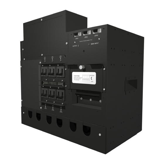
UPS Input / Output Circuit Breakers The Liebert GXT2-PP20KRT208 is equipped with six circuit breakers (three input breakers and three output breakers). During normal operation in the paralleling system, input/output circuit breakers are in the On position. When installing or removing a UPS, the corresponding breakers should be switched to the Off position. -
Page 12: Parallel Communication Port
Parallel Communication Port The Liebert GXT2-PP20KRT208 parallel POD has three 15-pin parallel communication ports on the upper right of the parallel POD. Several signals are provided on this port to communicate with each UPS. Use the parallel communication cables for the connection between the parallel POD and each UPS. -
Page 13: What' Included
’ NCLUDED The Liebert GXT2-PP20KRT208 is shipped with: • User Manual: 1 • Cover Plate for Main Terminal Block: 1 • Cover Plate for Parallel Communication Cable Connectors: 1 • Edge Guards: 6 • M6 Clips: 8 • Fixed Rack-Mounting Brackets: 4 •... -
Page 14: What You Need
What You Need You will need the following tools for assembly of the parallel system connections. • 3/8" slotted screwdriver • Phillip #1 screwdriver • Phillip #2 screwdriver • 10mm hex driver • 5mm hex driver • 3/16" hex wrench •... -
Page 15: Installation
Liebert representative. Mount the Liebert GXT2-PP20KRT208 in a Rack or on a Wall The Liebert GXT2-PP20KRT208 may be mounted either in a rack or on a wall. When installing the Liebert GXT2-PP20KRT208, use the factory-supplied fixed brackets. Position the four fixed brackets at the screw holes—front, middle or rearmost—on either side of the Liebert GXT2-PP20KRT208 that best fits the installation location desired and attach with included screws. -
Page 16: Mount The Liebert Gxt2-Pp20Krt208 On A Wall
3. Put the field-supplied wall inserts into the holes. 4. Hold the parallel POD against the wall, aligned with the mounting holes and use field-supplied screws to attach the unit to the wall (see Figure 10). Figure 10 Mount the Liebert GXT2-PP20KRT208 on a wall Installation... -
Page 17: Paralleling System Connections
Paralleling System Connections The Liebert GXT2-PP20KRT208 is shipped with the input and output slots for UPS and the optional output power distribution section covered. Installation of the paralleling system requires: parallel power cables, fixed plates and cable clamps. These are included in Liebert GXT2-20KPC-6 kit (see Figure 7). - Page 18 If the Liebert GXT2-10000RT-208 UPS was a stand-alone unit but now will be part of a paral- lel system, remove the input and output cables from the rear terminal block and cover the ter- minal block with the original conduit box. 10.
-
Page 19: Table 1 Electrical Requirements
Main Input and Output Terminal Block Connections Conduit entry holes are provided on the front top of the removable cover plate for the parallel POD. Input and output wiring should be run in separate conduit. See the following requirements and label to connect the wires. -
Page 20: Add An Output Power Distribution Module-Optional
Before beginning to install the optional output distribution module, make sure the paralleling system and all connected UPSs are completely powered off. To add an optional output distribution module to the Liebert GXT2-PP20KRT208: 1. Disconnect and secure utility power from the parallel POD and completely power Off all connected UPSs. -
Page 21: Parallel Pod Main Electrical Connection-Must Be Installed
Parallel POD Main Electrical Connection—Must Be Installed Electrical connections are made through a removable conduit box that attaches to the top of the paral- lel POD. A branch breaker is required for short circuit or overcurrent protection. The installer must provide a 120A (@ 208V to 240V) branch circuit breaker. -
Page 22: Initial Startup And Electrical Checks
NITIAL TARTUP AND This section includes the procedures on how to install the paralleling system for the first time and how to perform initial system checks of each UPS individually before connecting them in parallel. NOTICE Miswiring power to the input terminal block (L1-L2-N-G) may damage the UPS. For the initial installation, perform the following: 1. -
Page 23: Configuration
ONFIGURATION The Liebert GXT2-PP20KRT208 parallel POD allows connecting a maximum of three UPSs in paral- lel. See the following table for the maximum output power. Table 2 Maximum output power from paralleled UPSs Method Paralleling for Capacity Paralleling for Capacity... -
Page 24: Operation
PERATION Operating Modes 8.1.1 Online Mode NOTICE Verify the operation of each UPS as detailed in 6.0 - Initial Startup and Electrical Checks before powering On the parallel system as detailed below. To power On the paralleling system: 1. Connect all parallel power cables and parallel communication cables between the UPSs and parallel POD. -
Page 25: Bypass Mode
8.1.2 Bypass Mode WARNING Risk of electric shock. Can cause equipment damage, injury or death. Lethal voltages may exist within the UPS and parallel POD as long as the UPS is connected. Do not open the maintenance bypass breaker cover unless the operating procedure instructs you to do so or conditions require it. -
Page 26: Output Off Mode
8.1.3 Output Off Mode To transfer the paralleling system to Output Off Mode: 1. Make sure that each UPS is in Bypass Mode. If a UPS is not in Bypass Mode, press the UPS’ Off button once (see 8.1.2 - Bypass Mode). 2. -
Page 27: Add A Single Ups To The Online Paralleling System
Add a Single UPS to the Online Paralleling System 1. Make sure that breakers on the UPS to be added and the corresponding breakers on the parallel POD are in the Off position. 2. Connect the parallel power cables between the UPS and the parallel POD. 3. -
Page 28: Replacing A Faulty Power Module Or Ups Internal Battery
Replacing a Faulty Power Module or UPS Internal Battery 1. Press the UPS’ Off button twice within four seconds to turn off the UPS. The UPS will transfer to Output Off Mode. 2. Turn Off the input and output breakers on the UPS and the corresponding input and output breakers on the parallel POD. -
Page 29: Battery Low Voltage-Battery Mode
Battery Low Voltage—Battery Mode See the following conditions when the battery low voltage is detected in the paralleling system. • If one UPS battery is running low, it will transfer to Output Off Mode. The other UPSs continue to supply power to the load. •... -
Page 30: Communication
OMMUNICATION Communication Interface The Liebert GXT2-PP20KRT208 parallel POD has three communication connectors for communica- tion between the UPSs. These connectors must not be used for any other monitoring applications. Each connected Liebert GXT2-10000RT208 UPS can be monitored as described in 2.4 - Liebert ™... -
Page 31: Figure 15 Calculating Total Load Per Ups
Figure 15 Calculating total load per UPS 2 UPSes Connected to a Parallel Pod UPS1 UPS2 I/P O/P Input Maintenance Breaker Table 3 Calculating total load, 20kVA example 20kVA Load, Full Load of Parallel Pod 2 UPSs Connected to Parallel POD UPS 1 UPS 2 L1-N... -
Page 32: Ups Configuration Settings
UPS Configuration Settings Refer to the Liebert GXT2-10000RT208 user manual, SL-23444, for additional information on using the UPS Configuration Program. When the configuration program is used with any of the connected Liebert GXT2-10000RT208 UPSs, options selected are changed in all operational UPSs connected to the parallel POD with the parallel communication cable. -
Page 33: Table 5 Parallel Pod Specifications
Shipping, W x D x H in. (mm) Weight, lb (kg) Shipping Liebert GXT2-PP20KRT208 20,000VA / 16,000W at 120/208 or 120/240 VAC 16.94 x 9.85 x 16.61 (430 x 250 x 422) 23.05 x 16.74 x 19.38 (585 x 425 x 492) -
Page 34: Table 7 Optional Output Distribution Specifications-Pd-201
Table 7 Optional output distribution specifications—PD-201 Model Number Dimensions, in (mm) Shipping W x D x H in. (mm) Weight, lb (kg) Unit Shipping Electrical Specifications Amp Rating Input Power Connections Output Power Connection L1-L2-G L1-N-G L2-N-G Table 8 Optional output distribution specifications—PD-202 Model Number Dimensions, in (mm) Shipping, W x D x H in. - Page 36 Embedded Computing Connectivity Embedded Power DC Power Monitoring Business-Critical Continuity, Emerson Network Power and the Emerson Network Power logo are trademarks and service marks of Emerson Electric Co. ©2008 Emerson Electric Co. Technical Support / Service Liebert.monitoring@emerson.com Outside the US: 614-841-6755 upstech@emersonnetworkpower.com...
Need help?
Do you have a question about the GXT2-PP20KRT208 and is the answer not in the manual?
Questions and answers