
Summary of Contents for Maxon WL7-vers. C
- Page 1 INSTALLATION INSTRUCTIONS WHEELCHAIR LIFT MODEL NO. • WL7-vers. C • WL7-vers. C-1K DOT-Public Use Lift PATENTS PENDING FOR INSIDE VEHICLE INSTALLATION ONLY MP-06-09 REV. A © MAXON Lift Corp. 2009 APRIL 2009...
- Page 2 PATENTS PENDING...
- Page 3 THIS PAGE INTENTIONALLY LEFT BLANK PATENTS PENDING...
-
Page 4: Table Of Contents
TABLE OF CONTENTS INTRODUCTION ........................6 SAFETY SUMMARY ......................6 VEHICLE REQUIREMENTS ....................8 LIGHTING ..........................9 WHEELCHAIR DOOR DIMENSIONS ................. 10 LIFT DIMENSIONS ......................11 LIFT COMPONENTS & TERMINOLOGY ................14 DECALS AND DECAL PLACEMENT .................. 16 DECALS FOR WL7-vers. C ....................17 DECALS FOR WL7-vers. - Page 5 OUTBOARD ROLLSTOP TIME ADJUSTMENT (IF REQUIRED) ........50 FLOOR POSITION ADJUSTMENT (MANDATORY) ............52 SYSTEM DIAGRAMS ......................57 HYDRAULIC SYSTEM DIAGRAM ..................57 ELECTRICAL SYSTEM DIAGRAM ..................58 COMPLETED LIFT INSTALLATION CHECKLIST ............. 59 PATENTS PENDING...
-
Page 6: Introduction
INTRODUCTION This manual contains instructions for installing the MAXON MOBILITY Wheelchair Lift in a transit vehicle. Please follow these instructions carefully and call us immediately if you need assistance with the installation. Do not take shortcuts, skip over installation steps, or modify the Lift. - Page 7 1. Read and understand the instructions in this Installation Manual before installing Lift. 2. Before operating the Lift, read and understand the operating instructions contained in the Operator’s Manual. 3. Comply with all WARNING and instruction decals attached to both the Lift and the ve- hicle.
-
Page 8: Vehicle Requirements
VEHICLE REQUIREMENTS The minimum vehicle requirements for installing the WL7 Wheelchair Lift are described below. Installing the Lift in accordance with the vehicle requirements and the instructions in this manual will result in an installation that is compliant with Federal Motor Vehicle Safety Standard (FMVSS) 403 and FMVSS 404. -
Page 9: Lighting
ELECTRICAL POWER Vehicle must have a 12 volt dc electrical system capable of supplying 65 amperes of electrical power to the Lift for each operating cycle. SAFETY INTERLOCK SYSTEM Vehicle must have an FMVSS 403 compliant, onboard Safety Interlock System that interfaces with the Wheel- chair Lift interlock signal. -
Page 10: Wheelchair Door Dimensions
VEHICLE REQUIREMENTS - Continued WHEELCHAIR DOOR DIMENSIONS WHEELCHAIR DOOR DIMENSIONS ON TYPICAL VEHICLE WITH SIDE DOOR (SEE TABLE 10-1) FIG. 10-1 WHEELCHAIR WHEELCHAIR MODEL DOOR WIDTH DOOR HEIGHT DESCRIPTIONS (MINIMUM) (MINIMUM) 30” WIDE PLATFORM RH PUMP 39” 30” WIDE PLATFORM LH PUMP 33”... -
Page 11: Lift Dimensions
LIFT DIMENSIONS 18.9” 13.3” 2.9” 55.13” 1.4” 0.5” 39” 25” 4.75” 18-3/4” FRONT VIEW OF STOWED LIFT SIDE VIEW OF STOWED LIFT (LH PUMP MODEL SHOWN) (LH PUMP MODEL SHOWN) (SEE TABLE 11-1) FIG. 11-1 FIG. 11-2 OVERALL LIFT MODEL LIFT WIDTH AT LIFT WIDTH AT LIFT WIDTH AT... - Page 12 VEHICLE REQUIREMENTS - Continued WHEELCHAIR DOOR 0.75” (MIN.) 18-3/4” (APPROX.) 48”(MAX.) WHEELCHAIR DOOR CLEARANCE & FLOOR HEIGHT ON TYPICAL VEHICLE WITH SIDE DOOR FIG. 12-1 PATENTS PENDING...
- Page 13 3.75” (48” FLOOR LEVEL - REF) 6.75” (46” FLOOR LEVEL - REF) 8.75” (44” FLOOR LEVEL - REF) 10.25” (42” FLOOR LEVEL - REF) BASE PLATE OUTBOARD EDGE (REF) TYPICAL VEHICLE REAR BUMPER (VAN GND LVL) (BUS GND LVL) (BUS GND LVL) BODY CLEARANCE POINTS: 32”, 40”, 42”, 46”...
-
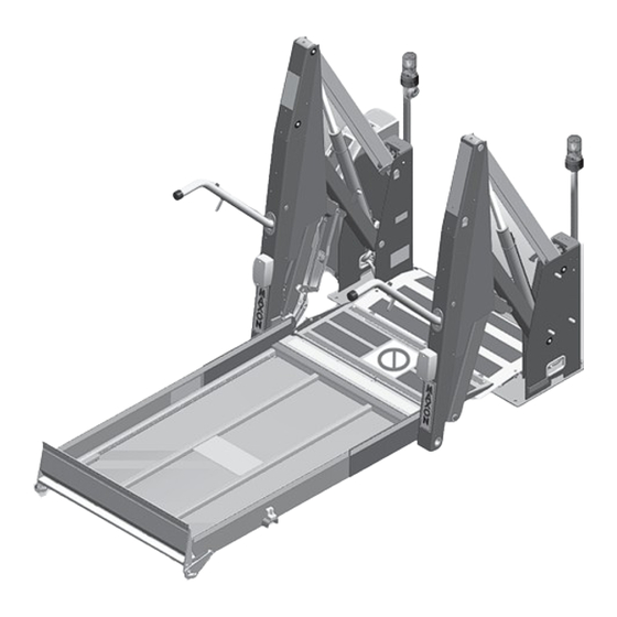
Page 14: Lift Components & Terminology
LIFT COMPONENTS & TERMINOLOGY INBOARD RIGHT LEFT OUTBOARD LIFT COMPONENTS (SEE TABLE 13-1) FIG. 14-1 PATENTS PENDING... - Page 15 ITEM NAME DESCRIPTION THRESHOLD PLATE Component that bridges the entry way, through the Lift, into the vehicle. Detects if that portion of Lift is occupied during “UP/DOWN” operation between vehicle fl oor and the ground. OUTBOARD ROLLSTOP Barrier to prevent the wheelchair from rolling off of the platform.
-
Page 16: Decals And Decal Placement
DECALS AND DECAL PLACEMENT DECAL ”D” DECAL “O” DECAL “K” DECAL “A” DECAL “B” DECAL “F” DECAL “L” DECAL “M” DECAL “I” DECAL“J” DECAL“N” DECAL “C” DECAL “E” DECAL“N” DECAL “H” FIG. 16-1 All WARNING, CAUTION, and OPERATION de- cals provided with Wheelchair Lift must always be in place on the Lift and vehicle (see FIG. -
Page 17: Decals For Wl7-Vers. C
DECALS FOR WL7-vers. C DECAL SET P/N 268302-01 FIG. 17-1 PATENTS PENDING... -
Page 18: Decals For Wl7-Vers. C-1K
DECALS AND DECAL PLACEMENT - Continued DECALS FOR WL7-vers. C-1K DECAL SET P/N 268302-03 FIG. 18-1 PATENTS PENDING... -
Page 19: Serial Plate & Controller
SERIAL PLATE & CONTROLLER CONTROLLER OVERLAY P/N 2667630-01 FIG. 19-1 SERIAL PLATE P/N 905246-8 FIG. 19-2 PATENTS PENDING... -
Page 20: Anti-Slip & Safety Striping
ANTI-SLIP & SAFETY STRIPING (30” WIDE PLATFORM) YELLOW TAPE (BOTTOM-ROLLSTOP) P/N 905293-17 ANTI-SLIP TAPE (ROLLSTOP) P/N 096020-13 ANTI-SLIP TAPE P/N 096024-10 ANTI-SLIP TAPE P/N 096020-10 ANTI-SLIP TAPE P/N 096013-10 YELLOW TAPE (OUTBOARD) P/N 905293-11 YELLOW TAPE (OUTBOARD) P/N 905293-14 YELLOW TAPE (INBOARD) ANTI-SLIP TAPE P/N 905293-16... - Page 21 ANTI-SLIP & SAFETY STRIPING - Continued (33” WIDE PLATFORM) YELLOW TAPE (BOTTOM-ROLLSTOP) P/N 905293-18 ANTI-SLIP TAPE (ROLLSTOP) P/N 096020-14 ANTI-SLIP TAPE P/N 096024-11 ANTI-SLIP TAPE P/N 096020-11 ANTI-SLIP TAPE P/N 096013-11 YELLOW TAPE (OUTBOARD) P/N 905293-11 YELLOW TAPE (OUTBOARD) P/N 905293-14 YELLOW TAPE (INBOARD) ANTI-SLIP TAPE...
- Page 22 ANTI-SLIP & SAFETY STRIPING - Continued (34” WIDE PLATFORM) YELLOW TAPE (BOTTOM-ROLLSTOP) P/N 905293-18 ANTI-SLIP TAPE (ROLLSTOP) P/N 096020-15 ANTI-SLIP TAPE P/N 096024-12 ANTI-SLIP TAPE P/N 096020-12 ANTI-SLIP TAPE P/N 096013-11 YELLOW TAPE (OUTBOARD) P/N 905293-11 YELLOW TAPE (OUTBOARD) P/N 905293-14 YELLOW TAPE (INBOARD) ANTI-SLIP TAPE...
-
Page 23: Lift Installation
LIFT INSTALLATION INSTALLATION KITS An installation kit is required to install Lift on your vehicle. Refer to the instruction sheet, included with the installation kit, for specifi c instructions to fi t the Lift to your vehicle. PREPARING AND POSITIONING THE LIFT 1. - Page 24 PREPARING AND POSITIONING THE LIFT - Continued NOTE: You may use a template instead of the Lift for positioning the Lift on vehicle. To use a template, refer to USING TEM PLATE TO POSITION LIFT section in this Installation Manual. WHEELCHAIR 5.
-
Page 25: Using Template To Position Lift
USING TEMPLATE TO POSITION LIFT 1. Fabricate template for base plate hole pattern according to the dimensions shown in FIGS. 25-1, 25-2, 26-1 and 26-2. Use a suitable material that maintains correct shape and dimensions. BASE PLATE HOLE PATTERN FOR LIFTS WITH 33”... - Page 26 USING TEMPLATE TO POSITION LIFT - Continued BASE PLATE HOLE PATTERN FOR LIFTS WITH 30” WIDE PLATFORM & LH PUMP FIG. 26-1 BASE PLATE HOLE PATTERN FOR LIFTS WITH 30” WIDE PLATFORM & RH PUMP FIG. 26-2 PATENTS PENDING...
- Page 27 CAUTION For vehicles with 48” fl oor height: If the front edge of Lift base plate is moved more than 3.75” (5” from outside of body, as shown in FIG. 11-1) away from the inside of the wheelchair door, lower Lift arms can hit vehicle body before platform reaches the ground.
-
Page 28: Mounting The Lift
MOUNTING THE LIFT NOTE: MAXON recommends using all 10 carriage screws (Kit items) to bolt Lift to vehicle. A minimum of 8 screws or bolts and use of holes 1, 2, 3, 4 & 9 are required for correct installation. Also, the 3 front holes should be selected to give a symmetrical bolt pattern (i.e. -
Page 29: Install Main Circuit Breaker
INSTALL MAIN CIRCUIT BREAKER WARNING To prevent personal injury and equipment damage, make sure power is discon- nected from Lift when installing electrical parts. NOTE: Apply dielectric grease on all electrical connections after all electrical cables are connected. 1. Attach 90 amp main circuit breaker (Kit item) to vehicle so power cable (Kit item) is within reach of the battery, as follows. - Page 30 INSTALL MAIN CIRCUIT BREAKER - Continued 2. Connect one end of power cable to 90 amp main circuit breaker (FIG. 30-1). Do not connect battery end until instructed to connect the battery. 1/4” FLAT WASHER (2 PLACES) BATTERY 1/4”-20 LOCK NUT (2 PLACES) 2 AWG POWER CABLE (SHORT CABLE)
-
Page 31: Route/Connect Cables & Hand Pendant
ROUTE/CONNECT CABLES & HAND PENDANT CAUTION Never route an energized wire. Make sure the battery is disconnected. Always route electrical wire clear of any moving parts, brake lines, sharp edges, and ex- haust systems. Never route power cable next to a wiring harness on the vehicle. Do not loop excess cable. - Page 32 ROUTE/CONNECT CABLES & HAND PENDANT - Continued POWER 4. Cut any excess wire from long power cable. INPUT Strip 1/2” insulation from the cut end and BRACKET install 2 GA terminal lug and shrink tubing. 2 GA Next, insert the power cable through the TERMINAL protective cover (FIG.
- Page 33 7. Uncoil the ground cable from the bottom of the pump cover. Route the ground cable on the Lift through grommet in vehicle fl oor (FIG. 33-1A & 33-1B). GROUND CABLE GROMMET GROUND CABLE ROUTED FROM LIFT NOTE: Clean the ground cable FIG.
- Page 34 ROUTE/CONNECT CABLES & HAND PENDANT - Continued CAUTION To prevent vehicle access door from pinching and damaging the hand pendant cable, secure cable away from the door frame. Also, be sure that the hand pendant cable does not interfere with or bind against moving parts. 10.
- Page 35 11. Find accessible place on vehicle wall or wheelchair door (near Lift) to place the hand pendant hanger and cable hook (FIG. 35-1). HAND PENDANT & HANGER CABLE HOOK PUMP COVER TYPICAL LOCATION (INSIDE VEHICLE) FOR STOWING HAND PENDANT FIG. 35-1 PATENTS PENDING...
- Page 36 ROUTE/CONNECT CABLES & HAND PENDANT - Continued 12. Place decals (from Parts Box) on the vehicle, near the hand pendant (typical place- ment shown in FIG. 36-1). Make sure decals are visible to operator when Lift is being operated. HAND PENDANT & HANGER MOUNTING DECAL “J”...
- Page 37 13. Connect short power cable to vehicle POSITIVE (+) BATTERY SHORT POWER TERMINAL CABLE battery as follows. Remove nut from BOLT positive (+) battery terminal connec- tor (FIG. 37-1). Connect the power cable. Reinstall nut. CONNECTING POWER TO LIFT (TYPICAL) FIG.
- Page 38 ROUTE/CONNECT CABLES & HAND PENDANT - Continued 15. Press the UNFOLD button on hand pendant to unfold Lift (FIG. 38- 1). Platform lights will turn on when PLATFORM LIGHT platform is at fl oor level. (2 PLACES) LIFT AT FLOOR LEVEL FIG.
-
Page 39: Checking Hydraulic Fluid Level
CHECKING HYDRAULIC FLUID LEVEL CAUTION Keep dirt, water and other contaminants from entering the hydraulic sys- tem. Before opening the hydraulic fl uid reservoir fi ller cap, drain plug and hydraulic lines, wipe off contaminants that can get in the openings. Also, protect the openings from accidental contamination. - Page 40 CHECKING HYDRAULIC FLUID LEVEL - Continued 3. Pull out fi ller cap (FIG. 40-1). Fill the reservoir with hydraulic fl uid (TABLE 40-1) to level shown in FIG. 40-1. Reinstall fi ller cap (FIG. 40-1). RECOMMENDED HYDRAULIC FLUID FILLER BRAND PART NUMBER ROSEMEAD THS FLUID 17111...
- Page 41 THIS PAGE INTENTIONALLY LEFT BLANK PATENTS PENDING...
-
Page 42: Adjustments
ADJUSTMENTS MAT SWITCH ADJUSTMENT (IF REQUIRED) 1. Make sure power switch POWER SWITCH (FIG. 42-1A) is turned on. Lower Lift to the ground (FIG. 42- 1A). 5/8” HEIGHT MEASUREMENT LIFT AT GROUND LEVEL (RH SIDE SHOWN) FIG. 42-1A FIG. 42-1B 2. - Page 43 4. Turn the MAT switch adjustment screw THRESHOLD WARNING BEACON (FIGS. 43-1B and 43-2) clockwise until threshold warning alarm and beacons acti- THRESHOLD WARNING ALARM vate (FIG. 43-1A). Then, turn adjustment screw counter-clockwise (FIG. 43-2) ap- proximately 1-1/2 turn. Warning alarm and beacons should turn off.
-
Page 44: Platform Tilt Adjustment (Mandatory)
PLATFORM TILT ADJUSTMENT (MANDATORY) NOTE: The platform tilt adjustment is important for operation of the outboard roll- stop and for keeping platform level when it reaches the ground. Vehicle fl oor height, Lift and stiffness of the vehicle suspension may change the angle of platform on the ground. - Page 45 OUTBOARD ROLLSTOP 4. Manually lower the inboard ADJUSTMENT (REF) rollstop for access to the ad- SCREW justment screws (FIG. 45-1). To ensure proper leveling, turn platform tilt adjustment screws (FIG. 45-1) an equal amount on both sides of platform. Turn adjustment screws clockwise (FIG.
-
Page 46: Inboard Switch Adjustment (If Required)
INBOARD SWITCH ADJUSTMENT (IF REQUIRED) NOTE: Do this procedure if the Controller reads “IBRS SW” when Inboard Rollstop is locked in the up position. The adjustment is done correctly if the Controller does not read “IBRS SW” when the Inboard Rollstop is locked in the up position. POWER 1. - Page 47 4. Push the inboard rollstop back against the lock as if a wheel- chair is pushing on the rollstop FIG. 47-1). PUSH IBRS AGAINST LOCK IBRS PLATFORM BELOW FLOOR LEVEL, 5. On the inboard rollstop switch, WITH IBRS UP (LH SIDE SHOWN) loosen screws (1) and (2) one-half FIG.
-
Page 48: Changing Controller To Spanish Or English (If Required)
CHANGING CONTROLLER TO SPANISH OR ENGLISH (IF REQUIRED) NOTE: The power switch on the Lift FOLD must be turned OFF before entering SETUP. 1. Turn power switch OFF (FIG. 48-2). HAND PENDANT: ENTERING SETUP FIG. 48-1 POWER SWITCH CONTROLLER (REF) 2. - Page 49 3. Push and release the FOLD FOLD switch (FIG. 49-1). Con- troller should be in the LANGUAGE mode (FIG. 49-2). HAND PENDANT: CHANGING SETUP MODE FIG. 49-1 LANGUAGE: ENGLISH CONTROLLER: LANGUAGE NOTE: After you exit SETUP, the con- SETTING (ENGLISH OR SPANISH) troller readings will be displayed FIG.
-
Page 50: Outboard Rollstop Time Adjustment (If Required)
OUTBOARD ROLLSTOP TIME ADJUSTMENT (IF REQUIRED) NOTE: Call MAXON Technical Service FOLD before doing this adjustment. NOTE: The power switch on the Lift must be turned OFF before entering SETUP. 1. Turn power switch OFF (FIG. 50-2). HAND PENDANT: ENTERING SETUP FIG. - Page 51 3. Push and release the FOLD switch (FIG. 51-1) to ac- FOLD cess the OUTBD TIME set- ting (FIG. 51-2). HAND PENDANT: CHANGING SETUP MODE FIG. 51-1 NOTE: A larger number for the OUTBD TIME setting allows more time OUTBD TIME: 0 for the controller to sense the outboard rollstop is closed.
-
Page 52: Floor Position Adjustment (Mandatory)
FLOOR POSITION ADJUSTMENT (MANDATORY) NOTE: Do the following procedure to ensure the inboard rollstop rests on threshold plate and lines up approximately with edge of base plate. 1. Unfold the platform until the lights illuminate at fl oor level or raise the platform to fl... - Page 53 3. If the inboard rollstop does not line up THRESHOLD EDGE OF PLATE INBOARD correctly with the edge of the base plate ROLLSTOP (FIGS. 53-1 and 53-2), go to IN- STRUCTION 4. EDGE OF BASE PLATE INBOARD ROLLSTOP OVERLAPS EDGE OF BASE PLATE FIG.
- Page 54 FLOOR POSITION ADJUSTMENT - Continued 5. Enter SETUP by holding both FOLD the UP and FOLD switches on the hand pendant (FIG. 54-1) and turning the power switch ON at the same time (FIG. 53- 3). Controller will read SETUP (FIG.
- Page 55 7. To decrease overlap, push the UP switch from 1 to 5 times (FIG. 55-1). The FLOOR POS number displayed on DOWN the controller (FIG. 55-2) will increase by 1 each time you push the UP but- ton. To close the gap, push the DOWN switch from 1 to 5 times (FIG.
- Page 56 FLOOR POSITION ADJUSTMENT - Continued 9. Lower the platform until the inboard rollstop is in the up and locked posi- tion. Next, raise the platform to fl oor INBOARD level (FIG. 56-1A). Verify that the ROLLSTOP THRESHOLD inboard rollstop lines up with the PLATE edge of the base plate as shown in FIG 56-1B.
-
Page 57: System Diagrams
SYSTEM DIAGRAMS HYDRAULIC SYSTEM DIAGRAM FLOW CONTROL FLOW CONTROL VALVE - .5 GPM VALVE - .5 GPM PRESSURE TRANSDUCER CYLINDER CYLINDER PRESSURE PORT PRESSURE PORT MANUAL S.V.1 RELEASE VALVE .018 DIA. S.V.2 MANUAL RETURN BACK-UP PUMP RETURN GEAR FILLER - PUMP BREATHER R.V. -
Page 58: Electrical System Diagram
SYSTEM DIAGRAMS - Continued ELECTRICAL SYSTEM DIAGRAM FIG. 58-1 PATENTS PENDING... -
Page 59: Completed Lift Installation Checklist
COMPLETED LIFT INSTALLATION CHECKLIST 1. Make sure vehicle is still parked on level ground. If vehicle is equipped with a parking brake, set the parking brake. If equipped with locking service brake, set the service brake and make sure vehicle is in park or neutral. - Page 60 8. Make sure platform lowers all the way to the ground and platform lights are illuminated while platform is lowering. Press DOWN button on the hand pendant to lower platform to the ground. As the plat- form is lowering: • Controller must display DOWN •...
Need help?
Do you have a question about the WL7-vers. C and is the answer not in the manual?
Questions and answers