
Related Manuals for Pro Co Sound Momentum MO8

Summary of Contents for Pro Co Sound Momentum MO8
- Page 1 Eight Channel Analog Output Manual Pro Co Sound, Inc. 225 Parsons Street | Kalamazoo, MI 49007 1-888-253-7360 | www.procomomentum.com...
-
Page 2: Warranty
If the problem cannot be resolved remotely, Pro Co Sound may, at its discretion, advance the replacement of the defective unit(s) and at that time provide a Return Authorization number by which the defective unit(s) can be returned for credit or repair. Momentum mo8 Manual Revision Date: 5/28/2008... -
Page 3: Table Of Contents
Fiber Connection Network Confi guration Setup Network Clock Sync Using the Control Panel Setting Device Start Channel IP Address Sample Rate Chapter 3: Control Panel Functions F1 and F2 Functions Description of Functions Chapter 4: mo8 Specifi cations Momentum mo8 Manual... -
Page 4: Safety Precautions
8. Do not defeat the safety purposes of the polarized or grounding type plugs. 9. Do not use the Momentum power supply for any purpose other than stated in this manual. 10. Only use Pro Co recommended accessories with any Momentum device. Momentum mo8 Manual... -
Page 5: Welcome
You should fi nd the following in the carton: 1 x mo8 2 x Stage Boots (optional) 2 x Rack Ears 1 x One Spot Power Supply NOTE: Stage boots may be requested, for no additional charge at time of order. Momentum mo8 Manual... -
Page 6: Chapter 1: Overview
Fiber optic option Crestron or AMX • Firmware upgradable in fi eld • Phoenix connector and DB25 options • 8 balanced analog outputs available for permanent installations or • Selectable 48K or 96K sampling easy passive splits Momentum mo8 Manual... -
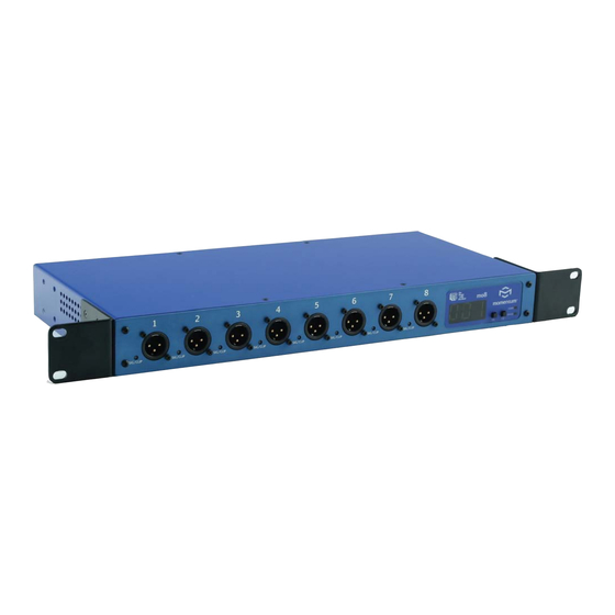
Page 7: The Mo8
2-Button Control Panel Description 1 Signal/Clip LED Green = -40dB F.S. or above; Red= -3dB F.S. or above 2 Status LED Green = Network connected; Red = Network fault 3 Power LED Green = Digital power OK Momentum mo8 Manual... -
Page 8: Rear Panel
Rear Panel with Contractor Panel The optional contractor panel allows input analog connection from the rear of the device. These inputs are paralleled to the XLR connectors on the front of the mo8. Momentum mo8 Manual... -
Page 9: Chapter 2: Connection And Startup
Use a standard Gigabit IEEE 802.3af PoE network switch and power up through the Ethernet cable. The POE switch must be capable of 15Watts per Ethernet port. Ethernet port One Spot or MUPS power supply ports Momentum mo8 Manual... -
Page 10: Network Wiring
IEEE 802.3z Gigabit Ethernet compliant. The following are performance based on the cable type: 220 meter distance use 62.5/125um MMF 160MHz Km Cable 275 meter distance use 62.5/125um MMF 200MHz Km Cable 500 meter distance use 50/125um MMF 400MHz Km Cable 550 meter distance use 50/125um MMF 500MHz Km Cable Momentum mo8 Manual... -
Page 11: Network Confi Guration
Direct Copper Connection 275 Meters using 62.5/125um MMF 200Mhz CAT5E or CAT6 550 Meters using 50/125um MMF 500Mhz No crossover required 100 Meters Cross Fiber Rx/Tx mo8 Output Optionally, Fiber and Copper may both be connected for redundancy. Momentum mo8 Manual... -
Page 12: Connection And Setup
Chn=033 Adr=012 set the Ethernet port that is connected mo8 Output to your control PC to multicast filtering. Chn=041 Adr=013 Multicast MAC 01:15:AB:C6:00:00 mi8 Input Chn=049 Adr=007 (See Network Design White Papers) Managed Control Device Ethernet Switch Momentum mo8 Manual... - Page 13 Adr=021 mo8 Output Chn=049 Adr=022 Managed mo8 Output mo8 Outpu Chn=057 Adr=023 Chn=057 A Ethernet Switch Note: Up to 256 inputs channels, and unlimited outputs or DSPs can be added anywhere on the network using this method. Momentum mo8 Manual...
-
Page 14: Setup
Network connections have been found and the network is run- ning. RED indicates there are one of two problems; 1) An Ethernet link is not established or is not connected. 2) The audio sync packet (channel 1) is not found. Momentum mo8 Manual... -
Page 15: Setting Device
It is best practice to keep the input unit’s IP address sequential with its channel. In other words, Chn 001-008 would be Adr 001 and Chn 009-016 would be Adr 002 and so on. Sample Rate ALL DEVICES in the network must be set at a sample rate of either 48k or 96k. Momentum mo8 Manual... -
Page 16: Chapter 3: Control Panel Functions
The fl ow chart below displays each of the controlling F1 and F2 . Descriptions of each functions follow in a guide on pages 16 and 17. [Adr] [rou] [Vol] [Chn] [Adr] [Sr] [Clr] Address Route Gain Start Sample Clear Channel Address Rate Settings Display Momentum mo8 Manual... -
Page 17: Description Of Functions
Tap F1 to decrease value. Tap F2 in increase value. Press and hold F1 and F2 to return to channel selection. On completing channel selection, press F1 & F2 to exit or allow display to time out. Momentum mo8 Manual... -
Page 18: Sample Rate
This function sets attenuation to zero. Toggle F2 to select Clr. Tap F1 to activate Clr. (It will flash) Press and hold F1 and F2 simultaneously to execute and save the change. Exit by allowing display to time out. Momentum mo8 Manual... -
Page 19: Chapter 4: Mo8 Specifi Cations
Up to 256 total active system inputs at 48K or 96K sampling Onboard memory and programming 0.315 ms A/A latency 96K sampling (no DSP) 0.630 ms A/A latency 48K sampling (no DSP) 1.00 ms A/A latency 48K sampling (with DSP) Open UDP Ethernet communication for 3rd party control Momentum mo8 Manual...
Need help?
Do you have a question about the Momentum MO8 and is the answer not in the manual?
Questions and answers