Table of Contents
Advertisement
®
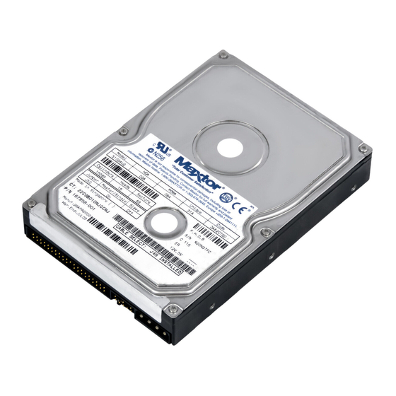
DiamondMax
Plus 40
54098U8, 53073U6, 52049U4,
51536U3, 51024U2
Part #1429/A
All material contained herein Copyright © 2000 Maxtor Corporation.
MaxFax™ is a trademark of Maxtor Corporation. DiamondMax
®
, Maxtor
®
®
and No Quibble
Service are registered trademarks of Maxtor Corporation.
Other brands or products are trademarks or registered trademarks of their
respective holders. Contents and specifications subject to change without
notice. All rights reserved.
Corporate Headquarters
510 Cottonwood Drive
Milpitas, California 95035
Tel: 408-432-1700
Fax: 408-432-4510
Research and Development Center
2190 Miller Drive
Longmont, Colorado 80501
Tel: 303-651-6000
Fax: 303-678-2165
Advertisement
Table of Contents

Related Manuals for Maxtor DIAMONDMAX PLUS 40 51024U2


Summary of Contents for Maxtor DIAMONDMAX PLUS 40 51024U2
- Page 1 ® DiamondMax Plus 40 54098U8, 53073U6, 52049U4, 51536U3, 51024U2 Part #1429/A All material contained herein Copyright © 2000 Maxtor Corporation. MaxFax™ is a trademark of Maxtor Corporation. DiamondMax ® , Maxtor ® ® and No Quibble Service are registered trademarks of Maxtor Corporation.
- Page 2 During handling, NEVER drop, jar, or bump a drive. 4 4 4 4 4 Once a drive is removed from the Maxtor shipping container, IMMEDIATELY secure the drive through its mounting holes within a chassis. Otherwise, store the drive on a padded, grounded, antistatic surface.
-
Page 3: Table Of Contents
Contents Section 1 Section 1 Section 1 — Introduction Introduction Introduction Introduction Section 1 Section 1 Introduction Maxtor Corporation 1 - 1 Products 1 - 1 Support 1 - 1 Manual Organization 1 - 1 Abbreviations 1 - 1 Conventions... - Page 4 DIAMONDMAX PLUS 40 PRODUCT MANUAL Section 3 Section 3 Section 3 — Product Specifications Section 3 Section 3 Product Specifications Product Specifications Product Specifications Product Specifications Models and Capacities 3 - 1 Drive Configuration 3 - 1 Performance Specifications 3 - 1 Physical Dimensions 3 - 2 Power Requirements...
- Page 5 DIAMONDMAX PLUS 40 PRODUCT MANUAL Section 5 Section 5 Section 5 Section 5 Section 5 — AT Interface Description AT Interface Description AT Interface Description AT Interface Description AT Interface Description Interface Connector 5 - 1 Pin Description Summary 5 - 1 Pin Description Table 5 - 2 PIO Timing...
- Page 6 DIAMONDMAX PLUS 40 PRODUCT MANUAL Write Verify Sector(s) 7 - 4 Write Sector Buffer 7 - 4 Write DMA 7 - 5 Write Multiple 7 - 5 Ultra DMA 7 - 5 Set Feature Commands 7 - 5 Set Features Mode 7 - 5 Power Mode Commands 7 - 7...
- Page 7 DIAMONDMAX PLUS 40 PRODUCT MANUAL Figures Figures Figures Figures Figures Figure Title Page 2 - 1 PCBA Jumper Location and Configuration 2 - 6 3 - 1 Outline and Mounting Dimensions 3 - 2 4 - 1 Multi-pack Shipping Container 4 - 2 4 - 2 Single-pack Shipping Container (Option A)
-
Page 8: Section 1 - Introduction Section 1 Introduction
Support Support Support No matter which capacity, all Maxtor hard drives are supported by our commitment to total customer ® satisfaction and our No Quibble Service guarantee. One call – or a visit to our home page on the Internet (http://www.maxtor.com) –... -
Page 9: Conventions
DIAMONDMAX PLUS 40 – INTRODUCTION Conventions Conventions Conventions Conventions Conventions If there is a conflict between text and tables, the table shall be accepted as being correct. Key Words Key Words Key Words Key Words Key Words The names of abbreviations, commands, fields and acronyms used as signal names are in all uppercase type (e.g., IDENTIFY DRIVE). -
Page 10: Section 2 - Product Description Product Description
Maxtor's latest advancements in electronic packaging and integration methods have lowered the drive's power consumption and increased its reliability. Advanced giant magneto-resistive read/write heads and a state-of-the-art head/disk assembly - using an integrated motor/spindle design - allow up to four disks in a 3.5-inch package. -
Page 11: Product Features
DiamondMax Plus 40 drives power-up in a translate mode: (*) The fields LZone (Landing Zone) and WPcom (Write Pre-comp) are not used by the Maxtor hard drive and the values may be either 0 or the values set by the BIOS. All capacities listed in the above table are based on 10 or one million bytes. -
Page 12: Defect Management Zone
PRODUCT DESCRIPTION The LBA is checked for violating the drive capacity. If it does not, the LBA is converted to physical drive cylinder, head and sector values. The physical address is then used to access or store the data on the disk and for other drive related operations. -
Page 13: Major Hda Components
Read/Write Heads and Media Read/Write Heads and Media Low mass, low force giant magneto-resistive read/write heads record data on 3.5-inch diameter disks. Maxtor uses a sputtered thin film medium on all disks for DiamondMax Plus 40 drives. Air Filtration System... -
Page 14: Subsystem Configuration
PRODUCT DESCRIPTION Subsystem Configuration Subsystem Configuration Subsystem Configuration Subsystem Configuration Subsystem Configuration Dual Drive Support Dual Drive Support Dual Drive Support Dual Drive Support Dual Drive Support Two drives may be accessed via a common interface cable, using the same range of I/O addresses. The drives are jumpered as device 0 or 1 (Master/Slave), and are selected by the drive select bit in the Device/Head register of the task file. -
Page 15: Models And Capacities
PRODUCT SPECIFICATIONS SECTION 3 Product Specifications Product Specifications Product Specifications Product Specifications Product Specifications Models and Capacities Models and Capacities Models and Capacities Models and Capacities Models and Capacities o i l l i b o i l Drive Configuration Drive Configuration Drive Configuration Drive Configuration... -
Page 16: Physical Dimensions
PRODUCT SPECIFICATIONS Physical Dimensions Physical Dimensions Physical Dimensions Physical Dimensions Physical Dimensions (maximum) i l l i i l l i i l l i o l i 1.028 max [26.1 mm max 6 x 6-32 1.638 ± .010 1.122 ± .020 .25 ±... -
Page 17: Power Requirements
EPA Energy Star Compliance EPA Energy Star Compliance EPA Energy Star Compliance EPA Energy Star Compliance Maxtor Corporation supports the goals of the U.S. Environmental Protection Agency’s Energy Star program to reduce the electrical power consumption of computer equipment. Environmental Limits Environmental Limits... -
Page 18: Shock And Vibration
Quality Acceptance Rate Quality Acceptance Rate < 1,000 DPPM The quality acceptance rate indicates the percentage of Maxtor products successfully installed by our customers, and/or the number of defective parts per million (DPPM) encountered during the entire installation process. Start/Stop Cycles... -
Page 19: Emc/Emi
Safety Regulatory Compliance Safety Regulatory Compliance All Maxtor hard drives comply with relevant product safety standards such as CE, CUL, TUV and UL rules and regulations. As delivered, Maxtor hard drives are designed for system integration before they are used. -
Page 20: Handling And Installation
Electro-Static Discharge (ESD) To avoid some of the problems associated with ESD, Maxtor advises that anyone handling a disk drive use a wrist strap with an attached wire connected to an earth ground. Failure to observe these precautions voids the product warranty. -
Page 21: Unpacking And Inspection
As they are removed, inspect drives for evidence of shipping damage or loose hardware. If a drive is damaged (and no container damage is evident), notify Maxtor immediately for drive disposition. Figure 4 - 1 Multi-pack Shipping Container 4 –... -
Page 22: Repacking
Single Pack Shipping Container (Option B) Repacking Repacking Repacking Repacking Repacking If a Maxtor drive requires return, repack it using Maxtor packing materials, including the antistatic bag. Physical Installation Physical Installation Physical Installation Physical Installation Physical Installation Recommended Mounting Configuration... -
Page 23: Before You Begin
Maxtor recommends that you make a backup copy of the files on any existing hard drives prior to installing the new drive. If required, this data may then be copied to the Maxtor hard drive after it has been installed in the computer. Refer to your computer user’s manual for detailed data backup instructions. -
Page 24: Install Hard Drive In Device Bay
Attach an IDE interface connector to J1 on the Maxtor drive. Attach a power connector to J2 on the Maxtor drive. This connector is keyed and will only fit one way. Check all other cable connections before you power up. -
Page 25: Interface Connector
AT INTERFACE DESCRIPTION SECTION 5 A A A A A T Interface Description T Interface Description T Interface Description T Interface Description T Interface Description Interface Connector Interface Connector Interface Connector Interface Connector Interface Connector All DiamondMax ® Plus 40 AT drives have a 40-pin ATA interface connector mounted on the PCBA. The drive may connect directly to the host;... -
Page 26: Pin Description Table
AT INTERFACE DESCRIPTION Pin Description Table Pin Description Table Pin Description Table Pin Description Table Pin Description Table 5 – 2... -
Page 27: Pio Timing
AT INTERFACE DESCRIPTION PIO Timing PIO Timing PIO Timing PIO Timing PIO Timing Figure 5 - 2 PIO Data Transfer To/From Device 5 – 3... -
Page 28: Dma Timing
AT INTERFACE DESCRIPTION DMA Timing DMA Timing DMA Timing DMA Timing DMA Timing Figure 5 - 3 Multi-word DMA Data Transfer 5 – 4... -
Page 29: Ultra Dma Timing Parameters
AT INTERFACE DESCRIPTION Ultra DMA Timing Ultra DMA Timing Ultra DMA Timing Ultra DMA Timing Ultra DMA Timing DMARQ (device) DMACK- (host) STOP (host) HDMARDY- (host) ZIORDY DSTROBE (device) DD(15:0) DA0, DA1, DA2, CS0-, CS1- Figure 5 - 4 Initiating an Ultra DMA Data In Burst 5 –... -
Page 30: Sustained Ultra Dma Data In Burst
AT INTERFACE DESCRIPTION 2CYC 2CYC DSTROBE at device DD(15:0) at device DSTROBE at host DD(15:0) at host Figure 5 - 5 Sustained Ultra DMA Data In Burst DMARQ (device) DMACK- (host) STOP (host) HDMARDY- (host) DSTROBE (device) DD(15:0) (device) Figure 5 - 6 Host Pausing an Ultra DMA Data In Burst 5 –... -
Page 31: Device Terminating An Ultra Dma Data In Burst
AT INTERFACE DESCRIPTION DMARQ (device) DMACK- (host) STOP (host) HDMARDY- (host) IORDYZ DSTROBE (device) DD(15:0) DA0, DA1, DA2, CS0-, CS1- Figure 5 - 7 Device Terminating an Ultra DMA Data In Burst DMARQ (device) DMACK- (host) STOP (host) HDMARDY- (host) IORDYZ DSTROBE (device) -
Page 32: Initiating An Ultra Dma Data Out Burst
AT INTERFACE DESCRIPTION DMARQ (device) DMACK- (host) STOP (host) ZIORDY DDMARDY- (device) HSTROBE (host) DD(15:0) (host) DA0, DA1, DA2, CS0-, CS1- Figure 5 - 9 Initiating an Ultra DMA Data Out Burst 2CYC 2CYC HSTROBE at host DD(15:0) at host HSTROBE at device DD(15:0) -
Page 33: Device Pausing An Ultra Dma Data Out Burst
AT INTERFACE DESCRIPTION DMARQ (device) DMACK- (host) STOP (host) DDMARDY- (device) HSTROBE (host) DD(15:0) (host) Figure 5 - 11 Device Pausing an Ultra DMA Data Out Burst DMARQ (device) DMACK- (host) STOP (host) IORDYZ DDMARDY- (device) HSTROBE (host) DD(15:0) (host) DA0, DA1, DA2, CS0-, CS1- Figure 5 - 12... -
Page 34: Device Terminating An Ultra Dma Data Out Burst
AT INTERFACE DESCRIPTION DMARQ (device) DMACK- (host) STOP (host) IORDYZ DDMARDY- (device) HSTROBE (host) DD(15:0) (host) DA0, DA1, DA2, CS0-, CS1- Figure 5 - 13 Device Terminating an Ultra DMA Data Out Burst 5 – 10... -
Page 35: Task File Registers
HOST SOFTWARE INTERFACE SECTION 6 Host Software Interface Host Software Interface Host Software Interface Host Software Interface Host Software Interface The host communicates with the drive through a set of controller registers accessed via the host’s I/O ports. These registers divide into two groups: the Task File, used for passing commands and command parameters and the Control/Diagnostic registers. -
Page 36: Sector Count Register
HOST SOFTWARE INTERFACE Sector Count Register Sector Count Register Sector Count Register Sector Count Register Sector Count Register Holds the number of sectors to be sent during a Read or Write command, and the number of sectors per track during a Format command. A value of zero in this register implies a transfer of 256 sectors. A multi- sector operation decrements the Sector Count register. -
Page 37: Command Register
HOST SOFTWARE INTERFACE Command Register Command Register Command Register Command Register Command Register Contains code for the command to be performed. Additional command information should be written to the task file before the Command register is loaded. When this register is written, the BUSY bit in the Status register sets, and interrupt request to the host clears;... -
Page 38: Summary
HOST SOFTWARE INTERFACE Summary Summary Summary Summary Summary 6 – 4... -
Page 39: Control Diagnostic Registers
HOST SOFTWARE INTERFACE Control Diagnostic Registers Control Diagnostic Registers Control Diagnostic Registers Control Diagnostic Registers Control Diagnostic Registers These I/O port addresses reference three Control/Diagnostic registers: Alternate Status Register Alternate Status Register Alternate Status Register Alternate Status Register Alternate Status Register Contains the same information as the Status register in the Task File. -
Page 40: Reset And Interrupt Handling
HOST SOFTWARE INTERFACE Reset and Interrupt Handling Reset and Interrupt Handling Reset and Interrupt Handling Reset and Interrupt Handling Reset and Interrupt Handling Reset Handling Reset Handling Reset Handling Reset Handling Reset Handling One of three different conditions may cause a reset: power on, hardware reset or software reset. All three cause the interface processor to initialize itself and the Task File registers of the interface. - Page 41 INTERFACE COMMANDS SECTION 7 Interface Commands Interface Commands Interface Commands Interface Commands Interface Commands The following section describes the commands (and any parameters necessary to execute them), as well as Status and Error register bits affected. Read Commands Read Commands Read Commands Read Commands Read Commands...
-
Page 42: Read Commands
INTERFACE COMMANDS Read Commands Read Commands Read Commands Read Commands Read Commands Read Sector(s) Read Sector(s) Read Sector(s) Read Sector(s) Read Sector(s) Reads from 1 to 256 sectors, as specified in the Command Block, beginning at the specified sector. (A sector count of 0 requests 256 sectors.) Immediately after the Command register is written, the drive sets the BSY bit and begins execution of the command. -
Page 43: Read Dma
INTERFACE COMMANDS Read DMA Read DMA Read DMA Read DMA Read DMA Multi-word DMA Identical to the Read Sector(s) command, except that The host initializes a slave-DMA channel prior to issuing the command, Data transfers are qualified by DMARQ and are performed by the slave-DMA channel The drive issues only one interrupt per command to indicate that data transfer has terminated and status is available. -
Page 44: Set Multiple
INTERFACE COMMANDS Set Multiple Mode Set Multiple Mode Set Multiple Mode Set Multiple Mode Set Multiple Mode Enables the controller to perform Read and Write Multiple operations, and establishes the block count for these commands. Before issuing this command, the Sector Count register should be loaded with the number of sectors per block. -
Page 45: Write Dma
INTERFACE COMMANDS Write Multiple Write Multiple Write Multiple Write Multiple Write Multiple Performs similarly to the Write Sector(s) command, except that: 1. The controller sets BSY immediately upon receipt of the command, 2. Data transfers are multiple sector blocks and 3. -
Page 46: Set Feature Commands
INTERFACE COMMANDS Set Feature Commands Set Feature Commands Set Feature Commands Set Feature Commands Set Feature Commands Set Features Mode Set Features Mode Set Features Mode Set Features Mode Set Features Mode Enables or disables features supported by the drive. When the drive receives this command it: 1. -
Page 47: Power Mode Commands
INTERFACE COMMANDS Power Mode Commands Power Mode Commands Power Mode Commands Power Mode Commands Power Mode Commands Standby Immediate – 94h/E0h Standby Immediate – 94h/E0h Standby Immediate – 94h/E0h Standby Immediate – 94h/E0h Standby Immediate – 94h/E0h Spin down and do not change time out value. This command will spin the drive down and cause the drive to enter the STANDBY MODE immediately. - Page 48 INTERFACE COMMANDS When enabling the Automatic Power Down sequence, the value placed in the Sector Count register is multiplied by five seconds to obtain the Time-out Interval value. If no drive commands are received from the host within the Time-out Interval, the drive automatically enters the STANDBY mode. The minimum value is 5 seconds.
-
Page 49: Initialization Commands
INTERFACE COMMANDS Initialization Commands Initialization Commands Initialization Commands Initialization Commands Initialization Commands Identify Drive Identify Drive Identify Drive Identify Drive Identify Drive Allows the host to receive parameter information from the drive. When the command is received, the drive: 1. Sets BSY, 2. - Page 50 INTERFACE COMMANDS 7 – 10...
- Page 51 INTERFACE COMMANDS 7 – 11...
-
Page 52: Initialize Drive Parameters
INTERFACE COMMANDS Initialize Drive Parameters Initialize Drive Parameters Initialize Drive Parameters Initialize Drive Parameters Initialize Drive Parameters Enables the drive to operate as any logical drive type. The drive will always be in the translate mode because of Zone Density Recording, which varies the number of sectors per track depending on the zone. Through setting the Sector Count Register and Drive Head Register, this command lets the host alter the drive's logical configuration. -
Page 53: Seek, Format And Diagnostic Commands
INTERFACE COMMANDS Seek, Format and Diagnostic Commands Seek, Format and Diagnostic Commands Seek, Format and Diagnostic Commands Seek, Format and Diagnostic Commands Seek, Format and Diagnostic Commands Seek Seek Seek Seek Seek Initiates a seek to the track, and selects the head specified in the Command block. 1. -
Page 54: S.m.a.r.t. Command Set
INTERFACE COMMANDS S.M.A.R.T. Command Set S.M.A.R.T. Command Set S.M.A.R.T. Command Set S.M.A.R.T. Command Set S.M.A.R.T. Command Set Execute S.M.A.R.T. Execute S.M.A.R.T. Execute S.M.A.R.T. Execute S.M.A.R.T. Execute S.M.A.R.T. The Self-Monitoring Analysis and Reporting Technology (S.M.A.R.T.) command has been implemented to improve the data integrity and data availability of hard disk drives. In some cases, a S.M.A.R.T. capable device will predict an impending failure with sufficient time to allow users to backup their data and replace the drive before data loss or loss of service. -
Page 55: Service And Support
MaxInfo Service MaxInfo Service MaxInfo Service MaxInfo Service Use a touch-tone phone to listen to technical information about Maxtor products and the top Q&A’s from our 24-hour automated voice system. U.S. and Canada 800-2MAXTOR (800-262-9867) Press 1, wait for announcement, listen for option Outside U.S. - Page 56 Language support: English Phone + 61 2 9369 4733 Internet Internet Internet Internet Internet Browse the Maxtor home page on Internet, download files from our FTP site. Home Page http://www.maxtor.com Customer Service Customer Service Customer Service Customer Service Customer Service All Maxtor products are backed by No Quibble ®...
-
Page 57: Glossary
GLOSSARY GLOSSARY Glossary Glossary Glossary Glossary Glossary A A A A A Acronym for bits per inch. See bit density. BLOCK BLOCK BLOCK BLOCK BLOCK ACCESS ACCESS ACCESS ACCESS ACCESS A group of bytes handled, stored, and accessed as a logical data To obtain data from, or place data into, RAM, a register, or data unit, such as an individual file record. - Page 58 GLOSSARY CONTROLLER CONTROLLER CONTROLLER CONTROLLER CONTROLLER DIGITAL MAGNETIC RECORDING DIGITAL MAGNETIC RECORDING DIGITAL MAGNETIC RECORDING DIGITAL MAGNETIC RECORDING DIGITAL MAGNETIC RECORDING A miniature CPU dedicated to controlling a peripheral device, such See magnetic recording. as a disk drive, tape drive, video display terminal, or printer. The controller executes commands from the central processing unit and DIRECT ACCESS DIRECT ACCESS...
- Page 59 GLOSSARY EXTRA PULSE EXTRA PULSE EXTRA PULSE EXTRA PULSE EXTRA PULSE HEAD DISK ASSEMBLY (HDA) HEAD DISK ASSEMBLY (HDA) HEAD DISK ASSEMBLY (HDA) HEAD DISK ASSEMBLY (HDA) HEAD DISK ASSEMBLY (HDA) Term used in surface certification. It is when a flux field The mechanical portion of a rigid, fixed disk drive.
- Page 60 GLOSSARY MODIFIED MODIFIED FREQUENCY MODULATION (MMFM) MODIFIED MODIFIED FREQUENCY MODULATION (MMFM) MODIFIED MODIFIED FREQUENCY MODULATION (MMFM) MODIFIED MODIFIED FREQUENCY MODULATION (MMFM) MODIFIED MODIFIED FREQUENCY MODULATION (MMFM) L L L L L A recording code similar to MFM that has a longer run length limited distance.
- Page 61 GLOSSARY PHASE MARGIN PHASE MARGIN PHASE MARGIN PHASE MARGIN PHASE MARGIN S S S S S Measure in degrees of the amount of difference between excursions from the window center where flux reversals can occur and the edge of the data window. Similar to window margin. SECTOR SECTOR SECTOR...
- Page 62 GLOSSARY SOFT ERROR SOFT ERROR SOFT ERROR SOFT ERROR SOFT ERROR UN-CORRECTABLE ERROR UN-CORRECTABLE ERROR UN-CORRECTABLE ERROR UN-CORRECTABLE ERROR UN-CORRECTABLE ERROR A data error which can be overcome by rereading the data or An error that is not able to be overcome with Error Detection and repositioning the head.
Need help?
Do you have a question about the DIAMONDMAX PLUS 40 51024U2 and is the answer not in the manual?
Questions and answers