Advertisement
MODEL HUMBBLFP1025-A--
FAN-POWERED
HUMIDIFIER
MODEL HUMBBWTR2019-A--
BYPASS HUMIDIFIER
NOTE: Read the entire instruction in manual applicable to
specific unit before starting the installation. This symbol
indicates a change since the last issue.
SAFETY CONSIDERATIONS
Improper installation, adjustment, alteration, service, maintenance,
or use can cause explosion, fire, electrical shock, or other
conditions which may cause personal injury or property damage.
Consult a qualified installer, service agency, distributor, or branch
for information or assistance. The qualified installer or agency
must use factory-authorized kits or accessories when modifying
this product. Refer to the individual instructions packaged with the
kits or accessories when installing.
Follow all safety codes. Wear safety glasses and work gloves. Use
quenching cloth for brazing operations. Have fire extinguisher
available. Read these instructions thoroughly and follow all
warnings or cautions attached to the unit. Consult local building
codes and National Electrical Code (NEC) for special require-
ments.
Recognize safety information. This is the safety-alert symbol
When you see this symbol on the unit and in instructions or
manuals, be alert to the potential for personal injury.
Understand the signal words DANGER, WARNING, and CAU-
TION. These words are used with the safety-alert symbol. DAN-
GER identifies the most serious hazards which will result in severe
personal injury or death. WARNING signifies hazards which
could result in personal injury or death. CAUTION is used to
identify unsafe practices which would result in minor personal
injury or product and property damage.
installation and
start-up instructions
HUMIDIFIERS AND
HUMIDISTAT
MODEL HUMBBLBP2018-A--
BYPASS HUMIDIFIER
WATER-SAVER
MODEL HUMBBSBP2017-A--
Humidifiers
WARNING: Before installing or servicing system, al-
ways turn off main power to system. There may be more
than 1 disconnect switch. Turn off accessory heater
power if applicable. Electrical shock can cause personal
injury or death.
CAUTION: Unit must not be installed where freezing
temperatures could occur. Do not install unit on the
furnace or fan coil jacket. Do not install unit where ends
of cooling coil could restrict airflow to the humidifier.
Condensation damage could occur if home has closed-
off, unheated rooms.
INSTALLATION OF HUMBBLBP2018-A--
.
Bryant's HUMBBLBP2018-A-- bypass humidifier can be installed
on either the supply or return plenum of a forced-air system. This
unit requires an external bypass duct between the supply- and
return-air ductwork.
It is recommended to install the humidifier where it can be easily
serviced. If this humidifier is installed with a central cooling
system the bypass duct must have a shutoff damper to close during
the cooling season. Always install humidifier downstream of an
electronic air cleaner.
—1—
Cancels: II 912D-56-3
MODEL HUMBBSFP1016-A--
FAN-POWERED
BYPASS HUMIDIFIER
HUM
II HUM-56-1
7-98
HUMIDIFIER
A98361
Advertisement
Table of Contents

Subscribe to Our Youtube Channel
Related Manuals for Bryant HUM


Summary of Contents for Bryant HUM
- Page 1 BYPASS HUMIDIFIER Recognize safety information. This is the safety-alert symbol Bryant’s HUMBBLBP2018-A-- bypass humidifier can be installed When you see this symbol on the unit and in instructions or on either the supply or return plenum of a forced-air system. This manuals, be alert to the potential for personal injury.
- Page 2 3. Drill four 1/8-in. holes in plenum. 12. Worm clamp for field-supplied drain tube 4. Cut opening in plenum using heavy solid lines on template 13. Humidifier maintenance instruction sticker as a guide. 14. Bryant logo label FOAM TAPE SCREWS BYPASS UNITS "N" COIL...
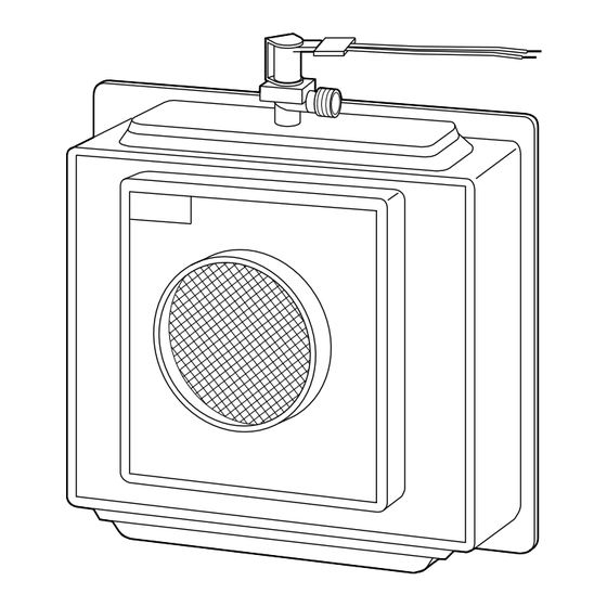
- Page 3 Do not insert tubing inside of drain fitting outlet. FAN POWERED HUMIDIFIER Bryant’s HUMBBLFP1025-A-- fan powered humidifier can only be installed on the supply plenum of a forced-air system. This unit 3. Make sure line is free of traps due to sagging and has requires an external 115-vac (fused) plug-in receptacle near the sufficient pitch to drain.
- Page 4 HUMIDIFIER HUMIDISTAT 24VAC FURNACE "N" COIL BLUE 115V FIELD WIRING FAN TYPE UNITS ONLY TRANSFORMER (FIELD SUPPLIED) HUMIDIFIER HUMIDISTAT 115V FIELD WIRING 115V FIELD WIRING VERTICAL HORIZONTAL FAN TYPE UNITS ONLY A98366 A96010 Fig. 5—Installation of HUMBBLFP1025-A-- Fig. 6—Installation of Humidistat Fan-Type Humidifier on Fan-Type Humidifier 2.
-
Page 5: Fan Powered Humidifier
3. Rotate lower mounting base 180 degrees, so side access FAN POWERED HUMIDIFIER door is now on left. Bryant’s HUMBBSFP1016-A-- fan powered humidifier can only 4. Snap together top assembly to mounting base and reinstall be installed on the supply plenum of a forced-air system. This unit screws. - Page 6 SOLENOID TUBING VALVE ENCLOSURE INLET HOLE INLET HOLE SEAT HOUSING SOLENOID ENCLOSURE VALVE FLUSH AGAINST INLET POSITION TUBING INSIDE INLET HOLE (CUT LENGTH IF REQUIRED) A97107 Fig. 10—Top Mounting of Water Solenoid Valve IV. MOUNT THE HUMIDIFIER 1. Attach foam tape to back of mounting flange (exclude the off-set edge).
-
Page 7: Bypass Humidifier
INSTALLATION OF HUMBBSBP2017-A-- BYPASS UNITS BYPASS HUMIDIFIER Bryant’s HUMBBSBP2017-A-- bypass humidifier can be installed on either the supply or return plenum of a forced air system. This unit requires an external bypass duct between the supply- and "N" COIL return-air ductwork. - Page 8 2. Use worm clamp to hold drain tubing in position over drain BYPASS WATER SAVER HUMIDIFIER fitting outlet. Bryant’s HUMBBWTR2019-A-- bypass water saver humidifier can be installed on either the supply or return plenum of a CAUTION: Unit may leak if drain tubing is misapplied.
- Page 9 II. SELECT LOCATION (SEE FIG. 14.) 8. Re-install media assembly. Ensure that square shaft of media assembly is located inside mating opening of motor BYPASS UNITS coupling. Ensure that bearing washer is located on interior side of bearing retainer. (See Fig. 15.) V.
-
Page 10: Final Steps
GASKET FLOAT RETAINER BEARING VALVE BODY ⁄ IN. LONG SCREW VALVE SEAT WASHER ⁄ IN. BLUNT SUPPORT POINT SCREW BRACKET (LEFT HAND INSTALLATION SHOWN) FLOAT VALVE ASSEMBLY REINSTALLING MEDIA ASSEMBLY A98370 Fig. 15—Valve and Media Assembly for HUMBBWTR2019-A-- VIII. INSTALL HUMIDISTAT AND COMPLETE WIRING b. - Page 11 2. Remove protective backing from template furnished with MOUNTING HOLES each control and apply self-adhesive side on return air duct at selected location. Following instructions on template and in Fig. 21, drill 2 mounting holes and six 1/4-in. diameter sensing holes in duct. Sensing holes allow return air to reach nylon sensing element and operate humidistat.
-
Page 12: Alternate Procedure
Place system in operation and observe at least 1 complete cycle to +30°F 40% (MED) make certain that all components are functioning properly. © 1998 Bryant Heating & Cooling Systems 7310 W. Morris St. Indianapolis, IN 46231 —12— Printed in U.S.A. iihum561...
Need help?
Do you have a question about the HUM and is the answer not in the manual?
Questions and answers