Table of Contents
Advertisement
Advertisement
Table of Contents

Subscribe to Our Youtube Channel
Related Manuals for BSS Audio FDS 310

Summary of Contents for BSS Audio FDS 310
- Page 1 FDS 310 User Manual...
- Page 2 V 2.0 9 August 1996 This equipment has been tested and found to comply with the following European Standards for Electromagnetic Compatibility: Emission Specification: EN55013 (1990) (Associated equipment) Immunity Specification: EN50082/1 (1992) (RF Immunity, Fast Transients and ESD) Mains Disturbance: EN61000/3/2 (1995) For continued compliance ensure that all input and output cables are wired with cable screen connected to Pin...
-
Page 3: Table Of Contents
Contents Contents What is a Crossover? The difference between Active and Passive Crossovers Other advantages The Linkwitz-Riley advantage What is special about BSS Crossovers? Unpacking Mechanical Installation Mains Power Connection Input Connections Using Jack Plugs. Using XLR Plugs. 10.0 Output Connections 10.1 Using Phone Plugs 10.2... - Page 4 Contents 16.0 LED indicators 16.1 'Signal Present' 16.2 'Peak' 17.0 Crossover Alignment Procedure: Setting the level controls 18.0 Using the Mute switch 19.0 Polarity switching and Output Polarity reversal option 20.0 Troubleshooting 21.0 Grounding/Earthing Procedures (Curing hums) 22.0 Service Section 22.1 2-Channel Sub-Woofer Operation 22.2...
-
Page 5: What Is A Crossover
Crossovers What is a Crossover? Crossovers are a necessary part of sound reinforcement systems because the loudspeaker drive-unit which can produce clear reliable high SPL (sound levels) over the full audio bandwidth has yet to be invented. All real-world drive units work best when they are driven over a limited band of frequencies, for example: Low, Mid and High. -
Page 6: The Difference Between Active And Passive Crossovers
Active and Passive Crossovers The difference between Active and Passive Crossovers Passive crossovers divide the frequency spectrum after the signal has been raised to a high power level. They are generally heavy, bulky and inefficient. Active crossovers utilise ICs and transistors, and divide the frequency spectrum at line levels immediately ahead of the amplifiers (See Figure 2.1). -
Page 7: Other Advantages
Crossover advantages Other advantages The drive-units in sound reinforcement systems utilising active crossovers benefit because: • Steep rolloffs are readily attainable. The -24dB/OCT rolloff in the BSS FDS- 310 active crossover rapidly discharges out-of-band energy. At one octave below the crossover point, power received by the driver has dropped to less than ½% (or 1/200th) of full power. -
Page 8: The Linkwitz-Riley Advantage
Linkwitz-Riley Alignment The Linkwitz-Riley advantage There is an additional set of advantages exclusive to active crossovers made by BSS, and other manufactures using the Linkwitz-Riley alignment (See Figure 4.1). Fig 4.1 Linkwitz-Riley filters Zero Phase difference at crossover: The phase difference between drivers operating in adjacent frequency bands is close to zero degrees at the crossover frequency. -
Page 9: What Is Special About Bss Crossovers
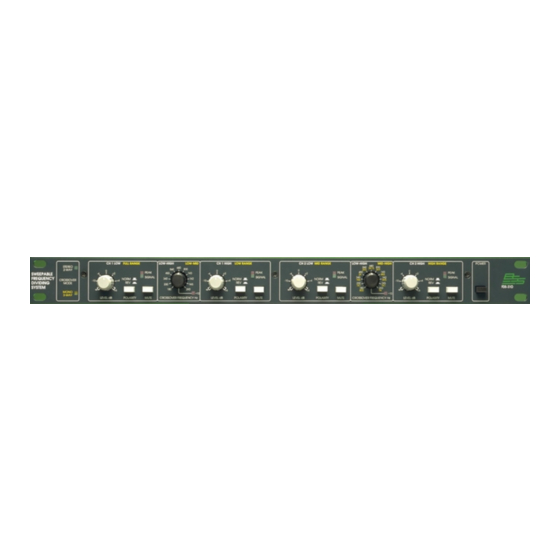
BSS Crossovers Unpacking What is special about BSS Crossovers? The FDS-310 is a condensation of over ten years experience, manufacturing the industry's most advanced active crossovers for worldwide use. The FDS- 310 contains all the features required for todays sound reinforcement systems in a compact enclosure: •... - Page 10 Getting to know the FDS-310 Fig 6.1 Front Panel Fig 6.2 Rear Panel...
- Page 11 All numbers in bubbles refer to Section numbers.
-
Page 12: Mechanical Installation
Installation Mechanical Installation A vertical rack space of 1U (1¾" / 44.5 mm high) is required. Ventilation gaps are unnecessary (See Figure 7.1). If the FDS-310 is likely to undergo extreme vibration through extensive road trucking and touring, it is advisable to support the unit at the rear and/or sides to lessen the stress on the front mounting flange. -
Page 13: Mains Power Connection
Connecting to Power Mains Power Connection Voltage: The FDS-310 operates on either 115 or 230 volt supplies. Use the voltage selector switch to choose the required voltage setting. (See Figure 8.1). Frequency: Both 60Hz and 50Hz are acceptable. Fig 8.1 Mains fuse/ Voltage selector on rear panel. -
Page 14: Input Connections
Input Connections Input Connections 9.1 Using Jack Each jack socket accepts signal sources from a 3-pole (stereo), or 2-pole (mono), 'A' gauge phone plug (See Figure 9.1). Plugs. The balanced input of the FDS-310 will accept both balanced or unbalanced signal feeds, without needing any modification. -
Page 15: Output Connections
Output Connections 10.0 Output Connections Each jack socket outputs a balanced signal - symmetrical to ground and 10.1 Using Phone floating. The output is immune from short circuits and drives low impedances Plugs and long cable runs. Each socket accepts either 2-pole or 3-pole (stereo) ¼" 'A' gauge phone plugs. -
Page 16: Connection And Setup
Setting up - 2-Way 2 Channel Operation 11.0 Connection and Setup 11.1 Selecting '2- In a 2-way system, the incoming full range signal is split into 2 bands. Normally the corresponding loudspeaker drive units cover Bass (LOW), Top Way' 2 Channel (HIGH) frequencies, and the crossover point between them lies between Operation 180Hz and 2000Hz (2kHz). -
Page 17: Selecting '3-Way' Mono Operation
Setting up - 3-Way Mono Operation 11.2 Selecting '3- In a 3-way system, the incoming full range signal is split into 3 bands. Normally the corresponding loudspeaker drive units cover Bass (LOW), Mid Way' Mono and Top (HIGH) frequencies. In this mode, the FDS-310 operates in mono and Operation there are two crossover points. -
Page 18: 2-Channel Sub-Woofer Operation
Setting up - Schematics Fig 11.1 2- and 3-Way Setups The FDS-310 can drive sub-woofers ('Sub-Low or 'Sub-Bass' cabinets) when 11.3 2-Channel switched to the 2-way configuration. The Sub-woofer-to-HIGH crossover point Sub-Woofer can lie anywhere between 18Hz and 200Hz. The 'high' output is substantially Operation a full range signal, and is normally split further into 2 or 3 bands, using a second active crossover. -
Page 19: Unusual Crossover Points - For 3-Way Systems Only
Setting up - 2-Channel Sub-Woofer Operation 12.0 Monaural Sub-Woofer Operation - for stereo 2-way systems only Because human hearing is insensitive to the location of low-frequency sound sources below 100Hz, stereo operation is normally dispensed with when driving sub-woofers. The FDS-310 contains an internal link which can be set to sum (mix) the incoming two channel (stereo) signals, so that the two sub- low outputs are identical. -
Page 20: How To Equalise Cd Horns
Equalising CD Horns 14.0 How to Equalise CD Horns Todays 'Constant Directivity' (CD) horns and drivers can be used in 2-way systems with comparatively low crossover frequencies. Even so, the laws of physics dictate that the very high efficiency attained cannot be kept up all the way to 20kHz. -
Page 21: Full Range Output - 3-Way Operation Only
Full Range Output LED Indicators 15.0 Full range Output - 3-way operation only When switched on 'MONO 3-WAY' mode, the Channel 2 input ('FULL RANGE' in 3-way mode) is not wasted. Instead, it can be used as a balanced in-out line driver passing through to the adjacent 'FULL RANGE' output sockets. -
Page 22: Crossover Alignment Procedure: Setting The Level Controls
Crossover Alignment Procedure 17.0 Crossover Alignment Procedure: Setting the level controls The modern idea is to set the crossovers' level controls so the entire speaker system exhibits a uniform, flat response, independent of the rooms' own acoustic anomalies. This means that powerful T.D.S. (Time-Delay Spectrometry) equipment is needed to make speedy, reliable measurements. - Page 23 If the mid output is not enough, even when the crossovers MID RANGE control is set at maximum (+6dB), check the mid-range power amplifiers sensitivity. If this cannot be altered, set the MID RANGE control at 0dB, then decrease the LOW RANGE control, until the two frequency bands fuse together to give an essentially straight line on the R.T.A display.
-
Page 24: Using The Mute Switch
MUTE switch • All EQ controls throughout the sound system should be set flat before setting up the FDS-310 LEVEL controls. Any house EQ adjustments can be made later. • For a 3-way set up, set the MID RANGE control first for a comfortable level. Then bring up the LOW RANGE control until the music/vocals/speech is 'filled-out'. -
Page 25: Polarity Switching And Output Polarity Reversal Option
POLARITY switch 19.0 Polarity switching and Output Polarity reversal option Each frequency bands' control surface includes a POLARITY switch (See Figure 6.1). Depressing it reverses the polarity ('phasing') of the signal emerging from the related output socket. It is a valuable 'instant' troubleshooting aid in complex multi-driver installations. -
Page 26: Troubleshooting
Troubleshooting 20.0 Troubleshooting Problem: No Output Solution: Is the MUTE switch depressed? Is the mains power on? (See section 8). Check the connections. See Fuse failure (below). Do you have an input signal? Is the SIGNAL LED on? Check the input and output connections (See sections 9 & 10). Are the power amplifiers switched on? Problem: High Frequency signal from 'LOW' output... -
Page 27: Grounding/Earthing Procedures (Curing Hums)
Grounding/Earthing 21.0 Grounding/Earthing Procedures (Curing hums) The FDS-310 is supplied with the signal ground (0V) tied to chassis, which is connected in turn to: • Mains ground (earth). • Other equipment chassis' in the rack. If the FDS-310 outputs are connected to amplifiers with unbalanced inputs, it will normally be necessary to disconnect the internal ground link, to prevent ground-loop hums. -
Page 28: Service Section
!!! WARNING - Refer all servicing to qualified service personnel !!! Risk of electric shock if the unit is opened. BSS Audio accepts no responsibility for injury subsequent to opening of the unit. -
Page 29: Activating Equalisation
Fig 22.3 Locating the CD HORN EQ switches !!! WARNING - Refer all servicing to qualified service personnel !!! Risk of electric shock if the unit is opened. BSS Audio accepts no responsibility for injury subsequent to opening of the unit. -
Page 30: Eliminating Hum
!!! WARNING - Refer all servicing to qualified service personnel !!! Risk of electric shock if the unit is opened. BSS Audio accepts no responsibility for injury subsequent to opening of the unit. -
Page 31: Glossary
Glossary 23.0 Glossary Active Active electronic circuits are those which are capable of voltage and power gain by using transistors and integrated circuits. Amplitude Refers to the voltage level or intensity of a signal, and is usually measured in voltage or decibels. Balanced A three wire connection in which two of the wires carry the signal information, and the third acts as a shield tied to chassis ground. - Page 32 Glossary Equalisation Modification of the frequency response of an audio system, regardless of level, for corrective or enhancement purposes. Frequency The repetition of a waveform. The unit of frequency is Hz, and 1 cycle per second is equal to 1Hz. The audio band is generally restricted to frequencies of 20Hz to 20,000Hz (20kHz).
-
Page 33: Specifications
Specifications 24.0 Specifications Input Impedance: Balanced bridging; 12k ohms Max. Input Level: +20dBm/dBu/dBv Through Gain: Input to any output with level control set at 0dB: 0dB Fully adjustable from - to +6dB. Input CMRR: (Common Mode Rejection Ratio) <-50dB at 120Hz <-50dB at 10kHz Max. -
Page 34: Warranty Information
25.0 Warranty Information This unit is warranted by BSS Audio to the original end user purchaser against defects in workmanship and the materials used in its manufacture for a period of one year from the date of shipment to the end user. -
Page 35: Index
Index Symbols Index 2-Channel Sub-Woofer LED indicators Operation. See Setting up 2-Way 2 Channel Operation. See Setting up Mains Connection 3-Way Mono Operation. See Setting Monaural Sub-Woofer Operation 20 Mute switch Active Crossovers Output Connections Output Polarity Reversal Balanced Input. See Input Connec- tions Passive Crossovers. - Page 36 Index Warranty Info. Wiring Convention. See Input Connections: Output Connec- tions XLR Plugs. See Input Connections Zero Phase difference. See Linkwitz- Riley filters...
-
Page 37: User Notes
User Notes... - Page 38 User Notes...
- Page 39 User Notes...
- Page 40 User Notes...
Need help?
Do you have a question about the FDS 310 and is the answer not in the manual?
Questions and answers