Advertisement
Quick Links
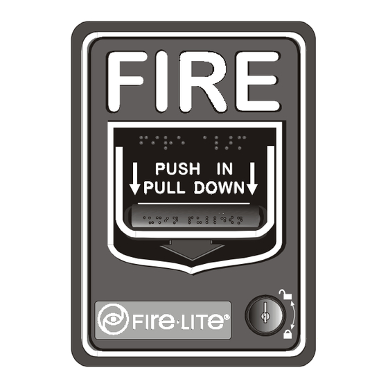
BG-12LX Addressable Pull Station
Document 51094
Revision A2
Description
The BG-12LX Addressable pull station is a non-coded,
dual-action manual pull station with a key-lock reset fea-
ture. It provides Fire•Lite intelligent control panels with
one addressable alarm initiating input. The addressable
module is housed inside the pull station. The BG-12LX
is compatible with all Fire•Lite intelligent panels. The
BG-12LX meets the ADA requirement for a 5-lb. maxi-
mum pull force to activate the pull station. Operating
instructions are molded into the pull station handle along
with Braille text. Molded Terminal numbers are also
present.
Installation
The BG-12LX Addressable pull station can be surface
mounted to an SB-10 surface backbox or semi-flush
mounted on a standard single-gang, double-gang or 4"
(10.16 cm) square electrical box. The optional BG-TR
trim ring can be used if the BG-12LX is to be semi-flush
mounted.
Ratings
Normal Operating Voltage: 24 VDC.
Average Operating Current (LED Flash): 300 µA.
Temperature Range: 32 o F - 120 o F (0 o C - 49 o C).
Relative Humidity Range: 10% - 93% non-condensing.
ECN 00-032
01/14/2000
Setting the BG-12LX Address
The BG-12LX Addressable pull station is factory preset
with address '00.' Set the address for the pull station by
turning the rotary address switches on the addressable mod-
ule mounted inside the pull station. Only one device per
address is allowed. Multiple modules may not be set to
the same address on the Signaling Line Circuit. Once the
address is set, record it in the space provided on the prod-
uct ID label located inside the pull station.
ROTARY ADDRESS SWITCHES
LED OPERATION
Normal:
Flash RED
Alarm:
Steady RED
Note: LED is visible
through translucent
handle.
If, during mounting of the pull station, the door be-
comes detached, complete the following steps to reattach
the door to the backplate. The door cannot be connected
to the pull station if the unit is mounted to the backbox.
1. Position the door and backplate side by side in the
full open position. (i.e. 180-degrees with respect to
each other.)
2. With the backplate position fixed, move the door be-
hind the backplate, as shown in the illustration, part
A.
3. Align the hinge posts and holes by bringing the door
up to meet the backplate, paying particular attention
to the 'keying' that occurs when the door's post hole
is aligned to the backplate's hinge post. Refer to the
illustration, part B.
4. With the two pieces aligned and 'keyed' together, slide
the holes down onto the posts. Refer to the illustra-
tion, part C.
5. Holding the backplate, close the door and backplate
slightly to lock the door and backplate together.
LED
0
1 5
0
1
1
1 4
2
1 3
2
1 2
3
3
4
3
2
1
11
4
4
1 0
5
5
9
6
9
6
8
7
8
7
O NE S
T ENS
M
L U
NOTIFIER
NBG - 12 Series
PRO DU CT IDEN TIFIC ATIO N LAB EL
REFER TO D OC UMEN T
Advertisement

Related Manuals for Fire-Lite BG-12LX


Summary of Contents for Fire-Lite BG-12LX
- Page 1 Setting the BG-12LX Address The BG-12LX Addressable pull station is factory preset with address ‘00.’ Set the address for the pull station by turning the rotary address switches on the addressable mod- ule mounted inside the pull station. Only one device per address is allowed.
- Page 2 Operation Push-in and pull-down the handle where indicated to activate the station. The BG-12LX manual fire alarm pull station includes one SPST (Single Pole, Single Throw) N/O (normally-open) switch and the addressable mod- ule located inside the station. Pushing-in and pulling-down the dual action handle causes the N/O alarm switch to close.
Need help?
Do you have a question about the BG-12LX and is the answer not in the manual?
Questions and answers