Table of Contents
Advertisement
Advertisement
Table of Contents

Subscribe to Our Youtube Channel
Related Manuals for Electrolux ER 6633 I

Summary of Contents for Electrolux ER 6633 I
- Page 1 I N F O I N S T R U C T I O N B O O K L E T REFRIGERATOR ER 6633 I 2222747-46...
-
Page 2: Table Of Contents
CONTENTS Instructions for the User Important Safety Instructions Description of the Appliance Operation Before use Setting the temperature Fresh food refrigeration The door shelves Health and safety guidelines Defrosting Normal Operating Sounds Maintenance and Cleaning Internal cleaning Changing the light bulb When the appliance is not in use Something not Working? Service and Spare Parts... -
Page 3: Important Safety Instructions
Do not store any containers with flammable materials, such as spray cans, fire extinguisher refill cartridges etc. in the refrigerator. Maintenance and Cleaning Before cleaning, always switch off the appliance and disconnect from the electrical supply. -
Page 4: Description Of The Appliance
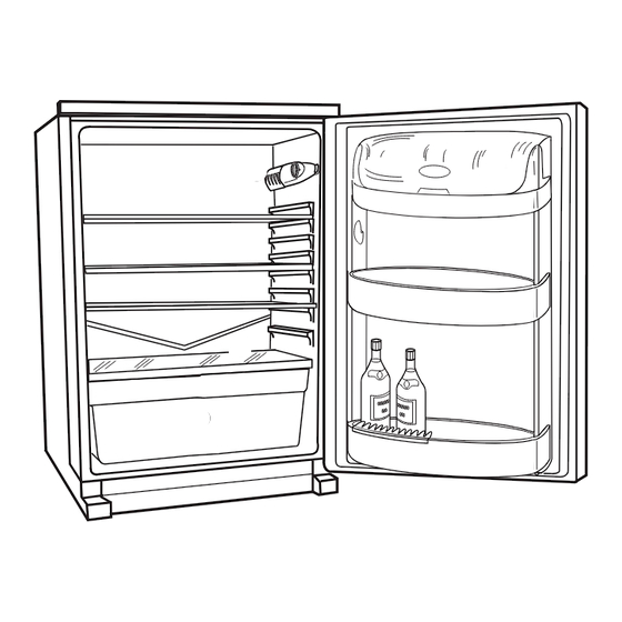
DESCRIPTION OF THE APPLIANCE Dairy compartment Can storage shelf Bottle storage shelf Salad bin Glass shelf (for storing fresh meat) Storage shelves Thermostat control... -
Page 5: Operation
Do not cover the shelves with any protective material, such as paper, cardboard or plastic, which may obstruct the air circulation through them. To help you use your refrigerator correctly, here are some more useful hints: Raw meat (beef, pork, lamb & poultry): wrap in polythene bags and place on top of the salad drawer. -
Page 6: Health And Safety Guidelines
22°C in an hour between the supermarket and home. It then took 11 hours to get down to 7°C in the refrigerator. Keep the refrigerator door closed as much as possible. Do not push food together too much, try to allow air to circulate around each item. -
Page 7: Defrosting
To avoid defrost water overflowing into the fridge, periodically clean the water discharge hole in the centre of the V shaped drip collector at the back of the refrigerator compartment behind the fruit and salad drawers. Use the special cleaner provided which you will find already inserted into the discharge hole. -
Page 8: Maintenance And Cleaning
Unscrew the bulb and replace it with a new 15 watt bulb (available from your nearest Electrolux Service Centre). Replace the light cover by sliding it into its original position and replacing the screw. -
Page 9: Something Not Working
SOMETHING NOT WORKING? Before contacting your local Service Force Centre check the following points. Symptom No power to appliance The light does not come on The temperature in the fridge is too high The compressor runs continuously Excessive frost and ice has built up Noise Water under the salad bin If after the above checks, there is still a fault, call your local Service Force Centre. -
Page 10: Service And Spare Parts
SERVICE AND SPARE PARTS In the event of your appliance requiring service, or if you wish to purchase spare parts please contact your local Electrolux Service Force Centre by telephoning: 08705 929929 Your telephone call will be automatically routed to the Service Centre covering your post code area. -
Page 11: Guarantee Conditions
Standard guarantee conditions We, Electrolux, undertake that if within 12 months of the date of purchase this Electrolux appliance or any part thereof is proved to be defective by reason only of faulty workmanship or materials, we will, at our option repair or replace the same FREE OF CHARGE for labour, materials or carriage on condition that: The appliance has been correctly installed and used only on the electricity supply stated on the rating plate. -
Page 14: Technical Specifications
TECHNICAL SPECIFICATIONS POWER SUPPLY VOLTAGE AND FREQUENCY TOTAL POWER ABSORBED AVERAGE DAILY UNITS ELECTRICITY(*) GROSS CAPACITY NET CAPACITY (*)This figure is based on standard test results in accordance with European Standard EN153. Actual consumption will depend on how the appliance is used and where it is located. INSTALLATION Positioning The appliance should be installed well away from... -
Page 15: Electrical Connection
The cover/carrier is indicated by the coloured insert at the base of the plug. A replacement cover/carrier must be obtained from your local Electrolux Service Force Centre. This appliance complies with the E.E.C. Directive No. 87/308 of 2.6.87 relative to radio interference suppression. -
Page 16: Building In
BUILDING IN Instructions for building in the appliance Dimensions of the recess Height of housing 880 mm Depth of housing 550 mm Width of housing 560 mm For appropriate venting, follow indications in the figure. Push the appliance into the housing until the stop strip (A) touches the kitchen unit. - Page 17 Press in the joint covers between the appliance and the kitchen furniture. Apply covers (B) on joint cover lugs and hinge holes. Position the runners (H) at the top and bottom of the inside of the kitchen unit as shown in the figure and mark the position of the external holes.
- Page 20 © Electrolux Household Appliances Limited 2000...
Need help?
Do you have a question about the ER 6633 I and is the answer not in the manual?
Questions and answers